Firearm Sound Suppressor
Griffis; Travis
U.S. patent application number 16/017878 was filed with the patent office on 2019-01-17 for firearm sound suppressor. The applicant listed for this patent is Travis Griffis. Invention is credited to Travis Griffis.
| Application Number | 20190017767 16/017878 |
| Document ID | / |
| Family ID | 65000159 |
| Filed Date | 2019-01-17 |


| United States Patent Application | 20190017767 |
| Kind Code | A1 |
| Griffis; Travis | January 17, 2019 |
FIREARM SOUND SUPPRESSOR
Abstract
Implementations of a firearm sound suppressor are provided. The firearm sound suppressor comprises a non-cylindrical, monolithic baffle core that is enclosed by a front plate and a back plate. In some implementations, the baffle core may comprise a proximal end configured to mount onto the muzzle of a firearm barrel, a distal end having an outlet aperture, and a plurality of baffles. The plurality of baffles may be positioned transverse to a projectile pathway extending through the sound suppressor and form expansion chambers therebetween. In this way, propellant gasses generated by the discharge of a firearm may be dispersed throughout the interior of the sound suppressor, and directed away from the projectile pathway extending therethrough, by the shearing effect of each baffle. The baffle core may further comprise two longitudinally extending expansion chambers, each of which may be in fluid communication with ports extending through an exterior sidewall of the baffle core.
| Inventors: | Griffis; Travis; (Brunswick, GA) | ||||||||||
| Applicant: |
|
||||||||||
|---|---|---|---|---|---|---|---|---|---|---|---|
| Family ID: | 65000159 | ||||||||||
| Appl. No.: | 16/017878 | ||||||||||
| Filed: | June 25, 2018 |
Related U.S. Patent Documents
| Application Number | Filing Date | Patent Number | ||
|---|---|---|---|---|
| 62524995 | Jun 26, 2017 | |||
| Current U.S. Class: | 1/1 |
| Current CPC Class: | F41A 21/30 20130101 |
| International Class: | F41A 21/30 20060101 F41A021/30 |
Claims
1. A sound suppressor for a firearm comprising: a baffle core, the baffle core comprises a proximal end having an inlet aperture, a distal end having an outlet aperture, and at least one baffle positioned between the proximal end and the distal end to define a plurality of expansion chambers, the baffle core defines a longitudinally extending projectile pathway that extends from the inlet aperture to the outlet aperture; wherein the at least one baffle is positioned transverse to the projectile pathway; wherein the at least one baffle comprises a ridge feature having a first curved member and a second curved member extending from opposite sides thereof, one end of the first curved member is connected to a first interior sidewall of the baffle core, and one end of the second curved member is connected to a second interior sidewall of the baffle core; wherein the at least one baffle includes an aperture that extends through the ridge feature thereof, the aperture is coaxial with the longitudinally extending projectile pathway; a front plate configured to cover a first side of the baffle core; and a back plate configured to cover a second side of the baffle core.
2. The sound suppressor of claim 1, wherein the baffle core further comprises a first longitudinally extending expansion chamber and a second longitudinally extending expansion chamber, both longitudinally extending expansion chambers are in fluid communication with an expansion chamber defined by the at least one baffle positioned transverse to the longitudinally extending projectile pathway of the baffle core.
3. The sound suppressor of claim 2, wherein the first longitudinally extending expansion chamber is in fluid communication with at least one port extending through a first exterior sidewall of the baffle core; and wherein the second longitudinally extending expansion chamber is in fluid communication with at least one port extending through a second exterior sidewall of the baffle core.
4. The sound suppressor of claim 3, wherein the first longitudinally extending expansion is positioned between the first interior sidewall and the first exterior sidewall of the baffle core; and wherein the second longitudinally extending expansion chamber is positioned between the second interior sidewall and the second exterior sidewall of the baffle core.
5. The sound suppressor of claim 1, wherein the ridge feature of the at least one baffle includes an apex, the apex points towards the proximal end of the baffle core.
6. The sound suppressor of claim 1, wherein the front plate and the back plate are removably secured to the baffle core.
7. The sound suppressor of claim 6, wherein the front plate is secured to the first side of the baffle core by a plurality of threaded fasteners and the back plate is secured to the second side of the baffle core by a plurality of threaded fasteners.
8. A sound suppressor for a firearm comprising: a baffle core, the baffle core comprises a proximal end having an inlet aperture, a distal end having an outlet aperture, a longitudinally extending rib feature, and at least one baffle positioned between the proximal end and the distal end to define a plurality of expansion chambers, the baffle core defines a longitudinally extending projectile pathway that extends from the inlet aperture to the outlet aperture; wherein the at least one baffle is positioned transverse to the projectile pathway; wherein the at least one baffle comprises a first curved member and a second curved member that extend from opposite sides of the longitudinally extending rib feature, one end of the first curved member is connected to a first interior sidewall of the baffle core, and one end of the second curved member is connected to a second interior sidewall of the baffle core; wherein the longitudinally extending rib feature includes an aperture that extends therethrough, the aperture is coaxial with the longitudinally extending projectile pathway; a front plate configured to cover a first side of the baffle core; and a back plate configured to cover a second side of the baffle core.
9. The sound suppressor of claim 8, wherein the baffle core further comprises a first longitudinally extending expansion chamber and a second longitudinally extending expansion chamber, each longitudinally extending expansion chambers is in fluid communication with an expansion chamber defined by the at least one baffle positioned transverse to the longitudinally extending projectile pathway of the baffle core.
10. The sound suppressor of claim 9, wherein the first longitudinally extending expansion chamber is in fluid communication with at least one port extending through a first exterior sidewall of the baffle core; and wherein the second longitudinally extending expansion chamber is in fluid communication with at least one port extending through a second exterior sidewall of the baffle core.
11. The sound suppressor of claim 10, wherein the first longitudinally extending expansion is positioned between the first interior sidewall and the first exterior sidewall of the baffle core; and wherein the second longitudinally extending expansion chamber is positioned between the second interior sidewall and the second exterior sidewall of the baffle core.
12. The sound suppressor of claim 8, wherein the front plate and the back plate are removably secured to the baffle core.
13. The sound suppressor of claim 12, wherein the front plate is secured to the first side of the baffle core by a plurality of threaded fasteners and the back plate is secured to the second side of the baffle core by a plurality of threaded fasteners.
Description
CROSS REFERENCE TO RELATED APPLICATION
[0001] This application claims the benefit of U.S. Provisional Application Ser. No. 62/524,995, which was filed on Jun. 26, 2017, and is incorporated herein by reference in its entirety.
TECHNICAL FIELD
[0002] This disclosure relates to implementations of a firearm sound suppressor.
BACKGROUND
[0003] A firearm sound suppressor, or silencer, is a device that reduces the noise and muzzle flash emitted by a firearm when it's discharged. A sound suppressor may be a detachable accessory to, or an integral part of, a firearm's barrel. In general, a sound suppressor reduces noise and muzzle flash by allowing the propellent gasses resulting from the discharge of a firearm to be decelerated and cooled prior to exiting.
[0004] A typical sound suppressor design comprises a cylindrical metal tube having internal baffles that are configured to delay the flow, expansion, and exiting of the propellent gasses from interior expansion chambers. The result is a reduction in the noise and muzzle flash produced by the exiting propellant gases.
[0005] The propellent gasses produced during the discharge of a firearm are dispersed within the silencer. At the same time, lead and carbon deposits are also dispersed within the silencer, and after repeated firings, result in a build-up therein. To remove these built-up deposits from the sound suppressor, the sound suppressor needs to be disassembled for cleaning. In preparation for this cleaning, it is important that the baffles be easily accessible for maintenance.
[0006] Accordingly, it can be seen that needs exist for the firearm sound suppressor disclosed herein. It is to the provision of a firearm sound suppressor configured to address these needs, and others, that the present invention in primarily directed.
SUMMARY OF THE INVENTION
[0007] Implementations of a sound suppressor, or silencer, for a firearm are provided. The firearm sound suppressor is configured to permit a fired projectile (i.e., a bullet) to freely pass through the sound suppressor along a longitudinal axis thereof, while dispersing the resulting flow of high-pressure gases throughout the sound suppressor. In this way, the impulse noise and the muzzle flash generated by the discharge of the firearm may be mitigated by the firearm sound suppressor. In some implementations, the firearm sound suppressor is configured to be disassembled for service (e.g., cleaning and/or repair).
[0008] In some implementations, the firearm sound suppressor comprises a monolithic baffle core having a front plate and a back plate secured thereto.
[0009] In some implementations, the baffle core may comprise a proximal end configured to mount onto the muzzle of a firearm barrel, a distal end having an outlet aperture, and a plurality of baffles (e.g., six, but there could be more than, or less than, six baffles). The baffles of the baffle core are positioned to form expansion chambers therebetween. In some implementations, the baffle core may further comprise a first longitudinally extending expansion chamber and a second longitudinally extending expansion chamber that may be in fluid communication with ports extending through a first exterior sidewall and a second exterior sidewall, respectively, of the baffle core. In this way, a measured portion of any gasses trapped within the sound suppressor may be discharged through the ports.
[0010] In some implementations, the proximal end of the firearm sound suppressor may comprise a socket having an internal thread that is suitable for affixing the proximal end of the firearm sound suppressor onto a threaded muzzle of a firearm barrel.
[0011] In some implementations, the outlet aperture in the distal end of the firearm sound suppressor is configured to permit the unobstructed passage of a discharged projectile (i.e., a bullet). Also, at least a portion of any gasses trapped by, and dispersed throughout, the sound suppressor by the baffles may be discharged through the outlet aperture.
[0012] In some implementations, each baffle may be positioned transverse to a projectile pathway extending through the firearm sound suppressor. In this way, propellant gasses generated by the discharge of a firearm may be dispersed throughout the interior of the sound suppressor, and directed away from the projectile pathway extending therethrough, by the shearing effect of each baffle. In some implementations, each baffle may comprise a ridge feature having a first curved member and a second curved member extending from opposite sides thereof, one end of each curved member is connected to, and supported by, an interior sidewall of the baffle core. In some implementations, the apex of each ridge feature points towards the proximal end of the firearm sound suppressor. In some implementations, a centrally positioned aperture extends through the ridge feature of each baffle.
[0013] In another example implementation, the baffle core may further comprise a longitudinally extending rib feature. Each baffle of this baffle core may comprise a first curved member and a second curved member that extend from opposite sides of the rib feature, one end of each curved member is connected to an interior sidewall of the baffle core. In some implementations, a centrally positioned aperture may extend through the rib feature of the baffle core. This longitudinally extending aperture defines a portion of the projectile pathway that extends through the baffle core and openings that connect adjacent expansion chambers. In this way, a fired projectile is able to freely pass through the baffle core along the longitudinal axis thereof and adjacent expansion chambers separated by the rib feature are placed into fluid communication. Accordingly, the longitudinally extending aperture allows the flow of high-pressure gases resulting from the discharge of a firearm to be dispersed throughout the interior of the sound suppressor by the baffles.
[0014] In some implementations, each expansion chamber of the baffle core may be configured to contain expanding propellant gasses dispersed therein by the baffles. In this way, the expanding gases are given time to cool as there progression through the sound suppressor is delayed.
[0015] In some implementations, the first longitudinally extending expansion chamber is positioned between the first interior sidewall and the first exterior sidewall of the baffle core, and the second longitudinally extending expansion chamber is positioned between the second interior sidewall and the second exterior sidewall of the baffle core.
[0016] In some implementations, the first longitudinally extending expansion chamber and the second longitudinally extending expansion chamber of the baffle core may be in fluid communication with a first expansion chamber via a first passage and a second passage, respectively. The first passage and the second passage may each extend through a segment of the first interior sidewall and the second interior sidewall, respectively, that separates the first expansion chamber from the longitudinally extending expansion chambers. In this way, at least a portion of the expanding propellant gasses dispersed within the initial expansion chamber are able to flow through each passage, into a first end of each longitudinally extending expansion chamber, before exiting the second end thereof through the ports extending through the exterior sidewalls of the baffle core.
[0017] In some implementations, there may be no ports extending through the exterior sidewalls of the baffle core.
[0018] In some implementations, the projectile pathway of the baffle core extends from the inlet aperture of the proximal end, through the aperture in each baffle, to the outlet aperture of the distal end. In this way, when the proximal end of the firearm sound suppressor is affixed to the muzzle of a firearm barrel, a fired projectile is able to freely pass through the sound suppressor along the longitudinal axis thereof, while the resulting flow of high-pressure gases are dispersed throughout the sound suppressor by the baffles. In some implementations, the projectile pathway may be co-axially aligned with the longitudinal axis of the firearm sound suppressor.
[0019] In some implementations, the front plate and/or the back plate may be removably secured to the baffle core using a plurality of threaded fasteners. In this way, the baffle core may be serviced by the user (e.g., cleaned and/or repaired).
[0020] In some implementations, the firearm sound suppressor may be configured to removably secure to a flash hider, a muzzle brake, and/or another suitable mount positioned on the muzzle of a firearm barrel.
BRIEF DESCRIPTION OF THE DRAWINGS
[0021] FIG. 1 illustrates an isometric bottom view of an example firearm sound suppressor according to the principles of the present disclosure.
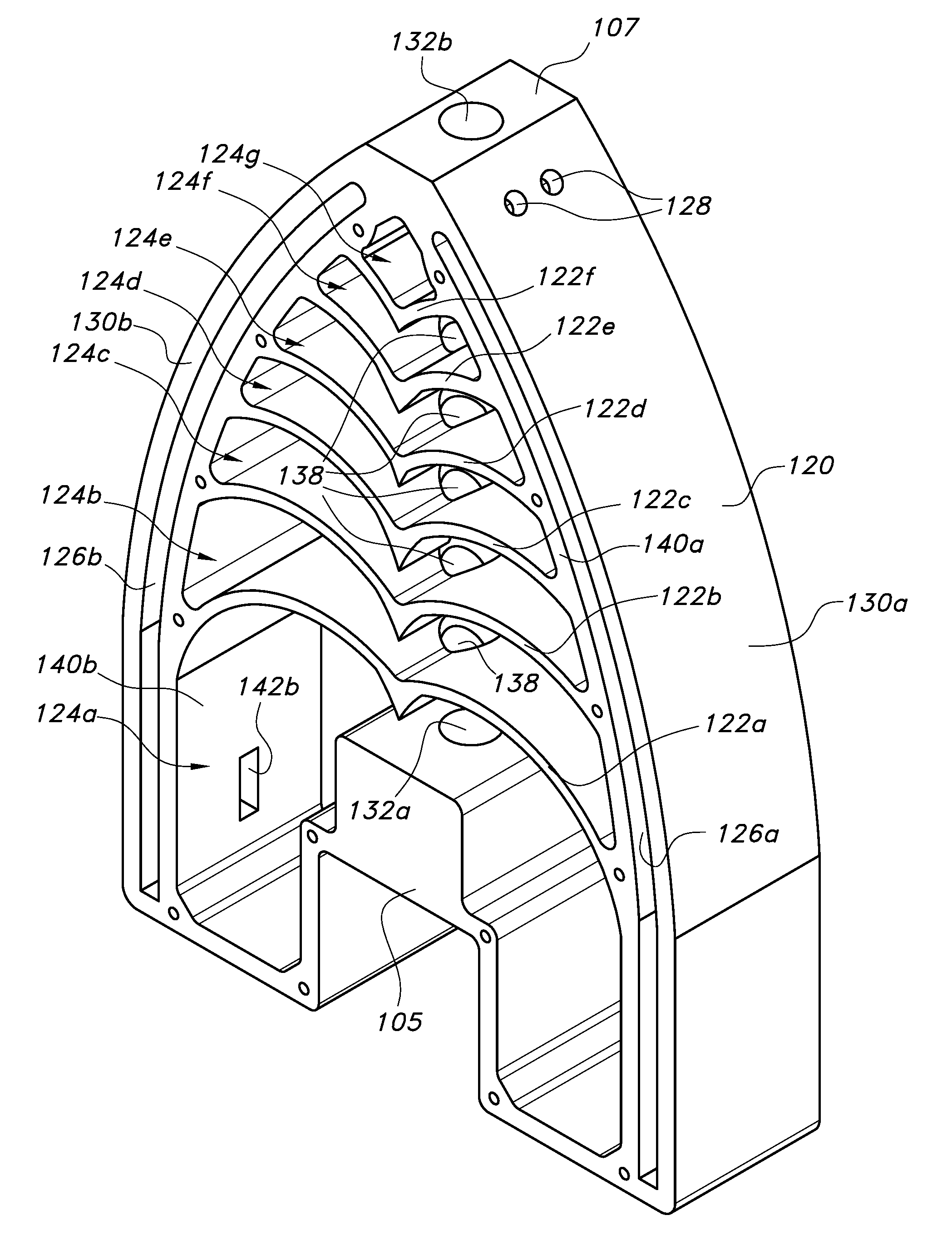
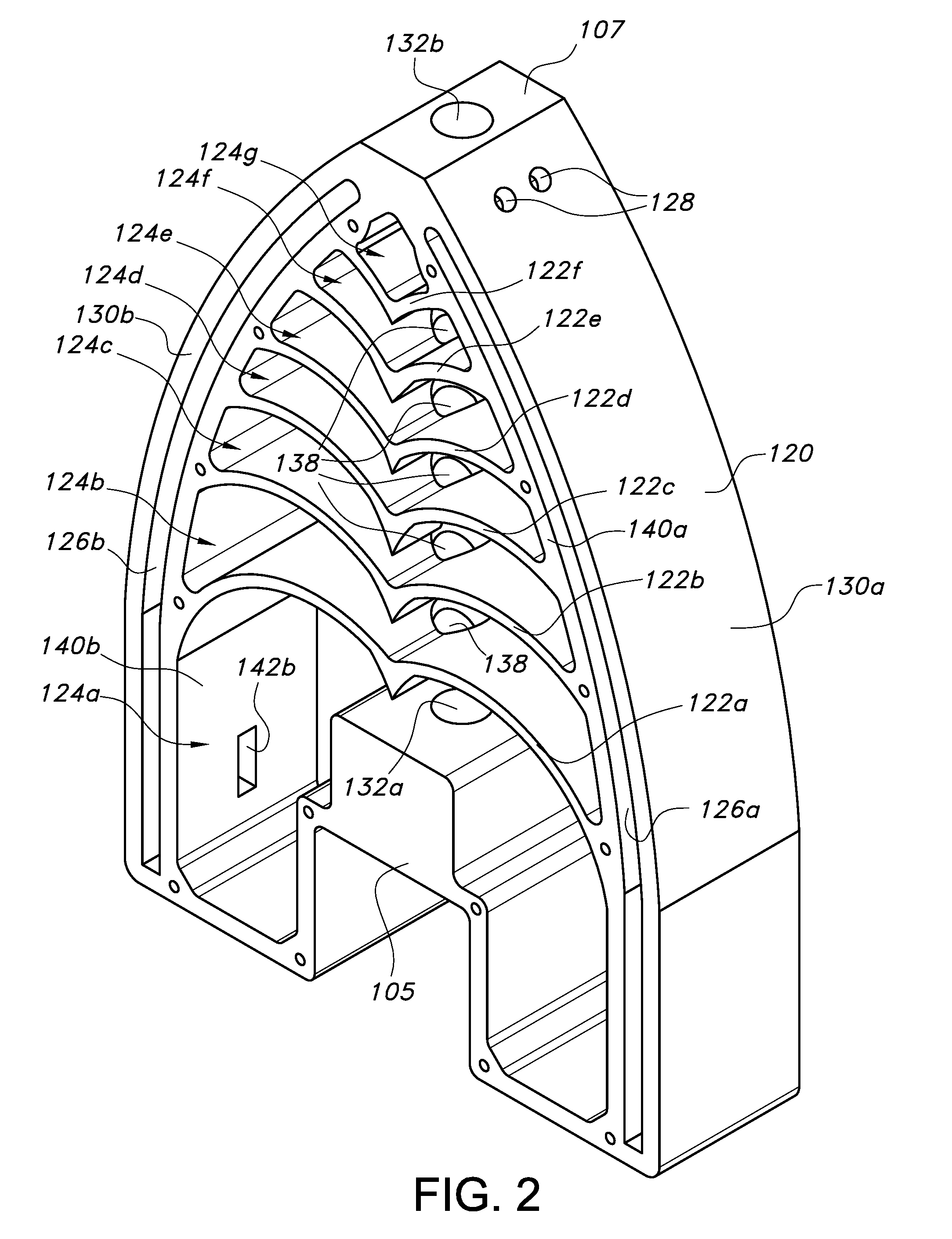
[0022] FIG. 2 illustrates an isometric top view of an example baffle core according to the principles of the present disclosure.
[0023] FIG. 3 is an exploded view of the firearm sound suppressor shown in FIG. 1.
[0024] FIG. 4 is another view of the baffle core shown in FIG. 2.
[0025] FIG. 5 illustrates an isometric top view of another example baffle core according to the principles of the present disclosure.
[0026] FIG. 6 is another view of the baffle core shown in FIG. 5.
[0027] Like reference numerals refer to corresponding parts throughout the several views of the drawings.
DETAILED DESCRIPTION
[0028] FIGS. 1-4 illustrate an example firearm sound suppressor 100, or silencer, according to the principles of the present disclosure. In some implementations, the proximal end 105 of the firearm sound suppressor 100 is configured to mount onto the muzzle of a firearm barrel. In some implementations, the firearm sound suppressor 100 may be configured to permit a fired projectile (i.e., a bullet) to freely pass through the sound suppressor 100 along a longitudinal axis 102 thereof, while dispersing the resulting flow of high-pressure gases throughout the sound suppressor 100. In this way, the impulse noise and the muzzle flash generated by the discharge of the firearm may be mitigated by the firearm sound suppressor 100. In some implementations, the firearm sound suppressor 100 may be configured to be disassembled for service (e.g., cleaning and/or repair).
[0029] As shown in FIGS. 1 and 3, in some implementations, the firearm sound suppressor 100 may comprise a monolithic baffle core 120 having a front plate 110 and a back plate 115 secured thereto.
[0030] As shown in FIGS. 2 and 4, in some implementations, the baffle core 120 may comprise a proximal end 105, a distal end 107, and a plurality of baffles 122a, 122b, 122c, 122d, 122e, 122f (collectively baffles 122). While a baffle core 120 having six baffles 122 is shown, in some implementations, the baffle core 120 may include more than six, or less than six, baffles 122. In some implementations, the baffles 122 of the baffle core 120 are positioned to form expansion chambers 124 therebetween. In some implementations, the baffle core 120 may further comprise a first longitudinally extending expansion chamber 126a and a second longitudinally extending expansion chamber 126b that may be in fluid communication with ports 128 extending through a first exterior sidewall 130a and a second exterior sidewall 130b, respectively, of the baffle core 120 (see, e.g., FIGS. 2 and 4). In this way, a measured portion of any gasses trapped within the sound suppressor 100 may be discharged through the ports 128.
[0031] As shown in FIGS. 1 and 4, in some implementations, the proximal end 105 of the firearm sound suppressor 100 may include a direct thread mount 106 therein. In some implementations, the thread mount 106 may comprise a socket having an internal thread that is suitable for affixing the proximal end 105 of the firearm sound suppressor 100 onto a threaded muzzle of a firearm barrel. In some implementations, the thread mount 106 is not a discrete piece of the baffle core 120 (see, e.g., FIG. 4). In some implementations, the thread mount 106 is a discrete piece that is secured to the baffle core 120 of the firearm sound suppressor 100.
[0032] As shown in FIG. 4, in some implementations, the proximal end 105 of the firearm sound suppressor 100 may also include an inlet aperture 132a that extends from a front end of the thread mount 106 to a first expansion chamber 124a of the baffle core 120. In some implementations, the inlet aperture 132a may be co-axially aligned with the socket of the direct thread mount 106. In this way, the inlet aperture 132a may be co-axially aligned with the bore of a firearm barrel to which the sound suppressor 100 is affixed.
[0033] As shown in FIGS. 2 and 4, in some implementations, the distal end 107 of the firearm sound suppressor 100 may include an outlet aperture 132b therein that is configured to permit the unobstructed passage of a discharged projectile (i.e., a bullet). In this way, a discharged projectile can exit the firearm sound suppressor 100 without making contact therewith. Also, at least a portion of any gasses trapped, and dispersed throughout the sound suppressor 100, by the baffles 122 may be discharged through the outlet aperture 132b.
[0034] As shown in FIGS. 2 and 4, in some implementations, each baffle 122a, 122b, 122c, 122d, 122e, 122f may be positioned transverse to a projectile pathway extending through the firearm sound suppressor 100. In this way, propellant gasses generated by the discharge of a firearm may be dispersed throughout the interior of the sound suppressor 100, and directed away from the projectile pathway extending therethrough, by the shearing effect of each baffle 122. In some implementations, each of the baffles 122 may comprise a ridge feature 134 having a first curved member 136a and a second curved member 136b extending from opposite sides thereof, one end of each curved member 136a, 136b is connected to, and supported by, an interior sidewall 140a, 140b of the baffle core 120. In some implementations, the apex of each ridge feature 134 points towards the proximal end 105 of the firearm sound suppressor 100. In some implementations, a centrally positioned aperture 138 may extend through the ridge feature of each baffle 122a, 122b, 122c, 122d, 122e, 122f (see, e.g., FIG. 4).
[0035] In some implementations, the opening defined by the inlet aperture 132a, the central aperture 138 extending through each baffle 122, and the outlet aperture 132b is larger than the caliber of the projectile to be passed therethrough.
[0036] As shown in FIG. 4, in some implementations, each expansion chamber 124a, 124b, 124c, 124d, 124e, 124f, 124g of the baffle core 120 may be configured to contain expanding propellant gasses dispersed therein by the baffles 122. In this way, the expanding gases are given time to cool as there progression through the sound suppressor 100 is delayed.
[0037] As shown in FIG. 4, in some implementations, the volume of the first expansion chamber 124a may be defined by the position of the first baffle 122a relative to the back end 103 of the baffle core 120. In some implementations, a portion of the first expansion chamber 124a may extend rearwardly past the proximal end 105 of the baffle core 120 on two sides thereof (see, e.g., FIG. 4).
[0038] In some implementations, the volume of the second expansion chamber 124b may be defined by the position of the second baffle 122b relative to the first baffle 122a of the baffle core 120 (see, e.g., FIG. 4).
[0039] In some implementations, the volume of the third expansion chamber 124c may be defined by the position of the third baffle 122c relative to the second baffle 122b of the baffle core 120 (see, e.g., FIG. 4).
[0040] In some implementations, the volume of the fourth expansion chamber 124d may be defined by the position of the fourth baffle 122d relative to the third baffle 122c of the baffle core 120 (see, e.g., FIG. 4).
[0041] In some implementations, the volume of the fifth expansion chamber 124e may be defined by the position of the fifth baffle 122e relative to the fourth baffle 122d of the baffle core 120 (see, e.g., FIG. 4).
[0042] In some implementations, the volume of the sixth expansion chamber 124f may be defined by the position of the sixth baffle 122f relative to the fifth baffle 122e of the baffle core 120 (see, e.g., FIG. 4).
[0043] In some implementations, the volume of the seventh expansion chamber 124g may be defined by the position of the outlet aperture 132b relative to the sixth baffle 122f of the baffle core 120 (see, e.g., FIG. 4).
[0044] As shown in FIG. 4, in some implementations, the first longitudinally extending expansion chamber 126a may be positioned between the first interior sidewall 140a and the first exterior sidewall 130a of the baffle core 120, and the second longitudinally extending expansion chamber 126b may be positioned between the second interior sidewall 140b and the second exterior sidewall 130b of the baffle core 120.
[0045] As shown in FIG. 4, in some implementations, the first longitudinally extending expansion chamber 126a and the second longitudinally extending expansion chamber 126b of the baffle core 120 may be in fluid communication with the first expansion chamber 124a via a first passage 142a and a second passage 142b, respectively. In some implementations, the first passage 142a and the second passage 142b may each extend through the segment of the first interior sidewall 140a and the second interior sidewall 140b, respectively, that separates the first expansion chamber 124a from the longitudinally extending expansion chambers 126a, 126b (see, e.g., FIGS. 2 and 4). In this way, at least a portion of the expanding propellant gasses dispersed within the initial expansion chamber 126a are able to flow through each passage 142a, 142b, into a first end of each longitudinally extending expansion chamber 126a, 126b, before exiting the second end thereof through the ports 128 extending through the exterior sidewalls 130 of the baffle core 120.
[0046] As shown in FIG. 4, in some implementations, there may be two ports 128 extending through the first exterior sidewall 130a and/or the second exterior sidewall 130b of the baffle core 120. In some implementations, there may be more than two, or less than two, ports 128 extending through the first exterior sidewall 130a and/or the second exterior sidewall 130b of the baffle core 120. In some implementations, there may be no ports extending through the exterior sidewalls 130a, 130b of the baffle core 120.
[0047] A shown in FIG. 4, in some implementations, the centrally located projectile pathway of the baffle core 120 extends from the inlet aperture 132a of the proximal end 105, through the central aperture 138 of each baffle, to the outlet aperture 132b of the distal end 107. In this way, when the proximal end 105 of the firearm sound suppressor 100 is affixed to the muzzle of a firearm barrel, a fired projectile is able to freely pass through the sound suppressor 100 along the longitudinal axis 102 thereof, while the resulting flow of high-pressure gases are dispersed throughout the sound suppressor 100 by the baffles 122. In some implementations, the projectile pathway may be co-axially aligned with the longitudinal axis 102 of the firearm sound suppressor 100.
[0048] As shown in FIG. 3, in some implementations, the front plate 110 and/or the back plate 115 may be removably secured to the baffle core 120 using a plurality of threaded fasteners 112. In this way, the baffle core 120 may be serviced by the user (e.g., cleaned and/or repaired). In some implementations, the front plate 110 and/or the back plate 115 may be welded along a peripheral edge thereof to the baffle core 120 (not shown). In some implementations, the front plate 110 and/or the back plate 115 may be secured to the baffle core 120 using any method known to one of ordinary skill in the art.
[0049] In some implementations, the front plate 110 and/or the back plate 115 may be removably secured to the baffle core 120 using the following steps:
[0050] Initially, in some implementations, the front plate 110 may be positioned to overlay the front side of the baffle core 120 so that the openings 116 extending through the front plate 110 are aligned with the threaded openings 144 in the front side of the baffle core 120 (see, e.g., FIG. 1).
[0051] Then, in some implementations, a threaded fastener 112 may be inserted through each opening 116 in the front plate 110 and threadedly secured to the aligned threaded opening 144 in the front side of the baffle core 120 (see, e.g., FIG. 3). In this way, the front plate 110 may be secured to the baffle core 120.
[0052] Next, in some implementations, the back plate 115 may be positioned to overlay the back side of the baffle core 120 so that the openings 116 extending through the back plate 115 are aligned with the threaded openings 144 in the back side of the baffle core 120.
[0053] Then, in some implementations, a threaded fastener 112 may be inserted through each opening 116 in the back plate 115 and threadedly secured to the aligned threaded opening 144 in the back side of the baffle core 120 (see, e.g., FIG. 3). In this way, the back plate 115 may be secured to the baffle core 120.
[0054] In some implementations, the front plate 110 and/or the back plate 115 may be removed from the baffle core 120 by performing the aforementioned steps in reverse. In this way, the baffles 122, and the baffle core 120 as a whole, may be made accessible for maintenance.
[0055] In some implementations, each threaded opening 144 in the front side and the back side of the baffle core 120 may extend into a sidewall thereof (e.g., the interior sidewalls 140a, 140b as shown in FIG. 4 and/or the exterior sidewalls 130a, 130b).
[0056] As shown in FIGS. 2 and 4, in some implementations, the baffle core 120 may be machined, cast, and/or fabricated from a single piece of material.
[0057] In some implementations, the baffle core 120, the front plate 110, and/or the back plate 115 of the firearm sound suppressor 110 may be made from heat conducting and/or heat absorbent materials (e.g., aluminum, stainless steel, titanium, plastics, etc.).
[0058] In some implementations, one or more washers may be used to orient, or "time", the firearm sound suppressor 100 on the muzzle of a firearm barrel.
[0059] In some implementations, the firearm sound suppressor 100 may be configured to removably secure to a flash hider, a muzzle brake, and/or another suitable mount positioned on the muzzle of a firearm barrel.
[0060] FIGS. 5 and 6 illustrate another example implementation of a baffle core 220 in accordance with the present disclosure. In some implementations, the baffle core 220 is similar to the baffle core 120 discussed above but includes a longitudinally extending rib feature 235 that is configured to support the curved members 236a, 236b of each baffle 222a, 222b, 222c, 222d, 222e, 222f (collectively baffles 222). The baffle core 220 may be enclosed using a front plate and a back plate that are similar to the front plate 110 and the back plate 115 used to enclose the baffle core 120 shown in FIGS. 1 and 3.
[0061] As shown in FIGS. 5 and 6, in some implementations, the rib feature 235 of the baffle core 220 may extend between a sidewall 250 adjacent a distal end of the inlet aperture 232a and the last baffle (e.g., baffle 2220 of the baffle core 220.
[0062] As shown in FIG. 6, in some implementations, each baffle 222a, 222b, 222c, 222d, 222e, 222f may comprise a first curved member 236a and a second curved member 236b that extend from opposite sides of the rib feature 235, one end of each curved member 236a, 236b is connected to, and supported by, an interior sidewall 240a, 240b of the baffle core 220. In this way, the rib feature 235 supports the center of each baffle 222 and thereby reinforces it.
[0063] In some implementations, a centrally positioned aperture 238 may extend through the rib feature 235 of the baffle core (see, e.g., FIG. 5). The longitudinally extending aperture 238 defines a portion of the projectile pathway that extends through the baffle core 220 and openings 239 that connect adjacent expansion chambers (e.g., expansion chambers 224a and 224b). In this way, a fired projectile is able to freely pass through the baffle core 220 along the longitudinal axis 202 thereof and adjacent expansion chambers separated by the rib feature 235 are placed into fluid communication (i.e., adjacent expansion chambers 224a and 224b; 224c and 224d; 224e and 224f; 224g and 224h; 224i and 224j; 224k and 224l). Accordingly, the longitudinally extending aperture 238 allows the flow of high-pressure gases resulting from the discharge of a firearm to be dispersed throughout the interior of the sound suppressor (i.e., a baffle core 220 that is enclosed by a front and rear plate) by the baffles 222.
[0064] Implementations of the baffle core 220 that include the rib feature 235 may be particularly useful as part of a firearm sound suppressor configured for use with a firearm that shoots high pressure ammunition (e.g., 0.338 Lapua Magnum, 0.50 BMG, etc.).
[0065] Reference throughout this specification to "an embodiment" or "implementation" or words of similar import means that a particular described feature, structure, or characteristic is included in at least one embodiment of the present invention. Thus, the phrase "in some implementations" or a phrase of similar import in various places throughout this specification does not necessarily refer to the same embodiment.
[0066] Many modifications and other embodiments of the inventions set forth herein will come to mind to one skilled in the art to which these inventions pertain having the benefit of the teachings presented in the foregoing descriptions and the associated drawings.
[0067] The described features, structures, or characteristics may be combined in any suitable manner in one or more embodiments. In the above description, numerous specific details are provided for a thorough understanding of embodiments of the invention. One skilled in the relevant art will recognize, however, that embodiments of the invention can be practiced without one or more of the specific details, or with other methods, components, materials, etc. In other instances, well-known structures, materials, or operations may not be shown or described in detail.
[0068] While operations are depicted in the drawings in a particular order, this should not be understood as requiring that such operations be performed in the particular order shown or in sequential order, or that all illustrated operations be performed, to achieve desirable results.
* * * * *
D00000
D00001
D00002
D00003
D00004
D00005
D00006
XML
uspto.report is an independent third-party trademark research tool that is not affiliated, endorsed, or sponsored by the United States Patent and Trademark Office (USPTO) or any other governmental organization. The information provided by uspto.report is based on publicly available data at the time of writing and is intended for informational purposes only.
While we strive to provide accurate and up-to-date information, we do not guarantee the accuracy, completeness, reliability, or suitability of the information displayed on this site. The use of this site is at your own risk. Any reliance you place on such information is therefore strictly at your own risk.
All official trademark data, including owner information, should be verified by visiting the official USPTO website at www.uspto.gov. This site is not intended to replace professional legal advice and should not be used as a substitute for consulting with a legal professional who is knowledgeable about trademark law.