Piston Compressor with a Closing Device for the Outlet Line
HEBRARD; Gilles ; et al.
U.S. patent application number 16/136908 was filed with the patent office on 2019-01-17 for piston compressor with a closing device for the outlet line. The applicant listed for this patent is KNORR-BREMSE Systeme fuer Nutzfahrzeuge GmbH. Invention is credited to Gilles HEBRARD, Wolfgang KIENER, Jean-Baptiste MARESCOT, Joerg MELLAR, Michel SAINTIVE, Thomas WEINHOLD.
| Application Number | 20190017498 16/136908 |
| Document ID | / |
| Family ID | 58401583 |
| Filed Date | 2019-01-17 |


| United States Patent Application | 20190017498 |
| Kind Code | A1 |
| HEBRARD; Gilles ; et al. | January 17, 2019 |
Piston Compressor with a Closing Device for the Outlet Line
Abstract
A piston compressor for compressing a gas, which optionally can be disconnected from a drive device by a clutch, has an inlet valve, which is arranged between an inlet line for gas to be compressed and a compression chamber of the piston compressor, and an outlet valve, which is arranged between the compression chamber of the piston compressor and an outlet line for compressed gas. The piston compressor includes a closing device which closes the outlet line with respect to the compression chamber.
| Inventors: | HEBRARD; Gilles; (Lisieux, FR) ; KIENER; Wolfgang; (Muenchen, DE) ; MARESCOT; Jean-Baptiste; (Manerbe, FR) ; MELLAR; Joerg; (Pliening, DE) ; SAINTIVE; Michel; (Le Pre d'Auge, FR) ; WEINHOLD; Thomas; (Muenchen, DE) | ||||||||||
| Applicant: |
|
||||||||||
|---|---|---|---|---|---|---|---|---|---|---|---|
| Family ID: | 58401583 | ||||||||||
| Appl. No.: | 16/136908 | ||||||||||
| Filed: | September 20, 2018 |
Related U.S. Patent Documents
| Application Number | Filing Date | Patent Number | ||
|---|---|---|---|---|
| PCT/EP2017/056910 | Mar 23, 2017 | |||
| 16136908 | ||||
| Current U.S. Class: | 1/1 |
| Current CPC Class: | F04B 49/03 20130101; F04B 39/123 20130101; F04B 41/02 20130101; F04B 2201/124 20130101; F04B 39/08 20130101; F04B 2201/1241 20130101; F04B 49/225 20130101 |
| International Class: | F04B 39/08 20060101 F04B039/08; F04B 39/12 20060101 F04B039/12; F04B 41/02 20060101 F04B041/02; F04B 49/03 20060101 F04B049/03; F04B 49/22 20060101 F04B049/22 |
Foreign Application Data
| Date | Code | Application Number |
|---|---|---|
| Mar 21, 2016 | DE | 10 2016 105 148.9 |
Claims
1. A piston compressor for compressing a gas, comprising: an inlet valve, which is arranged between an inlet line for gas for compression and a compression chamber of the piston compressor; an outlet valve, which is arranged between the compression chamber of the piston compressor and an outlet line for compressed gas; a separate closing device, which is arranged downstream of the outlet valve in a flow direction of the gas by which the outlet line is closable with respect to the compression chamber; a clutch by which the piston compressor is separable from a drive device; and a control device which has a signal connection both to the clutch and to the separate closing device; wherein a switchable valve device forms the closing device, and the control device is configured to switch the switchable valve device into a closed position when the clutch between the piston compressor and the drive device is open.
2. The piston compressor as claimed in claim 1, wherein the switchable valve device closes the outlet line in a manner dependent on the pressure difference prevailing at the two sides of the switchable valve device.
3. The piston compressor as claimed in claim 2, wherein the switchable valve device is configured so as to switch into a closed position simultaneously with the opening of the clutch.
4. The piston compressor as claimed in claim 1, wherein a 2/2-way valve forms the switchable valve device.
5. The piston compressor as claimed in claim 1, wherein the switchable valve device is configured so as to switch into a closed position simultaneously with the opening of the clutch.
6. A method for operating a piston compressor for compressing a gas, the piston compressor having an inlet valve arranged between an inlet line for gas for compression and a compression chamber, and having an outlet valve arranged between the compression chamber and an outlet line for compressed gas, the method comprising the acts of: determining when a clutch arranged between the piston compressor and a drive device is open; and switching, via a control device having a signal connection both to the clutch and to a switchable valve device arranged downstream of the outlet valve in a flow direction of the gas, the switchable valve device into a closed position when the clutch between the piston compressor and the drive device is open.
7. The method for operating a piston compressor as claimed in claim 6, wherein the control device switches the switchable valve device into an open position when the clutch between the piston compressor and the drive device is closed.
Description
CROSS REFERENCE TO RELATED APPLICATIONS
[0001] This application is a continuation of PCT International Application No. PCT/EP2017/056910, filed Mar. 23, 2017, which claims priority under 35 U.S.C. .sctn. 119 from German Patent Application No. 10 2016 105 148.9, filed Mar. 21, 2016, the entire disclosures of which are herein expressly incorporated by reference.
BACKGROUND AND SUMMARY OF THE INVENTION
[0002] The invention relates to a piston compressor for compressing a gas, which piston compressor is optionally separable from a drive device by means of a clutch, having an inlet valve, which is arranged between an inlet line for gas for compression and a compression chamber of the piston compressor, and having an outlet valve, which is arranged between the compression chamber of the piston compressor and an outlet line for compressed gas.
[0003] Such compressors are used for example for the compressed-air supply of commercial vehicles, in particular for the compressed-air supply of the brake system. Here, the compressor is driven by the drivetrain of the internal combustion engine. Applications are known in which a clutch is arranged between the compressor and the drive connection in order to separate the compressor from the drive when the compressed-air system of the commercial vehicle has been charged with compressed air. In the case of known embodiments, the outlet line of the compressor is evacuated simultaneously with the opening of the clutch. Upon the resumption of operation of the compressor, it is firstly necessary for the pressure in the then unpressurized outlet line to be built up again before compressed air can be delivered into the compressed-air system. To avoid such efficiency losses, solutions are also known in which the outlet line is not placed into an unpressurized state while the piston compressor is not being driven.
[0004] In the case of piston compressors of the stated type, there is the risk of an outlet valve developing leaks as a result of contaminants such as coatings formed by lubricating oil residues or, in particular, by particles dissolved in the same. Here, the outlet valves commonly have a valve tongue, between which and the valve seat thereof such contaminants can pass and, there, prevent the complete closure of the valve. In the case of a resulting leak of an outlet valve for example, in conjunction with a pressurized outlet line, compressed air can pass back into the compression chamber of the compressor during the separation of the compressor from the drive. The pressure in the compression chamber of a piston compressor in a 12.5 bar system may then rise up to 6 bar. Upon the resumption of operation of the piston compressor with such a high pressure in the compression chamber, a compression of the gas in the compression chamber up to approximately 60 bar occurs as a result during the first compression stroke of the piston. The torque that arises here is far too high for the clutch, which in this situation slips, overheats and is subject to excessively intense wear. Furthermore, such a high pressure in the compression chamber can also lead to damage to the compressor itself.
[0005] The invention is therefore based on the object of providing an improved piston compressor which avoids the abovementioned disadvantages and the undesired effects resulting therefrom.
[0006] To achieve said object, a piston compressor and a method for operating a piston compressor are provided in accordance with embodiments of the invention.
[0007] To achieve the object, a piston compressor for compressing a gas is provided, which piston compressor is optionally separable from a drive device by way of a clutch, having an inlet valve, which is arranged between an inlet line for gas for compression and a compression chamber of the piston compressor, and having an outlet valve, which is arranged between the compression chamber of the piston compressor and an outlet line for compressed gas. The piston compressor has a separate closing device which is arranged downstream of the outlet valve in a flow direction of the gas and by which the outlet line can be closed off with respect to the compression chamber during the time in which the piston compressor is separated from the drive device.
[0008] A piston compressor of said type has an inlet line which is, in particular, part of an inlet system and by which a gas for compression is conducted to a compression chamber of the piston compressor. Here, between the inlet line and the compression chamber, there is arranged an inlet valve which is open while gas for compression is being drawn into the compression chamber (the pressure in the compression chamber is lower than the pressure in the inlet line). During the compression of the gas in the compression chamber (the pressure in the compression chamber is higher than the pressure in the inlet line), the inlet valve closes off the compression chamber with respect to the inlet line.
[0009] Between the compression chamber and the outlet line, there is arranged an outlet valve which is open while the compressed gas is being discharged from the compression chamber (the pressure in the compression chamber is higher than the pressure in the outlet line) and which thus defines a connection between the compression chamber and the outlet line. The outlet valve closes the connection between compression chamber and outlet line while gas for compression is being drawn into the compression chamber (the pressure in the compression chamber is lower than the pressure in the outlet line), in order to prevent a backflow of compressed gas from the outlet line into the compression chamber.
[0010] Both for inlet valves and for outlet valves of piston compressors, use is commonly made of valves which have a closing body which, in a manner dependent on the pressure difference on the two sides of the valve, is pushed against the valve seat and thus closes the valve or is lifted off the valve seat, whereby the valve opens. A conventional type of construction of such valves has a valve tongue which serves as closing body. It is however also known for piston compressors to use inlet and outlet valves which have switched valve bodies.
[0011] The piston compressor according to the invention has a separate closing device arranged downstream of the outlet valve in a flow direction of the gas. Said closing device is designed so as to be suitable for closing off the outlet line in the direction of the outlet valve in particular in gas-tight fashion. A backflow of compressed gas from the outlet line back into the compression chamber through an outlet valve that is possibly not reliably closed can thus be prevented by means of the closed closing device. The closing device is a device which is separate from the outlet valve and which is arranged independently of the outlet valve and which is not operatively connected thereto. The closing device is in particular arranged adjacent to the outlet valve at the start, pointing toward the compression chamber, of the outlet line. A risk of a backflow of pressurized, compressed gas from the outlet line back into the compression chamber exists in particular during a separation of the piston compressor from the drive device, and in particular in the case of a charged outlet line. Therefore, the outlet line can be closed off with respect to the compression chamber by means of the closing device in particular during the separation of the piston compressor from the drive device. Thus, the possibility of pressurized, compressed gas passing out of the outlet line back into the compression chamber, and causing a pressure increase there with the consequences described in the introduction, in particular owing to an incompletely closed outlet valve, during a separation of the piston compressor from the drive device is prevented.
[0012] In one embodiment of the piston compressor, the closing device closes the outlet line in a manner dependent on the pressure difference prevailing at the two sides of the closing device. Here, the closing device is designed so as to close when the pressure in the outlet line downstream of the closing device in the flow direction of the gas is higher than the pressure in the outlet line upstream of the closing device, that is to say in the direction of the compression chamber of the piston compressor. This is the case in particular if the outlet valve does not reliably close, such that compressed gas can flow out of the outlet line back into the compression chamber. Here, a pressure drop occurs on that side of the closing device which faces toward the compression chamber, which pressure drop then leads to the closure of the closing device.
[0013] In one embodiment of the piston compressor, a shut-off valve forms the closing device. Shut-off valves also switch in a manner dependent on the pressure difference prevailing at the two sides of the shut-off valve. In the case of shut-off valves, the closing element is normally preloaded, such that, in the case of an identical pressure on both sides of the valve, or up to a pressure difference that can be compensated by the preload, the valve remains closed. Therefore, a pressure difference between the two sides of the valve such as prevails in particular during the compression operation of the piston compressor is necessary to open a shut-off valve. As soon as the piston compressor is no longer being driven--in particular during a separation of the piston compressor from the drive device--there is no longer an adequate pressure difference across the shut-off valve, such that the shut-off valve closes off the outlet line with respect to the compression chamber. A suitable type of construction of a shut-off valve suitable for the present purpose is a check valve.
[0014] In one embodiment of the piston compressor, a switchable valve device forms the closing device. In this embodiment, the switching position of the closing device is freely controllable, in particular in a manner dependent on various parameters, for example in a manner dependent on the switching state of the clutch between the drive device and the piston compressor, or in a manner dependent on the pressure difference between the pressurized gas system and the compression chamber.
[0015] In one embodiment of said piston compressor, the switchable closing device is designed such that it is switchable into a closed position simultaneously with the opening of the clutch. Switching of the closing device into a closed position simultaneously with the opening of the clutch offers the advantage that the outlet line is always closed off with respect to the compression chamber as soon as the piston compressor is not being driven. In this way, the risk of an undetected leak of compressed gas back into the compression chamber when the piston compressor is not being driven, with the adverse effects described above, can be prevented, because in this embodiment the outlet line is closed off when the clutch is open, irrespective of a leak of the outlet valve.
[0016] In one embodiment of said piston compressor, a 2/2-way valve forms the switchable valve device. Such a valve constitutes an expedient and reliable embodiment of a switchable closing device.
[0017] One embodiment of the piston compressor has a control device which has a signal connection both to the clutch and to the switchable valve device. Such a control device may be formed by the control device of the pressurized gas system, which jointly performs the control of the switchable valve device. It is however alternatively also possible for the piston compressor to have, for this purpose, a control device which is separate from the control device of the pressurized gas system and which serves for switching the closing device.
[0018] To achieve the object, a method for operating a piston compressor for compressing a gas is also provided. Here, the piston compressor is optionally separable from a drive device by way of a clutch, and has an inlet valve, which is arranged between an inlet line for gas for compression and a compression chamber of the piston compressor, and has an outlet valve, which is arranged between the compression chamber of the piston compressor and an outlet line for compressed gas. Furthermore, the piston compressor has a separate switchable closing device which is arranged downstream of the outlet valve in a flow direction of the gas and by which the outlet line can be closed off with respect to the compression chamber during the time in which the piston compressor is separated from the drive device, and a control device, which has a signal connection both to the clutch and to the switchable valve device. In the method for operating the piston compressor, the control device switches the switchable valve device into a closed position when the clutch between the piston compressor and the drive device is open.
[0019] By virtue of the fact that the closing device is switched into a closed position when the clutch between the piston compressor and the drive device is open, the outlet line is always closed off with respect to the compression chamber when the piston compressor is not being driven. In this way, even in the case of an outlet valve which is not reliably closed, no compressed gas can pass back into the compression chamber, and give rise to the adverse effects described above, when the piston compressor is not being driven.
[0020] In one embodiment of the method for operating a piston compressor, the control device switches the switchable valve device into an open position when the clutch between the piston compressor and the drive device is in a closed state. By means of this method step, it is achieved that the outlet line is always open with respect to the compression chamber of the piston compressor as soon as the piston compressor is being driven, in order to prevent the build-up of a back pressure at the outlet relative to the compression chamber, which back pressure could have an adverse effect on the compression power of the piston compressor or even lead to damage to the piston compressor and/or to the clutch.
[0021] In one embodiment of the piston compressor that is operated with the proposed method, the closing device is designed such that it is switchable into a closed position simultaneously with the opening of the clutch. The switchable closing device may in this case be formed for example by a 2/2-way valve.
[0022] Other objects, advantages and novel features of the present invention will become apparent from the following detailed description of one or more preferred embodiments when considered in conjunction with the accompanying drawings.
BRIEF DESCRIPTION OF THE DRAWINGS
[0023] FIG. 1 is a schematic illustration of an exemplary piston compressor of the prior art.
[0024] FIG. 2 is an illustration of an exemplary outlet valve as it is used in piston compressors in the prior art.
[0025] FIG. 3 is a schematic illustration of a first exemplary embodiment of a piston compressor according to the invention, in which a shut-off valve forms the closing device.
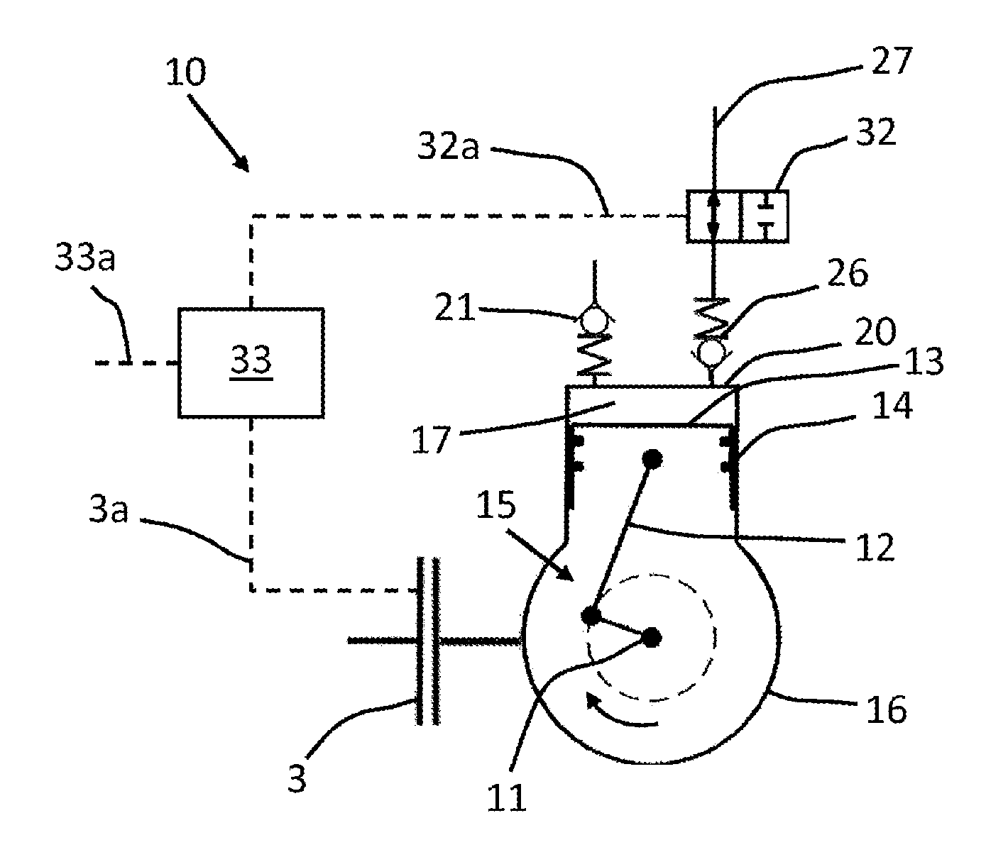
[0026] FIG. 4 is a schematic illustration of a second exemplary embodiment of a piston compressor according to the invention, in which a switchable valve device forms the closing device.
DETAILED DESCRIPTION OF THE DRAWINGS
[0027] FIG. 1 is a schematic illustration of an exemplary piston compressor 10 such as is known in the prior art. The crankshaft 11 of the piston compressor 10 is connected via a clutch 3 to a drive device (not illustrated, in this case an internal combustion engine) and is selectively separable from said drive device by way of the clutch 3. When the clutch 3 is open, it is thus the case that no torque is transmitted to the crankshaft 11 of the piston compressor 10, such that the crankshaft 11 is stationary during the separation of the piston compressor 10 from the drive device.
[0028] The crankshaft 11 is connected to a connecting rod 12 which is mounted eccentrically on said crankshaft, on which connecting rod there is mounted a piston 13. The piston 13 is mounted in axially movable fashion in a cylinder 14 of the piston compressor 10. The crank drive 15, which has at least one crankshaft 11, a connecting rod 12 and a piston 13, is arranged in a crankcase 16, which is fixedly connected to the cylinder 14. By means of a rotational movement of the crankshaft 11, the piston 13 is moved by the connecting rod 12 in the cylinder 14 so as to perform a reciprocating movement.
[0029] Above the piston 13, the cylinder 14 is closed off by a valve plate 20. Thus, the cylinder 14, the piston 13 and the valve plate 20 define the compression chamber 17 in the cylinder 14. On the valve plate 20, there is arranged an inlet valve 21 which is arranged between an inlet line 22 and the compression chamber 17. The inlet line 22 is part of an inlet system 23 which draws fresh air from the surroundings through a filter (not illustrated) and supplies said fresh air via the inlet line 22 through the cylinder head (not illustrated) to the compression chamber 17. The cylinder head is arranged above the valve plate 20 and has a cylinder head volume 24 which is connected via the inlet valve 21 to the compression chamber 17. Here, the inlet valve 21 is designed as a shut-off valve which allows fresh air to be drawn into the compression chamber 17 but prevents a backflow of the air that has been drawn into the compression chamber 17 via the inlet line 22.
[0030] Also arranged on the valve plate 20 is an outlet valve 26, which is arranged between the compression chamber 17 and an outlet line 27. Via the outlet line 27, compressed gas, in this case air, is supplied to a compressed-air accumulator (not illustrated here). Here, the outlet valve 26, which is likewise designed as a shut-off valve, prevents a backflow of compressed air from the outlet line 27 into the compression chamber 17.
[0031] FIG. 2 is an illustration of an exemplary outlet valve 26 such as is commonly used in piston compressors 10 in the prior art. The outlet valve 26 is arranged on the valve plate 20 of the piston compressor 10 above the compression chamber 17. The valve plate 20 has an outlet opening 28 which connects the compression chamber 17 to a cylinder head volume 27a arranged in the valve plate 20 and cylinder head of the piston compressor 10, which cylinder head volume is connected to the outlet line 27.
[0032] The outlet valve 26 has, as a valve body, a valve tongue 26a which, above a predetermined pressure difference between the compression chamber 17 and the outlet line 27, lifts off from the valve seat 26b and permits a throughflow of air from the compression chamber 17 into the outlet line 27. The outlet valve 26 furthermore has an abutment element 26c which is arranged above the outlet opening 28 and against which the valve tongue 26a bears in the open state. As soon as the valve tongue 26a lifts off from the valve seat 26b, the pressurized air can flow from the compression chamber 17 through the lateral open regions past the valve tongue 26a and the abutment element 26c into the outlet line 27.
[0033] If contaminants from the compression chamber 17 or from the cylinder head volume 27a, which contaminants detach for example from coatings that are formed by residues in the throughflowing air from the hot top side of the piston 13, from the valve plate 20 or from the cylinder head volume 27a, pass between the valve tongue 26a and the valve seat 26b, there is the risk that the outlet valve 26 no longer completely closes. In this case, compressed air can flow from the outlet line 27 back into the compression chamber 17 as soon as the pressure in the compression chamber 17 is lower than the pressure in the outlet line 27. In the case of a 12.5 bar compressed-air system of a commercial vehicle, the compression chamber 17 of the piston compressor 10 may for example be charged with a pressure of up to 6 bar by the air flowing back into it. If the piston compressor 10 is then connected to the drive device again, the piston compressor 10 generates an internal pressure of up to 60 bar during the first stroke. If the compression chamber 17 withstands this enormous internal pressure, the torque that is generated here at the crankshaft 11 is normally far too high for the clutch 3, such that the latter slips, overheats, and is subject to excessively rapid wear.
[0034] FIG. 3 is a schematic illustration of a first exemplary embodiment of a piston compressor 10 according to the invention. The construction of the piston compressor 10 in FIG. 3 corresponds substantially to the construction of the piston compressor 10 illustrated in FIG. 1 and described with regard thereto, such that identical elements of the piston compressors 10 are denoted by the same reference designations. Below, only the differences between the piston compressor 10 from FIG. 3 and the piston compressor 10 from FIG. 1 will be discussed.
[0035] The piston compressor 10 illustrated in FIG. 3 has a closing device in the form of a shut-off valve, which is arranged separately downstream of the outlet valve 26 in the flow direction. The shut-off valve is designed as a check valve 31 with preloaded valve body. This check valve 31 opens when the pressure of the air which is discharged by the piston compressor 10, and which flows out of the compression chamber 17 through the outlet valve 26, is higher, by a magnitude, than the pressure of the air that is situated in the outlet line 27. The magnitude of the pressure difference is at least so great that the preload of the check valve 31 is overcome, in order that the check valve 31 opens.
[0036] While the piston compressor 10 is at a standstill, no compressed air is situated in the compression chamber 17. Even if the outlet valve 26 does not reliably close, no compressed air can flow from the pressurized outlet line 27 back into the compression chamber 17, because the outlet line is closed off with respect to the compression chamber 17 by the check valve 31. During compression operation of the piston compressor 10, compressed air, which is at a higher pressure than the compressed air in the outlet line 27, is conveyed through the outlet valve 26. Owing to the pressure difference between the air discharged from the compression chamber 17 and the pressure in the outlet line 27, the check valve 31 opens, and the compressed air is supplied to the outlet line 27 and thus to the compressed-air system.
[0037] FIG. 4 is a schematic illustration of a second exemplary embodiment of a piston compressor 10 according to the invention. The construction of the piston compressor 10 in FIG. 4 also substantially corresponds to the construction of the piston compressor 10 illustrated in FIG. 1 and described with regard thereto, such that identical elements of the piston compressors 10 are denoted by the same reference designations. Only the differences between the piston compressor 10 from FIG. 4 and the piston compressor 10 from FIG. 1 will be discussed below.
[0038] The piston compressor 10 illustrated in FIG. 4 has a closing device in the form of a switchable valve device 32 which is arranged separately downstream of the outlet valve 26 in the flow direction. The switchable valve device 32 is, in the exemplary embodiment, designed as a 2/2-way valve, which is switchable from a closed position into the illustrated open position. The switchable valve device 32 is connected via a control line 32a to a control device 33, which opens and closes the switchable valve device 32 by means of switching signals transmitted via the control line 32a. In the exemplary embodiment, the control device 33 is furthermore connected via a control line 3a to the clutch 3, wherein signals regarding the switching position of the clutch 3 are transmitted by the control line 3a to the control device 33. The control device 33 is optionally connected via a control line 33a to the controller of the compressed-air system.
[0039] While the piston compressor 10 is at a standstill--the clutch between the drive device and the piston compressor 10 is open--the switchable valve device 32 is switched into the closed position. Even if the outlet valve 26 does not reliably close, no compressed air can flow from the pressurized outlet line 27 back into the compression chamber 17, because the outlet line 27 is closed off with respect to the compression chamber 17 when the switchable valve device 32 is in the closed position. Upon the closure of the clutch 3 at the start of compression operation of the piston compressor 10, the switchable valve device 32 is switched into the open position shown in FIG. 4. In this way, compressed air which is at a higher pressure than the compressed air in the outlet line 27 can be conveyed through the outlet valve 26, and through the switchable valve device 32 which is situated in the open position, into the outlet line 27, and supplied to the compressed-air system. Optionally, in a variant in which the control device 33 is connected to the controller of the compressed-air system, the opening of the clutch 3 may take place simultaneously with the switching of the switchable valve device 32 into the closed position, and the closing of the clutch 3 may take place simultaneously with the switching of the switchable valve device 32 into the open position.
LIST OF REFERENCE DESIGNATIONS
[0040] 3 Clutch [0041] 3a Control line [0042] 10 Piston compressor [0043] 11 Crankshaft [0044] 12 Connecting rod [0045] 13 Piston [0046] 14 Cylinder [0047] 15 Crank drive [0048] 16 Crankcase [0049] 17 Compression chamber [0050] 20 Valve plate [0051] 21 Inlet valve [0052] 22 Inlet line [0053] 23 Inlet system [0054] 24 Cylinder head volume (inlet) [0055] 26 Outlet valve [0056] 26a Valve tongue [0057] 26b Valve seat [0058] 26c Abutment element [0059] 27 Outlet line [0060] 28 Outlet opening [0061] 31 Shut-off valve [0062] 32 Switchable valve device [0063] 32a Control line [0064] 33 Control device [0065] 33a Control line
[0066] The foregoing disclosure has been set forth merely to illustrate the invention and is not intended to be limiting. Since modifications of the disclosed embodiments incorporating the spirit and substance of the invention may occur to persons skilled in the art, the invention should be construed to include everything within the scope of the appended claims and equivalents thereof.
* * * * *
D00000
D00001
D00002
XML
uspto.report is an independent third-party trademark research tool that is not affiliated, endorsed, or sponsored by the United States Patent and Trademark Office (USPTO) or any other governmental organization. The information provided by uspto.report is based on publicly available data at the time of writing and is intended for informational purposes only.
While we strive to provide accurate and up-to-date information, we do not guarantee the accuracy, completeness, reliability, or suitability of the information displayed on this site. The use of this site is at your own risk. Any reliance you place on such information is therefore strictly at your own risk.
All official trademark data, including owner information, should be verified by visiting the official USPTO website at www.uspto.gov. This site is not intended to replace professional legal advice and should not be used as a substitute for consulting with a legal professional who is knowledgeable about trademark law.