Deployment Of A Modular Electrically Driven Pump In A Well
Head; Philip ; et al.
U.S. patent application number 16/066426 was filed with the patent office on 2019-01-17 for deployment of a modular electrically driven pump in a well. The applicant listed for this patent is Coreteq Systems Ltd.. Invention is credited to Philip Head, Hassan Mansir.
| Application Number | 20190017357 16/066426 |
| Document ID | / |
| Family ID | 55359123 |
| Filed Date | 2019-01-17 |
| United States Patent Application | 20190017357 |
| Kind Code | A1 |
| Head; Philip ; et al. | January 17, 2019 |
DEPLOYMENT OF A MODULAR ELECTRICALLY DRIVEN PUMP IN A WELL
Abstract
An electric submersible pump system comprises an electric submersible pump body (50) having a first mating profile (53), an electric submersible pump motor (54) having a second mating profile (55), and an electrical wet connect point (61) at the top of the electric submersible pump. The electric submersible pump body (50) has a first mating drive shaft, and the electric submersible pump motor (54) has a second mating drive shaft, such that first and second mating drive shafts engage and can transmit torque from one drive shaft to the other.
| Inventors: | Head; Philip; (Virginia Water Surrey, GB) ; Mansir; Hassan; (Maidenhead Birkshire, GB) | ||||||||||
| Applicant: |
|
||||||||||
|---|---|---|---|---|---|---|---|---|---|---|---|
| Family ID: | 55359123 | ||||||||||
| Appl. No.: | 16/066426 | ||||||||||
| Filed: | January 2, 2017 | ||||||||||
| PCT Filed: | January 2, 2017 | ||||||||||
| PCT NO: | PCT/GB2017/050001 | ||||||||||
| 371 Date: | June 27, 2018 |
| Current U.S. Class: | 1/1 |
| Current CPC Class: | F04D 13/10 20130101; E21B 17/028 20130101; F04D 29/628 20130101; E21B 43/128 20130101 |
| International Class: | E21B 43/12 20060101 E21B043/12; E21B 17/02 20060101 E21B017/02; F04D 13/10 20060101 F04D013/10; F04D 29/62 20060101 F04D029/62 |
Foreign Application Data
| Date | Code | Application Number |
|---|---|---|
| Dec 27, 2015 | GB | 1522999.0 |
Claims
1. An electric submersible pump system comprising an electric submersible pump body having a first mating profile an electric submersible pump motor having a second mating profile an electrical wet connect point at the top of the electric submersible pump.
2. An electric submersible pump system according to claim 1, wherein the electric submersible pump body has a first mating drive shaft, and the electric submersible pump motor has a second mating drive shaft, such that first and second mating drive shafts engage and can transmit torque from one drive shaft to the other.
3. An electric submersible pump system according to claim 1, further comprising a sub surface safety valve above the electric submersible pump.
4. An electric submersible pump system according to claim 1, further comprising a cable terminating with a wet connector.
5. An electric submersible pump system according to claim 4, wherein cable comprises a plurality of conductors, and at least one reinforced longitudinal tensile member, such as polymer fibres or steel strands.
6. A length of downhole cable according to claim 5.
7. A method for installing electric submersible pump comprising the steps of deploying an electric submersible pump having a first electrical wet connector separately deploying a power cable having a second wet connector which mates with the first electrical wet connector.
8. A method according to claim 7, wherein the step of deploying an electric submersible pump comprises the substeps of deploying an electric submersible pump body separately deploying an electric submersible pump motor
Description
TECHNICAL FIELD
[0001] This invention relates to a method of deploying a modular electrical submersible powered fluid transducer system, such as a gas compressor or an electrical submersible pump, generally known as an ESP, in an oil and/or gas production well.
BACKGROUND ART
[0002] The disposing in wells of electrical submersible systems has been done for many years using jointed tubular conduits with an electrical motor, and a fluid transducer connected to the bottom of the jointed tubing. Consecutive joints of tubular conduits are connected and lowered into a well with the assistance of a rig mast and hoisting equipment, whilst unspooling and connecting to the outer diameter of the tubing a continuous length of electrical power transmission cable. This method of disposing the electrical submersible fluid transducer system is well know to those familiar with the art of producing non-eruptive sources of oil and gas from the subterranean environment. The retrieval of these electrical submersible fluid transducer systems is also commonly accomplished by pulling the jointed tubing out of the well simultaneously with the electrical submersible motor and fluid transducer system and the electrical power transmission cable. The following prior art references are believed to be pertinent to the invention claimed in the present application: U.S. Pat. Nos. 3,939,705; 4,105,279; 4,494,602; 4,589,717; 5,180,140; 5,746,582 and 5,871,051; International patent application No. WO98122692 and European patent specifications Nos. 470576 and 745176. U.S. Pat. Nos. 3,835,929, 5,180,140 and 5,191,173 teach the art of deploying and retrieving an electrical submersible system in oil wells using coiled or continuous tubing. These coiled tubing disposal methods often use large coiled tubing spool diameters owing to the radius of curvature possible of the continuous tubing. Hence the surface spooling devices that these systems require to inject and retrieve the continuous tubing are cumbersome, and require special surface and subterranean equipment for deployment and intervention.
[0003] Other previous art disclosed in the literature teaches the disposal and retrieval of the subterranean electrical fluid transducer system with wireline or wire rope as structural support for simultaneously disposing the electrical power transmission cable with the system. Hence these wireline methods and apparatus involve the use of large and unique surface intervention equipment to handle the weight and spool used for the electrical power cable and the wire rope to be run in the well. U.S. Pat. No. 5,746,582 discloses the retrieval of a submersible pumps whilst leaving an electrical motor and cable in a well. Hence the method of U.S. Pat. No. 5,746,582 teaches the retrieval and deployment of the mechanical portion of an electrical submersible fluid transmission system whilst leaving the electrical motor and other component parts of the electrical submersible system disposed in the disposal of the electrical motor separately from the electrical power transmission cable. In the case of artificially lifted wells powered with electrical submersible motor systems, the current art is to dispose the required transducer assembly, for example a pump or compressor assembly, with an electrical motor and electrical power cable simultaneously into the well with a supporting member. This supporting member is jointed tubing from a surface rig, a coiled tubing unit with continues tubing or braided cable. The tubing or a braided cable is required as the electrical power cable is not able to support its own weight in the well and hence must be connected and disposed in the well with a structural member for support. In the case of jointed pipe deployed from a rig, the power cable is attached to the electrical motor on surface, and the cable is attached to the tubing as the electrical motor, transducer, and tubing are disposed into the well casing or tubing. The attachment of the cable to the tube is done by the use of steel bands, cast clamps, and other methods known to those familiar with the oil and gas business. In other methods, the power cable is placed inside of continuous tubing or attached to the outside of continuous tubing with bands as taught by U.S. Pat. No. 5,191,173. This continuous tubing is often referred to in the industry as coiled tubing. U.S. Pat. No. 3,835,929 teaches the use of the continuous tubing with the electrical power transmission cable inside of the tube. In all cases where electrical submersible fluid transducers systems are disposed and retrieved from wells the electric motor and electrical power transmission cable are deployed or retrieved simultaneously.
[0004] It is well known to those familiar with electrical submersible power cable that the action of removing the cable from the well can result in damage to the electrical power transmission cable, in a variety of ways. The damage inflicted on the electrical power cable can be due to bending stresses imposed on the cable during the disposal and retrieval. The conventional electrical power cable insulation, wrapping, and shields can develop stress cracks from the spooling of the cable over sheaves and spools devices used to deploy the cable. Another failure mode associated with submersible power transmission cable is caused from impact loads or crushing of the cable as it is disposed or retrieved in the well. It is also well known that gases found in subterranean environments impregnated the permeability of the electrical power transmission cable's insulation, wrapping and shields. This gas is trapped in the permeability of the insulation at a pressure similar to the pressure found inside the well. When the cable is retrieved from the well the electrically powered transmission cable is exposed to ambient pressures. This will create a pressure differential between gas encapsulated in the cable insulation and the ambient surface pressure conditions. The rate of impregnated gas expansion from the higher pressure inside of the cable insulation expanding towards the lower pressure of the ambient conditions can sometimes exceed the cable insulation permeability's ability to equalise the pressure differential. The result is a void, or stressing of the insulation, and premature failure of the cable. The requirement to retrieve and dispose the electrical power transmission cable with the electrical submersible fluid traducer system also requires the use of specialised surface intervention equipment. This can require very large rigs, capable of pulling tubing, electrical power transmission cable, and electrical submersible fluid transducers. In the offshore environment these well intervention methods require semi-submersible drill ships and platforms. In the case of jointed conduit deployed in a plurality of threaded lengths, normally 9-12 m each, the pulling equipment is a drilling or pulling rig at surface. In the case that the electrical power transmission cable and assembly are disposed connected to or in continuous tubing, a specialised coiled tubing rig is required at surface. This coiled tubing unit consisting of an injector head, a hydraulic power unit, and a large diameter spooling device containing the continuous coiled tubing all located on the surface. This disposal and retrieval method requires significant space at the earth's surface or sea floor. The reasons for intervening in a well to retrieve or dispose an electrical submersible transducer system are well know to those familiar with the art of fluid removing fluids from wells. There are at least two classical reasons for intervention in wells disposed with electrical submersible fluid transducer systems. These include the need to increase fluid production, or the need to repair the disposed electrical submersible power system. The reason for requiring increased fluid production is dependent on many factors including but not limited to economical and reservoir management techniques discussed in the literature. The reasons for intervening for repair or to replace the electrical submersible fluid transducer systems are due to normal equipment wear and the subsequent loss of fluid production capacity, catastrophic equipment failure, and changes in the fluid production capacity of the subterranean fluid reservoir. The equipment failures can be caused due to subterranean electrical failures in the electrical motor windings, electrical motor insulation degradation due to heat or mechanical wear, conductive fluid leaking into the motor, wear or failure of the fluid transducer parts, wear of electrical motor bearings, shaft vibrations, changes in inflow performance of the reservoir, and other phenomena known to those familiar with the art of fluid production from wells. Therefore, it is often required to change out component parts of the electrical submersible fluid transducer system, but not necessarily the electrical power transmission cable. However, owing to prior art the power cable is retrieved when the electrical motor or the motor seals fail.
DISCLOSURE OF INVENTION
[0005] The primary object of the present invention is to provide a convenient system for deploying electric pumps downhole.
[0006] According to the present invention, there is provided a system for installing electric submersible pump with a electrical wet connector, then deploying the power cable separately with the other half of the electrical wet connector.
[0007] According to another aspect of the invention, the ESP assembly could include a sub surface safety valve, enabling the well to safely sealed in the event of some failure at or near surface.
[0008] According to another aspect of the invention the cable to deploy the ESP would only have to carry the weight of the ESP assembly. The cable incorporating the electrical conductors would only have to carry its own weight and that of the upper half of the electrical we connector.
[0009] According to another aspect of the invention, the power cable would have a strong tensile member designed to endure long life in a well, unlike conventional braided wireline.
BRIEF DESCRIPTION OF DRAWINGS
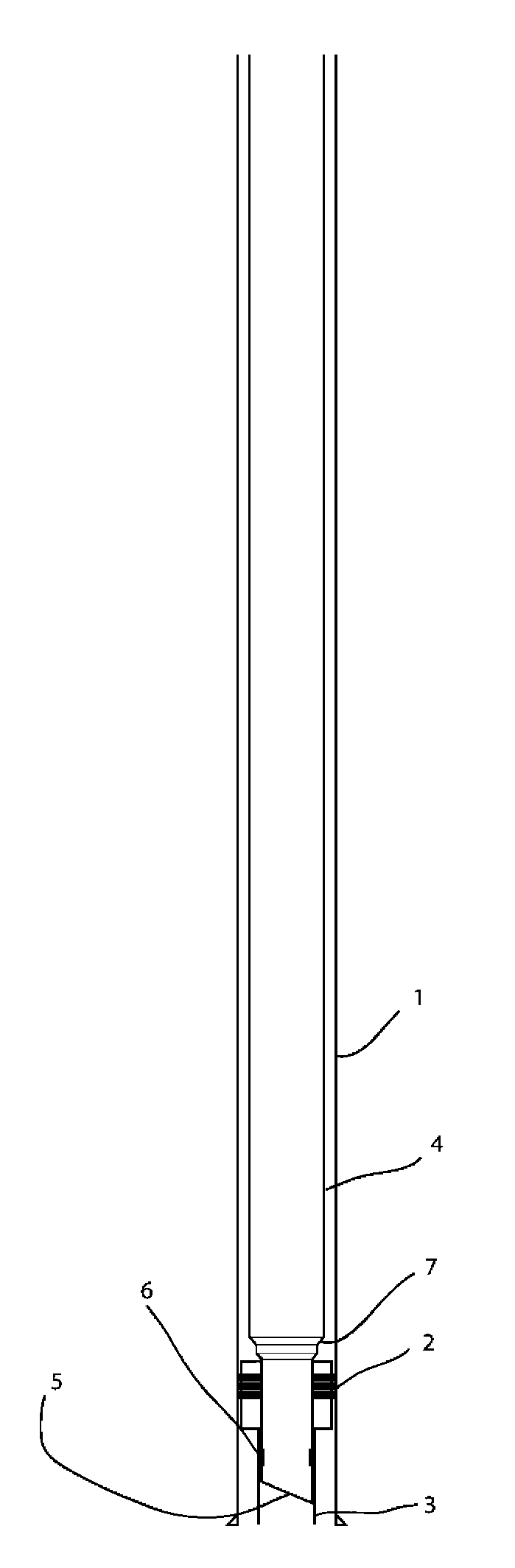
[0010] FIG. 1 shows a side view of an oil well, with production tubing with stinger tube, a packer set in the casing with a polished bore receptacle.
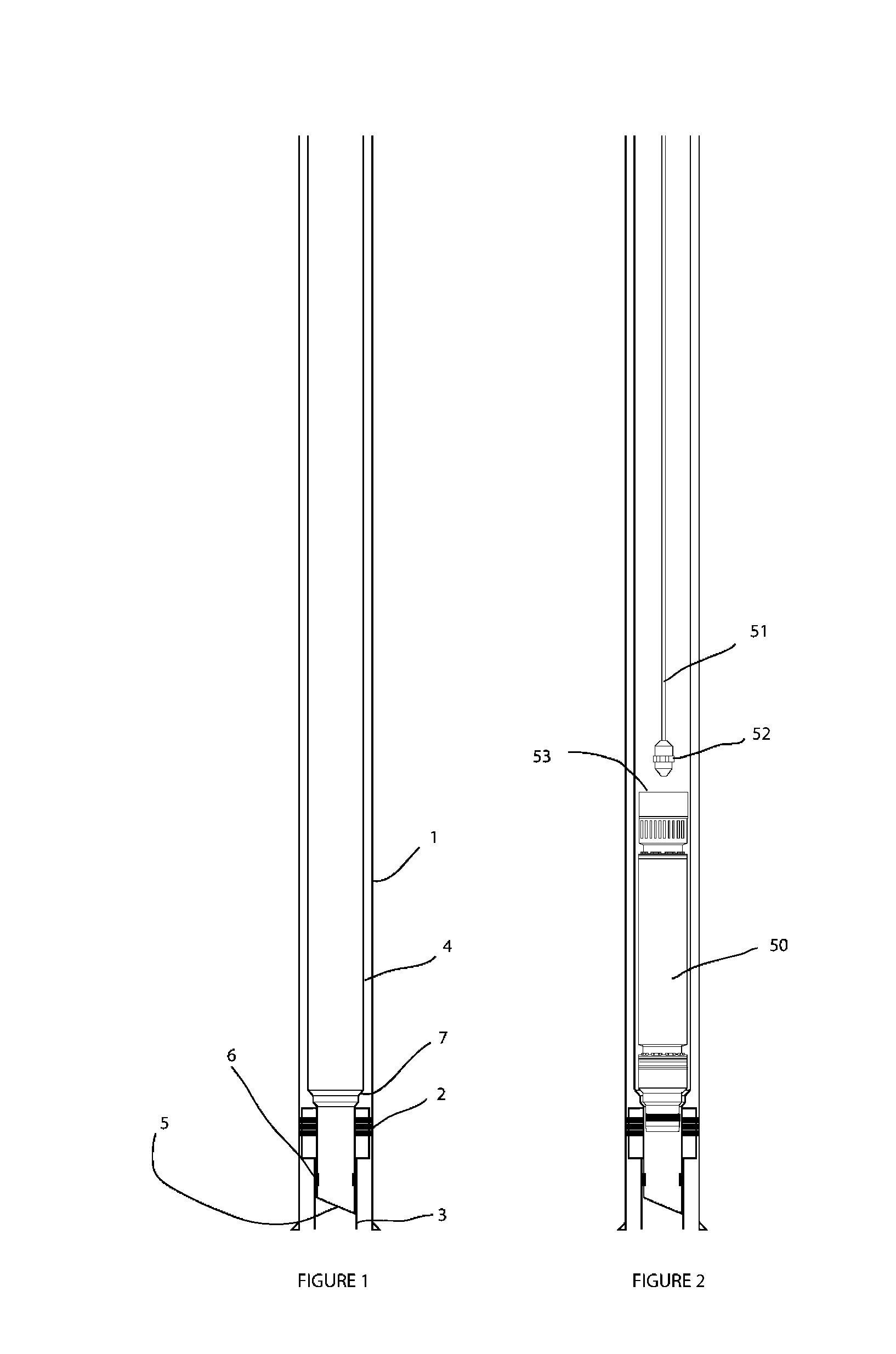
[0011] FIG. 2 shows a similar view to FIG. 1, with the pump section of the electrical submersible pump positioned in the lowermost part of the production tubing, the deployment cable disconnected.
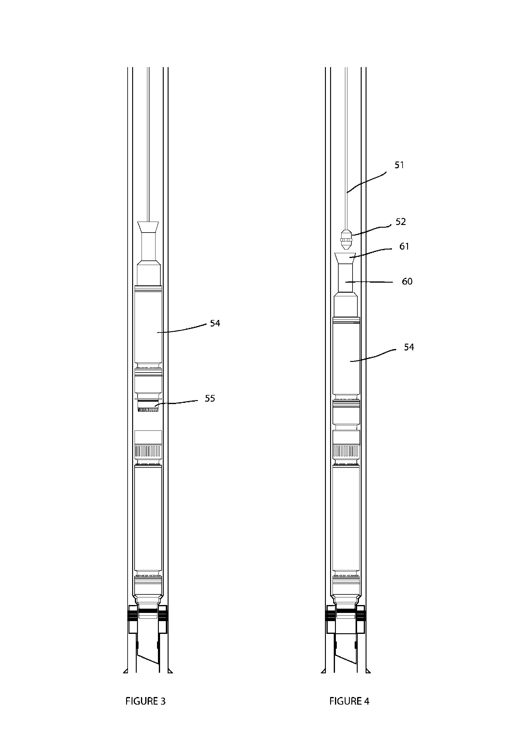
[0012] FIG. 3 shows a similar view to FIG. 2 with the motor section of an electrical submersible pump being lowered on a cable into the well
[0013] FIG. 4 shows a similar view to FIG. 3 with the electric motor docked to the pump and the deployment cable disconnected.
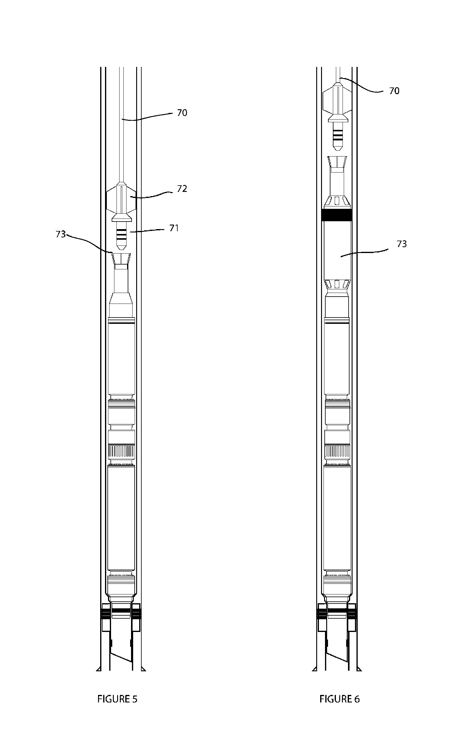
[0014] FIG. 5 shows a similar view to FIG. 4 with a power cable above the electrical submersible pump and the electrical wet connect termination on its lower most part about to be docked into the other half of the wet electrical connector which is at the top of the ESP assembly.
[0015] FIG. 6 is a similar view to FIG. 5, with the addition of a sub surface safety valve (SSSV) located between the electric motor and the lower half of the electrical wet connector.
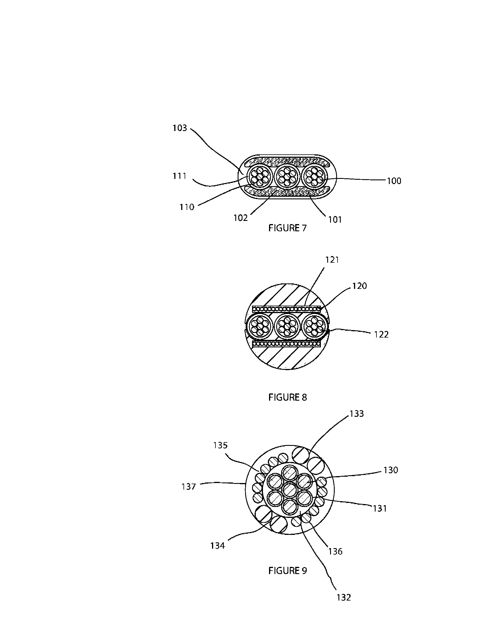
[0016] FIG. 7 is a cross section of one embodiment of the power cable
[0017] FIG. 8 is a cross section of another embodiment of the power cable
[0018] FIG. 9 is a cross section of a further embodiment of the power cable
BEST MODE FOR CARRYING OUT THE INVENTION
[0019] Referring to FIGS. 1 to 6, there is shown a well completion with casing 1 cemented into the wellbore. A packer 2 is set in the casing which includes a polished bore receptacle (PBR) 3. The production tubing 4 stings into the PBR with a stinger 5 and seal 6. The production tubing includes other features which enable the electrical powered device to be installed and operated, these will now be described.
[0020] A no-go 7 landing shoulder feature is included to provide a reference stop point when installing the pump section 50 of the electrical submersible pump system. The pump section is lowered into the well on a strong cable 51 with a tool called a GS running tool 52 (available from Otis Engineering Corp). Inside the uppermost end of the pump is a splined drive for the pump, and lower mating unit 53.
[0021] The next module to be installed is the electric motor 54 which consists of the upper half of the mating unit 55, as the motor 54 engages with the pump 50, the lower half 53 and upper half 55 of the mating unit engage and lock the housings and the drive shafts together. Any suitable type of pump may be utilised in the lower half of the mating unit, for example an impeller pump.
[0022] At the upper end of the electric motor, is the lower half of the electrical wet connector 60. It is also lowered into the well on a strong cable 51 with a tool called a GS running tool 52. Inside the upper most end of the electric motor module 54 is a profile 62 in which the GS running tool is engaged.
[0023] Finally a power cable 70 is lowered in to the well terminated with the upper half of the three phase electrical wet connector 71, it also has centraliser fins 72 to keep it centralised in the production tubing 4. It is guided into the bore by a funnel arrangement 73 inside which is located the lower half of the 3 phase electrical wet connector 60. The benefit of this arrangement is the power cable 70 only has to support the weight of itself and the lower termination 71.
[0024] In the situation where a sub-surface safety valve (SSSV) 73 is required, this would be fitted between the top of the motor and the bottom of the lower electrical wet connector,
[0025] Referring to FIGS. 7 to 9 are various embodiments to the power cable.
[0026] These are designed to be very flexible in the horizontal axis, so that they can bend over the sheave wheels of a typical wire line surface rig.
[0027] The power cable 100 is multi stranded to again assist in flexibility and has a primary 110 and secondary 111 electrical insulation coatings. The power cables are sandwiched between two profiled tensile members 101, which are reinforced with polyester fibres, which are both lightweight and strong, They also protect the power cables from any side impacts or as they as the cable passes over the sheave wheels. An elastomer jacket 103 holds the assembly together.
[0028] An alternative tensile member is shown in FIG. 8. In this embodiment the tensile support members are made from high tensile strength steel stands 120 bonded in a flat jacket 121 to hold them together. Two of these are used to sandwich the power cables 122, an elastomer outer jacket 123 is used to hold the cable assembly together.
[0029] A further embodiment of the cable consists of a multi stranded core 130 of copper clad steel, 131 which is insulated by a jacket 132. This performs two functions, supports the weight of the cable and provides one phase of the three phase supply. Around the outside of this core, is a second layer wound in the opposite helix to the inner core, this outer layer has two larger kelvar wires 133, 134 which perform three functions, the first is to be a reactive force to the torque generated by the inner core, the second is to be proud of the electrical conductors 135, 136 to provide some mechanical protection and the third is electrical separate the other two phases 135 and 136. The wire 135 and 136 are just copper. Finally a jacket 137 encapsulates the entire assembly.
* * * * *
D00000
D00001
D00002
D00003
D00004
XML
uspto.report is an independent third-party trademark research tool that is not affiliated, endorsed, or sponsored by the United States Patent and Trademark Office (USPTO) or any other governmental organization. The information provided by uspto.report is based on publicly available data at the time of writing and is intended for informational purposes only.
While we strive to provide accurate and up-to-date information, we do not guarantee the accuracy, completeness, reliability, or suitability of the information displayed on this site. The use of this site is at your own risk. Any reliance you place on such information is therefore strictly at your own risk.
All official trademark data, including owner information, should be verified by visiting the official USPTO website at www.uspto.gov. This site is not intended to replace professional legal advice and should not be used as a substitute for consulting with a legal professional who is knowledgeable about trademark law.