Vehicle Cover Assembly
CHEN; Jack
U.S. patent application number 15/652222 was filed with the patent office on 2019-01-17 for vehicle cover assembly. This patent application is currently assigned to SPORTSMAN CORPORATION. The applicant listed for this patent is Jack CHEN. Invention is credited to Jack CHEN.
| Application Number | 20190017322 15/652222 |
| Document ID | / |
| Family ID | 64998812 |
| Filed Date | 2019-01-17 |


| United States Patent Application | 20190017322 |
| Kind Code | A1 |
| CHEN; Jack | January 17, 2019 |
VEHICLE COVER ASSEMBLY
Abstract
A vehicle cover assembly has a body and a lock device. The body has a housing, a reeling device, and a cover fabric. The reeling device is mounted in the housing and has a reeling axle. The cover fabric is connected with and is selectively reeled around the reeling axle. The lock device has a casing, a pushing rod, and a lock cylinder. The casing is mounted on the housing. The pushing rod is moveably mounted through the casing and has an end selectively engaged with one end of the reeling axle. The lock cylinder is mounted in the casing and is selectively engaged with the pushing rod. When the lock cylinder is engaged with the pushing rod, the pushing rod is engaged with the reeling axle.
| Inventors: | CHEN; Jack; (NEW TAIPEI, TW) | ||||||||||
| Applicant: |
|
||||||||||
|---|---|---|---|---|---|---|---|---|---|---|---|
| Assignee: | SPORTSMAN CORPORATION NEW TAIPEI TW |
||||||||||
| Family ID: | 64998812 | ||||||||||
| Appl. No.: | 15/652222 | ||||||||||
| Filed: | July 17, 2017 |
| Current U.S. Class: | 1/1 |
| Current CPC Class: | E05B 37/02 20130101; E04F 10/0666 20130101; E06B 2009/802 20130101; E06B 9/80 20130101; E04F 10/06 20130101; E05B 65/006 20130101; B60J 11/02 20130101 |
| International Class: | E06B 9/80 20060101 E06B009/80; B60J 11/02 20060101 B60J011/02; E05B 37/02 20060101 E05B037/02; E05B 65/00 20060101 E05B065/00 |
Claims
1. A vehicle cover assembly comprising: a body having a housing; a reeling device mounted in the housing and having a reeling axle; a cover fabric connected with and selectively reeled around the reeling axle; and a lock device having a casing mounted on the housing; a pushing rod moveably mounted through the casing and having an end selectively engaged with one end of the reeling axle; and a lock cylinder mounted in the casing and selectively engaged with the pushing rod, wherein when the lock cylinder is engaged with the pushing rod, the pushing rod is engaged with the reeling axle.
2. The vehicle cover assembly as claimed in claim 1, wherein the pushing rod has a groove longitudinally defined in an outer surface of the pushing rod and having an end being adjacent to the reeling axle and extending laterally along a periphery of the pushing rod; and the casing further has a through hole and a protrusion formed on the through hole and extending slidably into the groove in the pushing rod.
3. The vehicle cover assembly as claimed in claim 1, wherein the reeling axle has multiple engaging recesses arranged annularly; and the pushing rod has a first rod body mounted through the casing; a second rod body having a first end moveably connected with the first rod body, a second end selectively engaged with one of the engaging recesses of the reeling axle, and an inclined surface formed on the second end of the second rod body; and a resilient member having two ends connected respectively with the first rod body and the second rod body to push the second rod body to engage with one of the engaging recesses.
4. The vehicle cover assembly as claimed in claim 2, wherein the reeling axle has multiple engaging recesses arranged annularly; and the pushing rod has a first rod body mounted through the casing; a second rod body having a first end moveably connected with the first rod body, a second end selectively engaged with one of the engaging recesses of the reeling axle, and an inclined surface formed on the second end of the second rod body; and a resilient member having two ends connected respectively with the first rod body and the second rod body to push the second rod body to engage with one of the engaging recesses.
5. The vehicle cover assembly as claimed in claim 4, wherein the first rod body of the pushing rod has a main body segment mounted through the casing; and a connection segment formed on an end of the main body segment adjacent to the reeling device; the second rod body of the pushing rod is moveably mounted around the connection segment of the first rod body and has at least one channel defined longitudinally in the second rod body; and the pushing rod further has a positioning element securely mounted on the connection segment of the first rod body and having at least one end held respectively in the at least one channel in the second rod body.
6. The vehicle cover assembly as claimed in claim 5, wherein the pushing rod has an annular flange formed around the pushing rod and having a conical surface formed on a side of the annular flange opposite the reeling device; and the lock cylinder selectively abuts one of a periphery and the conical surface of the annular flange.
7. The vehicle cover assembly as claimed in claim 3, wherein the first rod body of the pushing rod has a main body segment mounted through the casing; and a connection segment formed on an end of the main body segment adjacent to the reeling device; the second rod body of the pushing rod is moveably mounted around the connection segment of the first rod body and has at least one channel defined longitudinally in the second rod body; and the pushing rod further has a positioning element securely mounted on the connection segment of the first rod body and having at least one end held respectively in the at least one channel in the second rod body.
8. The vehicle cover assembly as claimed in claim 7, wherein the pushing rod has an annular flange formed around the pushing rod and having a conical surface formed on a side of the annular flange opposite the reeling device; and the lock cylinder selectively abuts one of a periphery and the conical surface of the annular flange.
9. The vehicle cover assembly as claimed in claim 4, wherein the pushing rod has an annular flange formed around the pushing rod and having a conical surface formed on a side of the annular flange opposite the reeling device; and the lock cylinder selectively abuts one of a periphery and the conical surface of the annular flange.
10. The vehicle cover assembly as claimed in claim 3, wherein the pushing rod has an annular flange formed around the pushing rod and having a conical surface formed on a side of the annular flange opposite the reeling device; and the lock cylinder selectively abuts one of a periphery and the conical surface of the annular flange.
11. The vehicle cover assembly as claimed in claim 2, wherein the pushing rod has an annular flange formed around the pushing rod and having a conical surface formed on a side of the annular flange opposite the reeling device; and the lock cylinder selectively abuts one of a periphery and the conical surface of the annular flange.
12. The vehicle cover assembly as claimed in claim 1, wherein the pushing rod has an annular flange formed around the pushing rod and having a conical surface formed on a side of the annular flange opposite the reeling device; and the lock cylinder selectively abuts one of a periphery and the conical surface of the annular flange.
13. The vehicle cover assembly as claimed in claim 12, wherein the lock cylinder is mounted in the casing and comprises a movable axle having a pushing end selectively abutting against the pushing rod; multiple wheels rotatably mounted around the moveable axle and each of the wheels partially exposed from the casing; and a resilient member connected with the pushing end of the moveable axle to push the pushing end to abut against the pushing rod.
14. The vehicle cover assembly as claimed in claim 11, wherein the lock cylinder is mounted in the casing and comprises a movable axle having a pushing end selectively abutting against the pushing rod; multiple wheels rotatably mounted around the moveable axle and each of the wheels partially exposed from the casing; and a resilient member connected with the pushing end of the moveable axle to push the pushing end to abut against the pushing rod.
15. The vehicle cover assembly as claimed in claim 10, wherein the lock cylinder is mounted in the casing and comprises a movable axle having a pushing end selectively abutting against the pushing rod; multiple wheels rotatably mounted around the moveable axle and each of the wheels partially exposed from the casing; and a resilient member connected with the pushing end of the moveable axle to push the pushing end to abut against the pushing rod.
16. The vehicle cover assembly as claimed in claim 9, wherein the lock cylinder is mounted in the casing and comprises a movable axle having a pushing end selectively abutting against the pushing rod; multiple wheels rotatably mounted around the moveable axle and each of the wheels partially exposed from the casing; and a resilient member connected with the pushing end of the moveable axle to push the pushing end to abut against the pushing rod.
17. The vehicle cover assembly as claimed in claim 4, wherein the lock cylinder is mounted in the casing and comprises a movable axle having a pushing end selectively abutting against the pushing rod; multiple wheels rotatably mounted around the moveable axle and each of the wheels partially exposed from the casing; and a resilient member connected with the pushing end of the moveable axle to push the pushing end to abut against the pushing rod.
18. The vehicle cover assembly as claimed in claim 3, wherein the lock cylinder is mounted in the casing and comprises a movable axle having a pushing end selectively abutting against the pushing rod; multiple wheels rotatably mounted around the moveable axle and each of the wheels partially exposed from the casing; and a resilient member connected with the pushing end of the moveable axle to push the pushing end to abut against the pushing rod.
19. The vehicle cover assembly as claimed in claim 2, wherein the lock cylinder is mounted in the casing and comprises a movable axle having a pushing end selectively abutting against the pushing rod; multiple wheels rotatably mounted around the moveable axle and each of the wheels partially exposed from the casing; and a resilient member connected with the pushing end of the moveable axle to push the pushing end to abut against the pushing rod.
20. The vehicle cover assembly as claimed in claim 1, wherein the lock cylinder is mounted in the casing and comprises a movable axle having a pushing end selectively abutting against the pushing rod; multiple wheels rotatably mounted around the moveable axle and each of the wheels partially exposed from the casing; and a resilient member connected with the pushing end of the moveable axle to push the pushing end to abut against the pushing rod.
Description
BACKGROUND OF THE INVENTION
1. Field of the Invention
[0001] The present invention relates to a vehicle cover assembly, and more particularly to a vehicle cover assembly having a lock device.
2. Description of Related Art
[0002] An indoor parking lot is a preferable location for vehicle-parking because the indoor parking lot can shade sunlight and rain. However, the indoor parking lot is a building that is costly to build, so to park indoors requires high cost. As the indoor parking lot cannot achieve all the parking needs, many vehicles are stilled parked in outdoor parking lots. In the outdoor parking lots, the vehicles are usually exposed to sunlight, rain, and wind, and further to dust storms in dry countries or snow in high latitude countries.
[0003] To protect the vehicle parked in an outdoor parking lot, a cover fabric is applied to cover the vehicle and to separate the vehicle from the outside environment. To conveniently expand and store the cover fabric, the cover fabric is usually reeled in a housing to form a vehicle cover assembly. When in use, the cover fabric is expanded from the housing to cover a vehicle. The cover fabric is connected with a reeling device that provides a torsion force to reel the cover fabric. Accordingly, when the cover fabric is detached from the vehicle, the cover fabric can be automatically reeled in the housing, such that any person, even an unauthorized person, can reel the cover fabric.
[0004] To overcome the shortcomings, the present invention tends to provide a vehicle cover assembly to mitigate or obviate the aforementioned problems.
SUMMARY OF THE INVENTION
[0005] The main objective of the invention is to provide a vehicle cover assembly that has a lock device to prevent a cover fabric from being reeled by any unauthorized person.
[0006] The vehicle cover assembly has a body and a lock device. The body has a housing, a reeling device, and a cover fabric. The reeling device is mounted in the housing and has a reeling axle. The cover fabric is connected with and is selectively reeled around the reeling axle. The lock device has a casing, a pushing rod, and a lock cylinder. The casing is mounted on the housing. The pushing rod is moveably mounted through the casing and has an end selectively engaged with one end of the reeling axle. The lock cylinder is mounted in the casing and is selectively engaged with the pushing rod. When the lock cylinder is engaged with the pushing rod, the pushing rod is engaged with the reeling axle.
[0007] Other objects, advantages and novel features of the invention will become more apparent from the following detailed description when taken in conjunction with the accompanying drawings.
BRIEF DESCRIPTION OF THE DRAWINGS
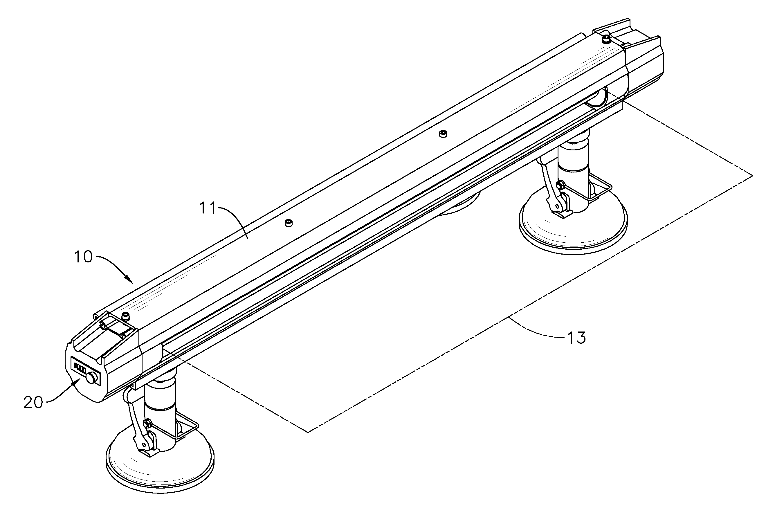
[0008] FIG. 1 is a perspective view of a vehicle cover assembly in accordance with the present invention;
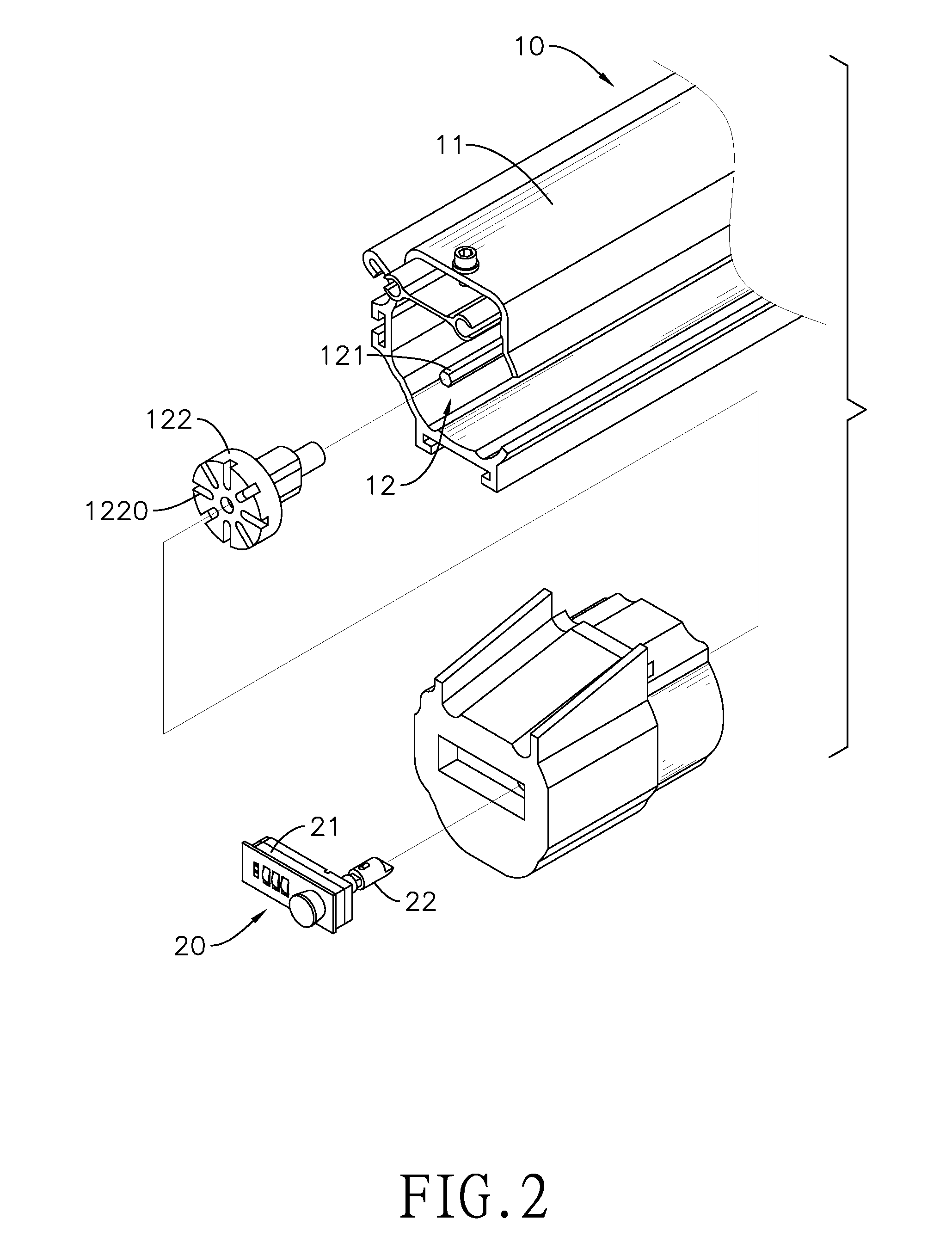
[0009] FIG. 2 is an enlarged exploded perspective view of the vehicle cover assembly in FIG. 1;
[0010] FIG. 3 is an enlarged exploded perspective view of the lock device of the vehicle cover assembly in FIG. 1;
[0011] FIG. 4 is an enlarged operational side view of the lock device of the vehicle cover assembly in FIG. 1;
[0012] FIG. 5 is another enlarged operational side view of the lock device of the vehicle cover assembly in FIG. 1;
[0013] FIG. 6 is an enlarged operational top view in partial section of the lock device of the vehicle cover assembly in FIG. 1; and
[0014] FIG. 7 is another enlarged operational top view in partial section of the lock device of the vehicle cover assembly in FIG. 1.
DETAILED DESCRIPTION OF PREFERRED EMBODIMENT
[0015] With reference to FIGS. 1 to 3, a vehicle cover assembly in accordance with the present invention comprises a body 10 and a lock device 20. The body 10 comprises a housing 11, a reeling device 12, and a cover fabric 13. The reeling device 12 is mounted in the housing 11 and has a reeling axle 121. The reeling axle 121 has a rotator 122, and multiple engaging recesses 1220 are defined in the rotator 122 and arranged annularly. Preferably, the rotator 122 is mounted on one end of the reeling axle 121, and the engaging recesses 1220 are defied in one side of the rotator 122. Alternatively, the rotator 122 can be mounted on a middle portion of the reeling axle 121, and the engaging recesses 1220 are defined in a periphery of the rotator 122.
[0016] The cover fabric 13 is connected with and selectively reeled around the reeling axle 121. The reeling device 12 may comprise a torsion unit to provide a torsion force to rotate the reeling axle 121 and to reel the cover fabric 13 around the reeling axle 121. Preferably, the torsion unit may be a torsion spring.
[0017] The lock device 20 comprises a casing 21, a pushing rod 22, and a lock cylinder 23. The casing 21 is mounted securely on the housing 11 and has a through hole 210 defined through the casing 21. A protrusion 211 is formed on and protrudes from an inner surface of the through hole 210 as shown in FIG. 6.
[0018] The pushing rod 22 is operationally mounted through the casing 21. Preferably, the pushing rod 22 is moveably mounted through the casing 21 along a longitudinal direction of the pushing rod 22 and is rotatable along an axis that is parallel with the longitudinal direction of the pushing rod 22. The pushing rod 22 has an end selectively engaged with the rotator 122. Preferably, the pushing rod 22 comprises a first rod body 221, a second rod body 222, a positioning element 223, a resilient member 224, and a rotating knob 225.
[0019] The first rod body 221 is mounted through the casing 21 and is moveable and rotatable relative to the casing 21. The first rod body 221 comprises a main body segment 2211, a groove 2212, an annular flange 2213, and a connection segment 2214.
[0020] The main body segment 2211 is mounted through the through hole 210 of the casing 21 and is selectively held in the through hole 210. With further reference to FIG. 6, the groove 2212 is longitudinally defined in an outer surface of the main body segment 2211, and the groove 2212 is selectively located in the through hole 210. The protrusion 211 in the through hole 210 extends into the groove 2212. The groove 2212 extends longitudinally along the longitudinal direction of the pushing rod 22 and has an end that is adjacent to the reeling axle 121 and extending laterally along a periphery of the pushing rod 22. Accordingly, the groove 2212 is L-shaped.
[0021] The annular flange 2213 is formed around the main body segment 2211 of the first rod body 221. Preferably, the annular flange 2213 is closer to the reeling device 12 than the groove 2212 is. The annular flange 2213 has a periphery a and a conical surface b formed on a side of the annular flange 2213 opposite the reeling device 12.
[0022] The connection segment 2214 is formed on an end of the main body segment 2211 that is adjacent to the reeling device 12 and extends toward the reeling device 12. The connection segment 2214 has a diameter smaller than a diameter of the main body segment 2211 and is noncircular in cross section. Preferably, the connection segment 2214 may be oval or polygonal in cross section. In the present embodiment, the connection segment 2214 has two flat surfaces diametrically opposite each other.
[0023] The second rod body 222 has a first end moveably connected with the first rod body 221, a second end selectively engaged with one of the engaging recesses 1220 of the reeling axle 12, and an inclined surface 2221 formed on the second end of the second rod body 222. Accordingly, the second end of the second rod body 222 is wedged in cross section. Preferably, the second rod body 222 is mounted around the connection segment 2214 of the first rod body 221 and is moveable relative to the connection segment 2214 along the longitudinal direction of the pushing rod 22.
[0024] The second rod body 222 has a connecting recess 2222 and at least one channel 2223. The connecting recess 2222 is defined in an end of the second rod body 222 that is opposite the reeling device 12. The connection segment 2214 of the first rod body 221 is slidably inserted into the connecting recess 2222. The at least one channel 2223 is radially defined in the second rod body 222 and extends along the longitudinal direction of the pushing rod 22. In the present embodiment, two channels 2223 are implemented and are diametrically opposite each other.
[0025] The positioning element 223 is mounted securely on the connection segment 2214 of the first rod body 221 and has at least one end held respectively in the at least one channel 2223 in the second rod body 222. In the present embodiment, the positioning element 223 is mounted through the connection segment 2214, and has two ends protruding from the connection segment 2214 and mounted respectively in the two channels 2223. With the arrangement of the positioning element 223, the first rod body 221 is moveable relative to the second rod body 222 and is kept from being detached from the second rod body 222.
[0026] The resilient member 224 has two ends connected respectively with the first rod body 221 and the second rod body 222 to push the second rod body 222 to engage with one of the engaging recesses 1220. In the present embodiment, the resilient member 224 is a compression spring. The rotating knob 225 is mounted on an end of the main body segment 2211 of the first rod body 221 opposite the reeling device 12 and is exposed from the casing 21 to allow the pushing rod 22 to be operated via the rotating knob 225.
[0027] The lock cylinder 23 is mounted in the casing 21, is selectively engaged with the pushing rod 22, and selectively abuts the periphery a or the conical surface b of the annular flange 2213. The lock cylinder 23 has a movable axle 231, multiple wheels 232, and a resilient member 233.
[0028] The movable axle 231 has a pushing end selectively abutting the periphery a or the conical surface b of the annular flange 2213 of the pushing rod 22. Preferably, the pushing end is a block and has an inclined surface 2310 selectively abutting the periphery a or the conical surface b of the annular flange 2213 of the pushing rod 22. The wheels 232 are rotatably mounted around the moveable axle 231 and each of the wheels 232 is partially exposed from the casing 21. The resilient member 233 is connected with the pushing end of the moveable axle 231 to push the pushing end to abut against the pushing rod 22.
[0029] With such an arrangement, when the wheels 232 are respectively rotated to desired positions, the lock cylinder 23 is unlocked and the movable axle 231 can be moved to abut the periphery a or the conical surface b of the annular flange 2213. Thus, the abutting position between the pushing end of the movable axle 231 and the pushing rod 22 can be changed. When one of the wheels 232 is not at the desired position, the lock cylinder 23 is locked and the movable axle 231 is kept from moving and is engaged with the first rod body 221 of the pushing rod 22.
[0030] With reference to FIGS. 1,4, and 5, in a reeled position of the cover fabric 13, the second rod body 222 of the pushing rod 22 is engaged with one of the engaging recesses 1220 in the rotator 122. To expand the cover fabric 13, because the second rod body 222 has the inclined surface 2221, the second rod body 222 will be pushed to be disengaged from the corresponding one of the engaging recesses 1220 and is moved toward the first rod body 221 when the reeling axle 121 is rotated by expanding the cover fabric 13.
[0031] When the cover fabric 13 is expanded to a desired position, the cover fabric 13 is slightly released and the reeling axle 121 is rotated in reverse by the torsion unit. With the force provided by the resilient member 224, the second rod body 222 is pushed toward the reeling axle 12. Accordingly, the second rod body 222 will be automatically engaged with the one of the engaging recesses 1220. Consequently, the reeling axle 121 will be kept from rotating, such that the cover fabric 13 is held in the expanded position. Therefore, the inclined surface 2221 of the second rod body 222 can limit the reeling axle 121 to rotate unidirectionally.
[0032] With reference to FIGS. 6 and 7, to reel the cover fabric 13 into the housing 11, the wheels 232 of the lock cylinder 23 are rotated respectively to the desired positions to unlock the lock cylinder 23. When the lock cylinder 23 is unlocked, the moveable axle 231 can be moved along the longitudinal direction of the moveable axle 231. At this time, the pushing rod 22 can be pushed outward and then rotated to move the protrusion 211 into the end of the groove 2212, and the pushing rod 22 is disengaged from the rotator 122. Accordingly, the cover fabric 13 can be automatically reeled around the reeling axle 121 and into the housing 11 by the torsion unit. At this time, the pushing end of the movable axle 231 abuts the periphery a of the annular flange 2213.
[0033] After the cover fabric 13 is reeled around the reeling axle 121, the pushing rod 22 is rotated and pushed backward, and the movable axle 231 abuts the conical surface b of the annular flange 2213. Then, the wheels 232 are rotated to a locked position, such that the pushing rod 22 is kept from being pushed outward. Thus, the lock cylinder 23 is engaged with the pushing rod 22, and the pushing rod 22 is engaged with the reeling axle 121.
[0034] With the arrangement of the lock device 20, the expanded fabric cover 13 cannot be reeled when the lock device 20 is in a locked position. The cover fabric 13 will keep covering the vehicle until the lock device 20 is unlocked.
[0035] Even though numerous characteristics and advantages of the present invention have been set forth in the foregoing description, together with details of the structure and function of the invention, the disclosure is illustrative only, and changes may be made in detail, especially in matters of shape, size, and arrangement of parts within the principles of the invention to the full extent indicated by the broad general meaning of the terms in which the appended claims are expressed.
* * * * *
D00000
D00001
D00002
D00003
D00004
D00005
D00006
D00007
XML
uspto.report is an independent third-party trademark research tool that is not affiliated, endorsed, or sponsored by the United States Patent and Trademark Office (USPTO) or any other governmental organization. The information provided by uspto.report is based on publicly available data at the time of writing and is intended for informational purposes only.
While we strive to provide accurate and up-to-date information, we do not guarantee the accuracy, completeness, reliability, or suitability of the information displayed on this site. The use of this site is at your own risk. Any reliance you place on such information is therefore strictly at your own risk.
All official trademark data, including owner information, should be verified by visiting the official USPTO website at www.uspto.gov. This site is not intended to replace professional legal advice and should not be used as a substitute for consulting with a legal professional who is knowledgeable about trademark law.