Bagmaster
GRACE; JOHN
U.S. patent application number 16/054042 was filed with the patent office on 2019-01-17 for bagmaster. The applicant listed for this patent is JOHN GRACE. Invention is credited to JOHN GRACE.
| Application Number | 20190016529 16/054042 |
| Document ID | / |
| Family ID | 65000541 |
| Filed Date | 2019-01-17 |


| United States Patent Application | 20190016529 |
| Kind Code | A1 |
| GRACE; JOHN | January 17, 2019 |
BAGMASTER
Abstract
The BAGMASTER is an re-usable durable, water-resistant, flexible sleeve placed inside inside trash/garbage bags to provide protection for the walls of the bags during the filling process while holding it open and upright to be filled.
| Inventors: | GRACE; JOHN; (Plantation, FL) | ||||||||||
| Applicant: |
|
||||||||||
|---|---|---|---|---|---|---|---|---|---|---|---|
| Family ID: | 65000541 | ||||||||||
| Appl. No.: | 16/054042 | ||||||||||
| Filed: | August 3, 2018 |
| Current U.S. Class: | 1/1 |
| Current CPC Class: | B65F 1/1415 20130101; B65F 2240/138 20130101 |
| International Class: | B65F 1/14 20060101 B65F001/14 |
Claims
1. The BAGMASTER is a device that protects the integrity of the walls of plastic (or paper or similar) garbage bags from the inside inside. It is a water resistant, adjustable, variable diameter, re-usable cylindrical shaped sleeve that is temporarily (while a bag is being filled) placed inside inside a plastic (or paper or similar) trash bag to facilitate it being filled without the bag falling over, or its opening (mouth) closing as it is being filled while protecting it from being ripped. When the trash bag is full the BAGMASTER is removed for reuse.
2. A single sized BAGMASTER is capable of being used on a variety of sizes of plastic (or paper or similar) bags by varying the degree amount it is opened up, unrolled from its storage, rolled up, state.
3. The BAGMASTER is scalable in production to suit being used on a different range of sizes of plastic (or paper or similar) trash bags.
Description
CROSS REFERENCE TO RELATED APPLICATIONS
[0001] Not Applicable
STATEMENT REGARDING FEDERALLY SPONSORED RESEARCH OR DEVELOPMENT
[0002] Not Applicable
REFERENCE TO SEQUENCE LISTING, A TABLE, OR A COMPUTER PROGRAM LISTING COMPACT DISC APPENDIX
[0003] Not Applicable
BACKGROUND OF THE INVENTION
[0004] Plastic bags used for collecting garbage and lawn waste come in a variety of thickness and strengths, while the thickest available on the market resist tearing they are not immune to it. Objects, sharp or otherwise, that puncture the wall of a plastic bag cause damage that cannot be repaired and when torn, depending upon the bag's thickness, the tear will "run"--get longer, the thin gauge more quickly and more extensively than the heavier gauge. Bags ripping is a problem encountered frequently by their users. The BAGMASTER offers a solution to this problem by protecting the plastic of the bag from the inside while it is being filled to avoid the bag from being easily ripped and punctured to allow the filling process to be completed.
[0005] The idea for the BAGMASTER developed during an autumn season while cleaning up the garden of dead grass, rose bush cuttings, branches and general trash. In filling the garden garbage bags two problems were encountered, firstly keeping the garbage bag open and upright and secondly the plastic garbage bag would rip when rose bush thorns, sticks or other sharp objects caught on its sides making the process of filling frustrating and time consuming.
[0006] To mitigate the two problems the idea to insert a resilient, reusable, moisture resistant, adjustable sleeve inside the garden garbage bag was conceived. Both of these problems have not been addressed in other inventions utilizing a device that is inserted inside the garbage bags.
BRIEF SUMMARY OF THE INVENTION
[0007] The BAGMASTER is a removeable flexible, moisture resistant, adjustable, durable and reusable sleeve that inserts inside garden (and other) trash bags to facilitate the bags being filled and prevents, inhibits, the bags from being torn, ripped while being filled.
BRIEF DESCRIPTION OF THE SEVERAL VIEWS OF THE DRAWING
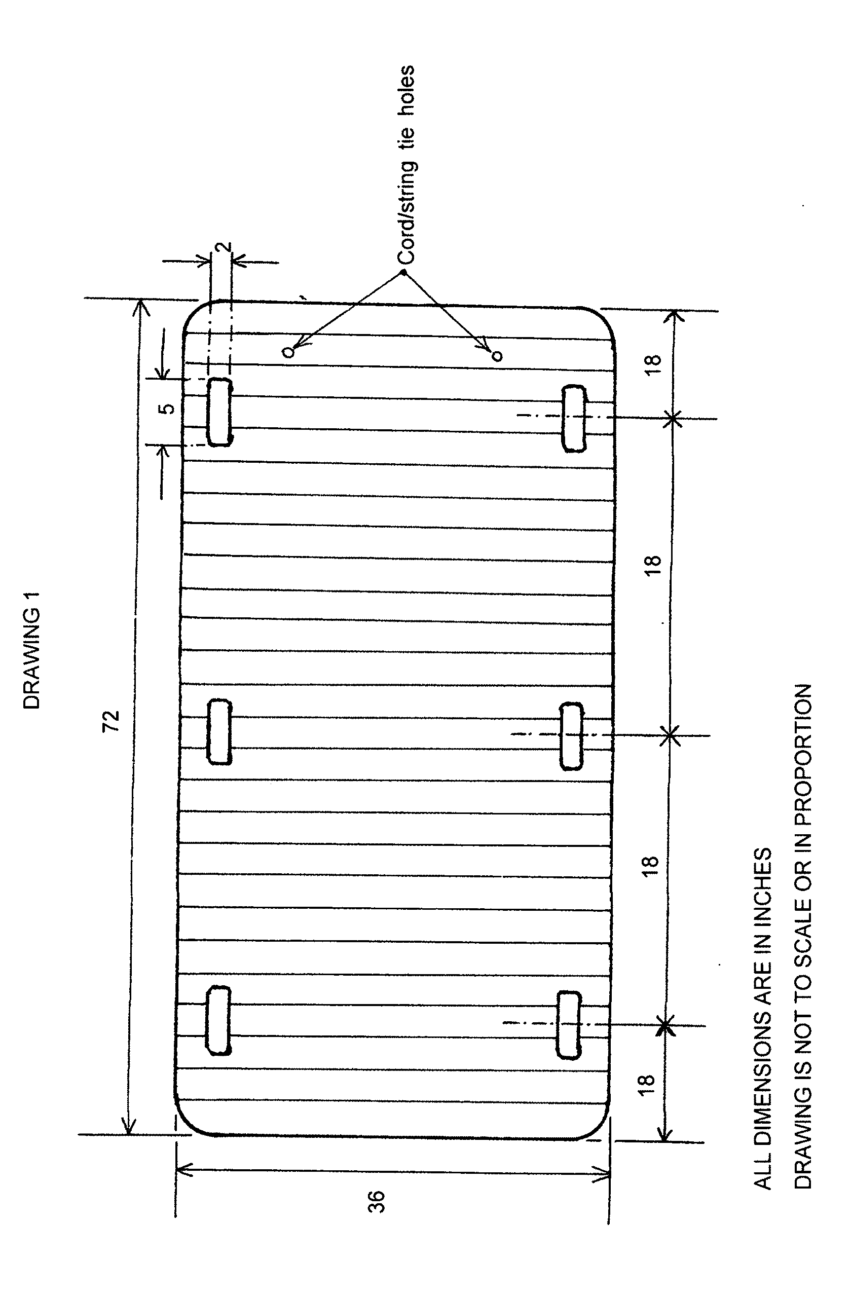
[0008] Drawing 1 (Page 1/5) is a front view of the BAGMASTER that provides a front view with dimensions, it also shows the lines along which the material the BAGMASTER is made from is creased to allow it to be rolled up for storage. The view also shows the holes that are used to insert cord/string, with references to the drawings showing its installation, to be used to tie it closed when rolled up for storage. All dimensions in this drawing are in inches and the drawing is not to scale or in proportion.
[0009] Drawing 2 (Page 2/5) is an isometric view of the BAGMASTER illustrating the corrugated nature of the material from which it is made. FIG. 3 provides detail of the channels in the materials corrugation. Also in this drawing there are references to Drawing 3 FIG. 1 and FIG. 2 which provide details of the curvature of the outer corners of the BAGMASTER and of the hand holds. All dimensions in this drawing are in inches and the drawing is not to scale or in proportion.
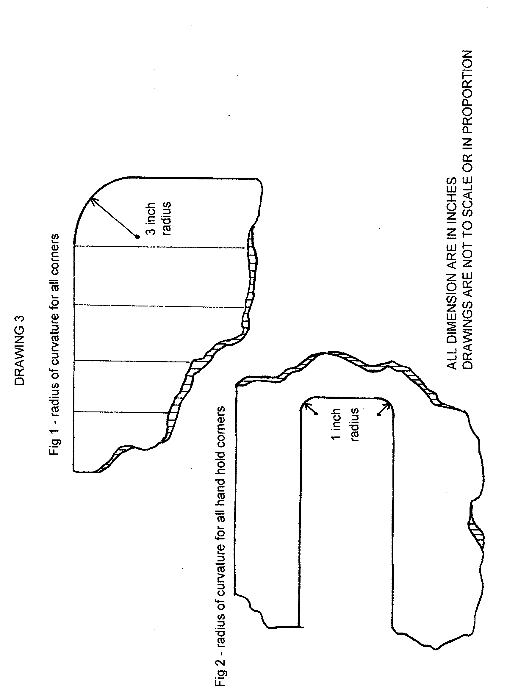
[0010] Drawing 3 (Page 3/5) comprises of FIG. 1 and FIG. 2 which show details of the curvature of the BAGMASTER outer corners (FIG. 1) and the hand holds (FIG. 2). FIG. 1 also has vertical lines showing the lines along which the material the BAGMASTER is made from is creased to allow it to be rolled up for storage. All dimensions in this drawing are in inches and the drawing is not to scale or in proportion.
[0011] Drawing 4 (Page 4/5) is a partial isometric view showing one corner and edge of the BAGMASTER giving details of where the tie holes are placed and the size of the tie holes. All dimensions in this drawing are in inches and the drawing is not to scale or in proportion.
[0012] Drawing 5 (Page 5/5) is a cross-section along Section A-A view of the tie hole with a cord/string inserted and tied in a knot on one side, both ties being installed and tied in the same manner with the knots on the same side of the corrugated plastic. All dimensions in this drawing are in inches and the drawing is not to scale or in proportion.
DETAIL DESCRIPTION OF CONSTRUCTION
[0013] 1. The BAGMASTER is constructed of corrugated plastic (Corriboard), COROPLAST or equal. (See: Drawing 2, FIG. 3) where the separation between the two sides is approximately 1/4 inch (See: Drawing 2 and Drawing 5) or as dictated by material supply (allowing for the manufacturing tolerances of the fabricator of the board).
[0014] 2. The BAGMASTER is designed to be symmetrical around its vertical and horizontal axis to simplify its use by avoiding a need to have it oriented in one direction when in service--it avoids a "this way up" preference when being used. (See: Drawing 1)
[0015] 3. All four corners of the BAGMASTER are rounded with a radius of 3 inches (or another suitable radius as decided in manufacture) to mitigate the problem "square" corners would present--snagging the plastic of the garbage bag and possibly ripping it when the BAGMASTER is being placed inside. (See: Drawing 1 and Drawing 3, FIG. 1)
[0016] 4. Handle hole openings are provided in the BAGMASTER to make moving a partially filled/filled garbage bag easier to pick up (to facilitate moving) Each corner of each handle hole has a radius of 1 inch (or another suitable radius as decided in manufacture) (See: Drawing 1 and Drawing 3, FIG. 2)
[0017] 5. The corrugated plastic material used in the fabrication of the BAGMASTER is creased every 3. 1/2 inches (or another suitable dimension as decided in manufacture) along the lines of the materials internal corrugation channels to facilitate the BAGMASTER being fold-rolled up (See Drawing 1 and Drawing 3, FIG. 1).
[0018] 6. Clips, Bulldog or similar, are provided to secure the garbage bag to the BAGMASTER (not shown in drawings)
[0019] 7. The BAGMASTER can be rolled up for storage, two "ties" using cord/string or equal are provided to keep the rolled up unit rolled up. To this end two holes are punched in suitable locations (See Drawing 4, FIG. 4) along one of the vertical (36 inch) edges of the BAGMASTER that will allow string/cord or equal be inserted, looped and tied (See Drawing 5, FIG. 5) as shown in Detail A-A
* * * * *
D00000
D00001
D00002
D00003
D00004
D00005
D00006
XML
uspto.report is an independent third-party trademark research tool that is not affiliated, endorsed, or sponsored by the United States Patent and Trademark Office (USPTO) or any other governmental organization. The information provided by uspto.report is based on publicly available data at the time of writing and is intended for informational purposes only.
While we strive to provide accurate and up-to-date information, we do not guarantee the accuracy, completeness, reliability, or suitability of the information displayed on this site. The use of this site is at your own risk. Any reliance you place on such information is therefore strictly at your own risk.
All official trademark data, including owner information, should be verified by visiting the official USPTO website at www.uspto.gov. This site is not intended to replace professional legal advice and should not be used as a substitute for consulting with a legal professional who is knowledgeable about trademark law.