Cold Pack Assembly
Conti; Brian Vincent
U.S. patent application number 16/032275 was filed with the patent office on 2019-01-17 for cold pack assembly. The applicant listed for this patent is CONTI-BROS, INC.. Invention is credited to Brian Vincent Conti.
| Application Number | 20190016514 16/032275 |
| Document ID | / |
| Family ID | 65000607 |
| Filed Date | 2019-01-17 |


| United States Patent Application | 20190016514 |
| Kind Code | A1 |
| Conti; Brian Vincent | January 17, 2019 |
COLD PACK ASSEMBLY
Abstract
An example cold pack assembly may include a pack and a band. The pack may include an internal cavity with a substance disposed within the internal cavity. The pack may also include a first recessed surface and a second recessed surface. The band may be disposed around the pack such that the band engages a first item and generates a first force to urge the first item into pressed engagement with the first recessed surface and the band engages a second item and generates a second force to urge the second item into pressed engagement with the second recessed surface. The band may be elastic.
| Inventors: | Conti; Brian Vincent; (Matthews, NC) | ||||||||||
| Applicant: |
|
||||||||||
|---|---|---|---|---|---|---|---|---|---|---|---|
| Family ID: | 65000607 | ||||||||||
| Appl. No.: | 16/032275 | ||||||||||
| Filed: | July 11, 2018 |
Related U.S. Patent Documents
| Application Number | Filing Date | Patent Number | ||
|---|---|---|---|---|
| 62531026 | Jul 11, 2017 | |||
| Current U.S. Class: | 1/1 |
| Current CPC Class: | B65D 71/50 20130101; B65D 63/109 20130101; F25D 3/08 20130101; F25D 2303/0843 20130101; F25D 2303/0841 20130101 |
| International Class: | B65D 71/50 20060101 B65D071/50; B65D 63/10 20060101 B65D063/10 |
Claims
1. An apparatus comprising: a pack comprising: an internal cavity, wherein a substance is disposed in the cavity; a first recessed surface and a second recessed surface, the first recessed surface being disposed on a first engagement side of the pack and the second recessed surface being disposed on a second engagement side of the pack, the first engagement side of the pack being disposed opposite the second engagement side of the pack; and a band disposed around the pack such that the band engages a first item and generates a first force to urge the first item into pressed engagement with the first recessed surface and the band engages a second item and generates a second force to urge the second item into pressed engagement with the second recessed surface, wherein the band is elastic.
2. The apparatus of claim 1, wherein the pack further comprises a first cutout disposed on a front side of the pack, wherein the band is disposed in the first cutout and the first cutout is configured to maintain the band in a vertical position relative to the pack.
3. The apparatus of claim 1, wherein the first cutout includes an upper lip and a lower lip, and wherein a portion of the band is disposed behind the upper lip and the lower lip to maintain the band within the first cutout.
4. The apparatus of claim 2, wherein the pack further comprises a second cutout disposed on a back side of the pack, the back side of the pack being disposed opposite the front side of the pack, the band being disposed in the second cutout.
5. The apparatus of claim 1, wherein the pack further comprises a protrusion; wherein the band further comprises an opening, and wherein the opening of the band is disposed on the protrusion.
6. The apparatus of claim 1, wherein the band further comprises raised features on an interior surface of the band that engages with the first or second item.
7. The apparatus of claim 1, wherein the first recessed surface is shaped as an arc.
8. The apparatus of claim 1, wherein the first recessed surface is shaped as an arc, wherein the arc is a portion of a circle.
9. The apparatus of claim 1, wherein the first recessed surface is shaped as an arc, wherein the arc is a portion of a circle having a radius, and wherein the first item includes a cylindrical portion having a radius that is substantially the same as the radius of the first recessed surface such that the first force applied by the band causes the first item to contact the first recessed surface along the arc.
10. An apparatus comprising: a pack comprising: an internal cavity, wherein a substance is disposed in the cavity; a first recessed surface and a second recessed surface; and a band disposed around the pack such that the band engages a first item and generates a first force to urge the first item into pressed engagement with the first recessed surface and the band engages a second item and generates a second force to urge the second item into pressed engagement with the second recessed surface, wherein the band is elastic.
11. The apparatus of claim 10, wherein the pack further comprises a first cutout, wherein the band is disposed in the first cutout and the first cutout is configured to maintain the band in a vertical position relative to the pack.
12. The apparatus of claim 10, wherein the first cutout includes an upper lip and a lower lip, and wherein a portion of the band is disposed behind the upper lip and the lower lip to maintain the band within the first cutout.
13. The apparatus of claim 11, wherein the pack further comprises a second cutout, the band being disposed in the second cutout.
14. The apparatus of claim 10, wherein the pack further comprises a protrusion; wherein the band further comprises an opening, and wherein the opening of the band is disposed on the protrusion.
15. The apparatus of claim 10, wherein the band further comprises raised features on an interior surface of the band that engage with the first or second item.
16. The apparatus of claim 1, wherein the first recessed surface is shaped as an arc.
17. The apparatus of claim 1, wherein the first recessed surface is shaped as an arc, wherein the arc is a portion of a circle.
18. The apparatus of claim 1, wherein the first recessed surface is shaped as an arc, wherein the arc is a portion of a circle having a radius, and wherein the first item includes a cylindrical portion having a radius that is substantially the same as the radius of the first recessed surface such that the first force applied by the band causes the first item to contact the first recessed surface along the arc.
Description
CROSS REFERENCE TO RELATED APPLICATIONS
[0001] This application claims the benefit of U.S. Provisional Application No. 62/531,026 filed on Jul. 11, 2017, the entire contents of which are incorporated herein by reference.
TECHNICAL FIELD
[0002] Example embodiments generally relate to refrigeration technology, and more particularly, relate to a apparatuses for passive temperature maintenance.
BACKGROUND
[0003] Powered refrigeration can maintain beverages and other temperature-sensitive goods at desired temperatures. In the absence of powered refrigeration, insulated coolers filled with melting ice is the typical solution for maintaining goods at desired temperatures as long as possible.
SUMMARY OF SOME EXAMPLES
[0004] An example cold pack assembly is provided that may include a pack and a band. An example cold pack assembly may include a pack and a band. The pack may include an internal cavity with a substance disposed within the internal cavity. The pack may also include a first recessed surface and a second recessed surface. The band may be disposed around the pack such that the band engages a first item and generates a first force to urge the first item into pressed engagement with the first recessed surface and the band engages a second item and generates a second force to urge the second item into pressed engagement with the second recessed surface. The band may be elastic.
[0005] Another example cold pack assembly may include a pack and a band. The pack may comprise an internal cavity and a substance may be disposed in the internal cavity. The pack may further comprise a first recessed surface and a second recessed surface. The first recessed surface may be disposed on a first engagement side of the pack and the second recessed surface may be disposed on a second engagement side of the pack. The first engagement side of the pack may be disposed opposite the second engagement side of the pack. The band may be disposed around the pack such that the band engages a first item and generates a first force to urge the first item into pressed engagement with the first recessed surface and the band engages a second item and generates a second force to urge the second item into pressed engagement with the second recessed surface. The band may be elastic.
BRIEF DESCRIPTION OF THE DRAWINGS
[0006] Having thus described some example cold pack assemblies in general terms, reference will now be made to the accompanying drawings, which are not necessarily drawn to scale, and wherein:
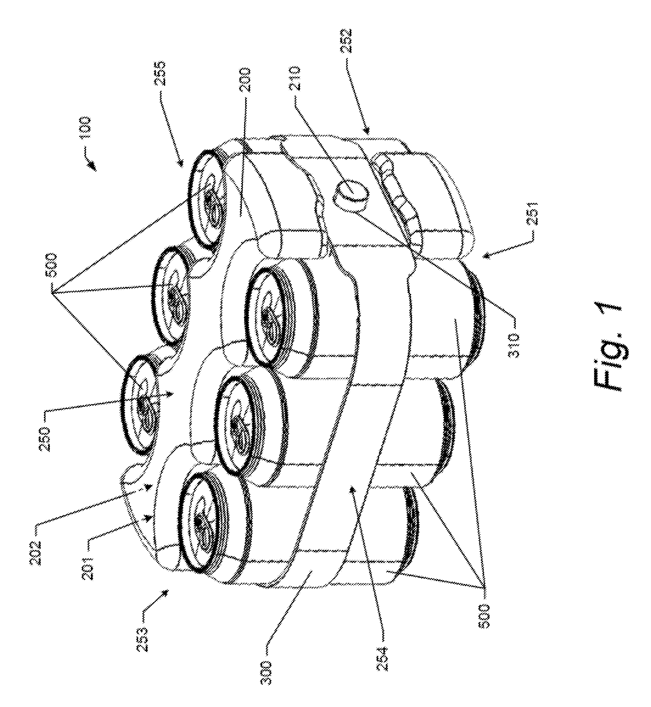
[0007] FIG. 1 shows a perspective view of an example cold pack assembly securing cans in accordance with an example embodiment;
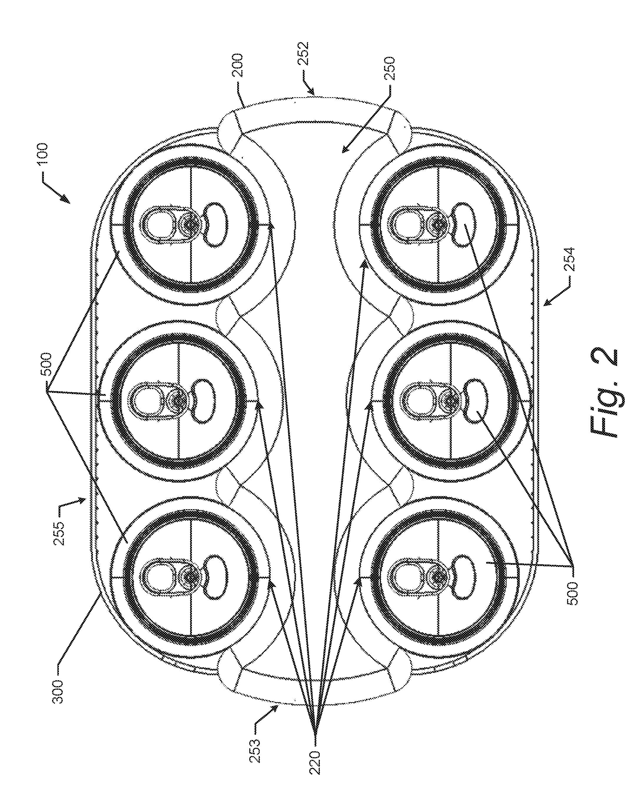
[0008] FIG. 2 shows top view of an example cold pack assembly securing cans in accordance with an example embodiment;
[0009] FIG. 3 shows a top view of a portion of an example pack securing a can in accordance with an example embodiment;
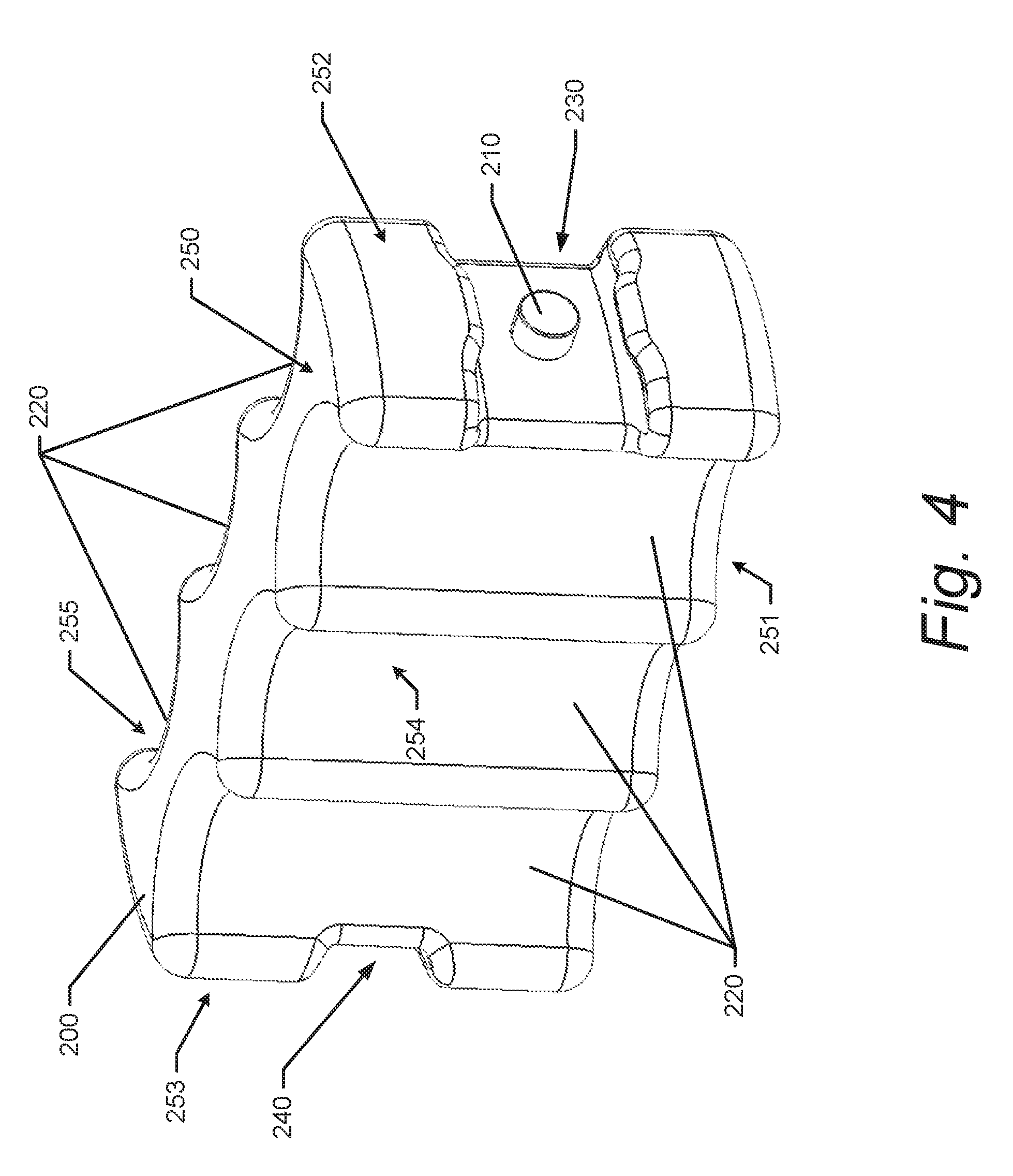
[0010] FIG. 4 shows a perspective view of an example pack in accordance with an example embodiment;
[0011] FIG. 5 shows an top view of a recessed surface of an example pack and the associated geometry in accordance with an example embodiment;
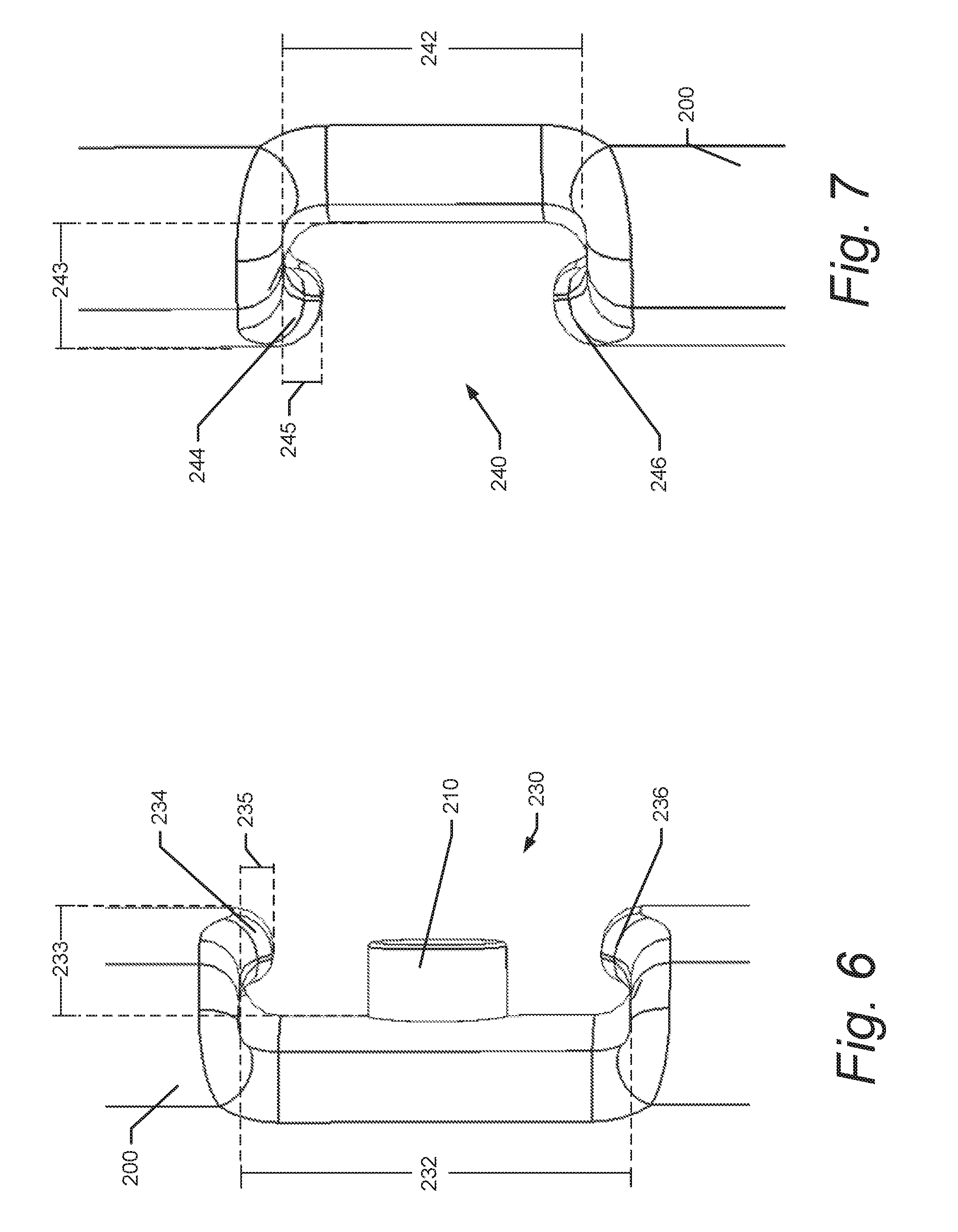
[0012] FIG. 6 shows an example band engagement cutout in accordance with an example embodiment;
[0013] FIG. 7 shows another example band engagement cutout in accordance with an example embodiment;
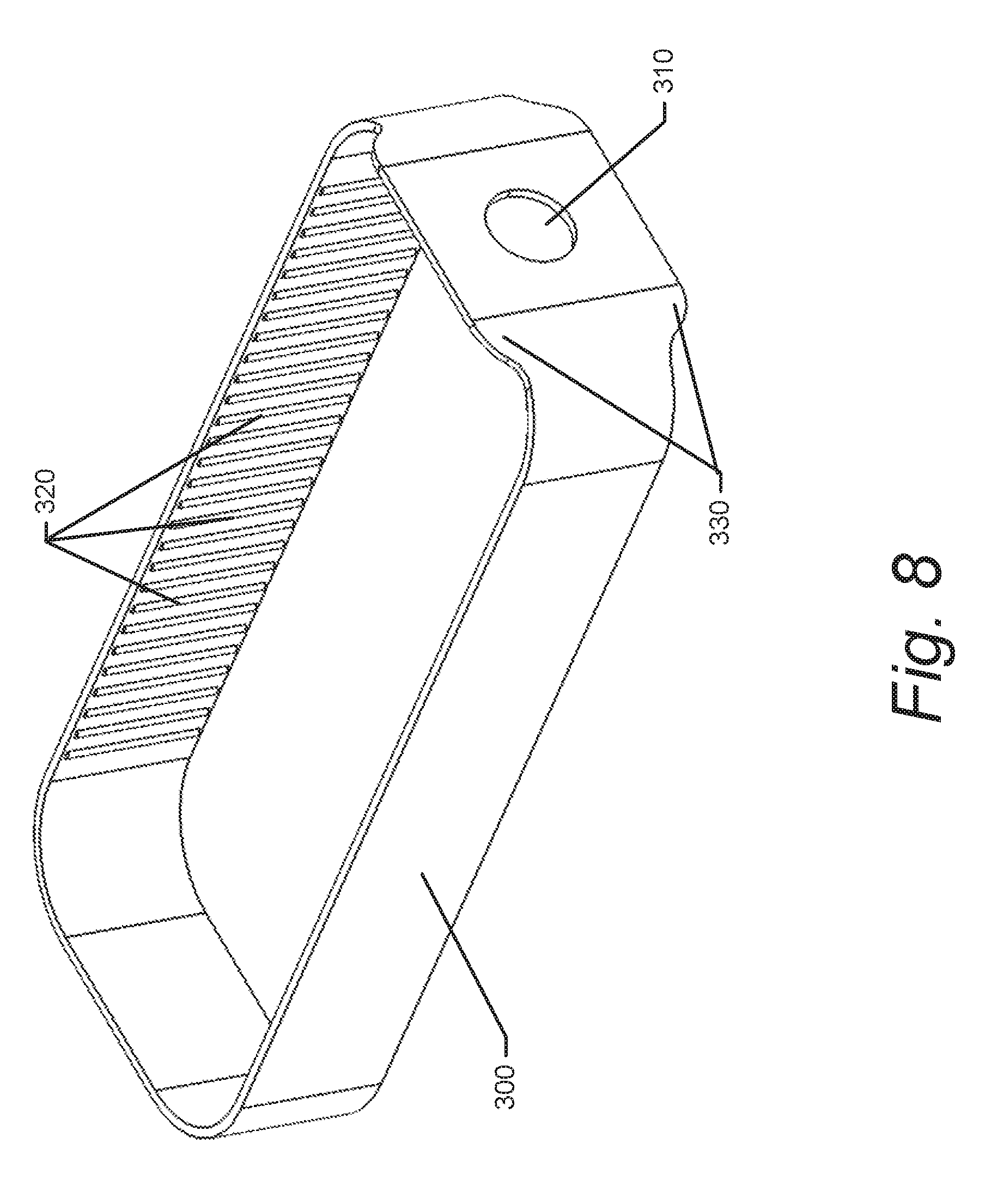
[0014] FIG. 8 shows an example band in accordance with an example embodiment;
[0015] FIG. 9 shows a perspective view of an example cold pack assembly in accordance with an example embodiment; and
[0016] FIG. 10 shows a side view of an example cold pack assembly in accordance with an example embodiment.
DETAILED DESCRIPTION OF SOME EXAMPLE EMBODIMENTS
[0017] Some example embodiments now will be described more fully hereinafter with reference to the accompanying drawings, in which some, but not all example embodiments are shown. Indeed, the examples described and pictured herein should not be construed as being limiting as to the scope, applicability or configuration of the present disclosure. Rather, these example embodiments are provided so that this disclosure will satisfy applicable legal requirements. Like reference numerals refer to like elements throughout. As used herein, operable coupling should be understood to relate to direct or indirect connection that, in either case, enables functional interconnection of components that are operably coupled to each other.
[0018] According to some example embodiments, an example cold pack assembly is provided. According to some example embodiments, an example cold pack assembly may include a pack and a band. The pack may include an internal sealed cavity with a substance disposed in the cavity. The substance may exhibit thermal properties. The pack may also include at least a first recessed surface and a second recessed surface. The first recessed surface may be disposed on a first side of the pack and the second recessed surface may be disposed on a second side of the pack. The first side of the pack may be opposite the second side of the pack. The pack may further include a cutout disposed on a third side of the pack. The band may be disposed around the pack such that the band engages a first item to urge the first item into pressed engagement with the first recess and the band engages a second item to urge the second item into pressed engagement with the second recess. The band may also be disposed in the within the cutout on the third side of the pack.
[0019] FIG. 1 shows a perspective view of an example cold pack assembly 100 securing cans 500 in accordance with an example embodiment. The cold pack assembly 100 may include a pack 200 and a band 300. As shown in FIG. 1, the band 300 may wrap around the pack 200 in, for example, a substantially horizontal direction to secure the cans 500 to the pack 200. The pack may have a top 250, a bottom 251, a front side 252, a back side 253, a first engagement side 254, and a second engagement side 255. Note that the surfaces of the pack 200 are merely provided for ease of explanation regarding spatial references. As such, the band 300 may wrap around the front side 252, the first engagement side 254, the back side 253, and the second engagement side 255 of the pack 200. While the example embodiment herein is shown with cans 500, it is understood that any type of product or good that may need to be kept cold may be used in conjunction with the cold pack assembly 100--the cans 500 being just one example. The pack 200 may be a sealed or closed surface (e.g., plastic) container with an internal cavity 201. According to some example embodiments, the pack 200 may include a removable cap. The internal cavity 201 may have a substance 202 disposed therein. The substance 202 may be a refrigerant gel or liquid. The substance 202 may have properties that cause the substance 202 to maintain a temperature for relatively long periods of time including when there is a difference between the ambient temperature and the temperature of the substance 202. In this regard, the substance 202 may, after being subjected to a cold temperature for a sufficient duration of time, remain cold for relatively long periods of time after being removed from the cold environment and introduced into a warmer environment. In some example embodiments, the substance 202 may be water, hyroxyethyl cellulose, sodium polyacrylate, or vinyl-coated silica gel.
[0020] The pack 200 may have recessed surfaces 220 (see FIGS. 2 and 3), on opposite sides (i.e., first side 254 and second side 255). The recessed surfaces 220 may be concave in shape and may be designed to contour into the shape of a standard can or bottle to maximize surface contact and thermal transfer between the items loaded into the cold pack assembly 100. In this regard, the recessed surfaces 220 may have a profile of that is a portion of a circle or otherwise be arcuate, where, for example, an arc of the recessed surfaces 220 has a length that is less than the circumference of a semi-circle having the same radius. According to some example embodiments, the recessed surfaces 220 may be scalloped in shape.
[0021] The band 300 may be elastic and wrapped around the pack 200. The band 300 may be sized such that, at rest, the band 300 is shorter than the length around the cans 500 and the pack 200. As such, due to elastic tension supplied by the band 300 being stretched and the length being expanded, the band 300 may tend to urge the cans 500 into the recessed surfaces 220 to maximize surface contact and thermal transfer. According to some example embodiments, the band 300 may have an opening 310 that may be seated on a protrusion 210 of the pack 200, which may assist in maintaining the position of the band 300 and prevent the band from shifting when, for example, a can is slid out the cold pack assembly 100 or when no cans are installed in the cold pack assembly 100.
[0022] FIG. 2 shows top view of the example cold pack assembly 100 securing cans 500 in accordance with an example embodiment. Here, according to some example embodiments, the engagement between recessed surfaces 220 of the pack 200 and the cans 500 can be seen, with the band 300 providing in a pressing force against the cans towards the recessed surfaces 220.
[0023] FIG. 3 shows a portion of the cold pack assembly 100 with a can 500. As shown in FIG. 3, the band 300 may be sized to apply a force 501 (indicated by the arrow) onto the can 500, which in turn applies a force that urges the can 500 against the contact surface 502 of the recessed surface 220 of either the first engaging side 254 or the second engaging side 255. This force 501 may operate to cause surface area contact (which may be shaped as a partial cylinder) between the can 500 and the recessed surface 220 to maximize thermal conduction between the surface of the can 500 and the recessed surface 220.
[0024] FIG. 4 shows a perspective view of the example pack 200 in accordance with an example embodiment. As described above, the pack 200 may include recessed surfaces 220 and a protrusion 210. The protrusion 210 may be disposed on the front side 252 or the back side 253. The pack 200 may also include a front side band engagement cutout 230 and a back side band engagement cutout 240. Note that the directional terms are merely provided for ease of explanation and are not limiting. According to some example embodiments, the pack 200 may have only one or no band engagement cutouts. The cutouts 230 and 240 may be configured to maintain the band 300 in a desired vertical position with respect to the pack 200. In this regard, the cutouts 230 and 240 may be configured to hold the band 300 in the desired vertical position even during installation of cans 500 which may tend to cause the band 300 to move vertically in the direction of the installation (e.g., downward when the cans 500 are being installed from the top).
[0025] FIG. 5 shows a portion of the pack 200, and in particular, an enlarged view of a recessed surface 220. It can be seen that, according to some example embodiments, the recessed surface 220 may have an arcuate shape as a portion of a circle 261. The circle 261 may have a center at 262 and may thus define the recessed surface 220 with respect to a radius 263. The perimeter of the circle 261 may have the same shape as a perimeter of an object to be engaged with the recessed surface 220 to maximize surface area contact between the recessed surface 220 and the object.
[0026] FIG. 6 shows the front side band engagement cutout 230 in accordance with an example embodiment. In this regard, the cutout 230 may be a recessed area on a front side of the pack 200 that is configured to receive a portion of the band 300. The cutout 230 may have a height 232 and a depth 233. Further, the cutout 230 may, according to some example embodiments, include an upper lip 234 and a lower lip 236 that extend into the cutout 230 to form, for example, a C-shaped cutout area. In this regard, the upper lip 234 may have a lip height 235. The lower lip 236 may have the same or a similar height. According to some example embodiments, however, the cutout 230 may only have a single lip or no lips (e.g., making the cutout area a U-shape). The cutout 230 and the lips 235, 236, may operate to hold the band 300 in position on the pack 200.
[0027] FIG. 7 shows the back side band engagement cutout 240 in accordance with an example embodiment. In this regard, the cutout 240 may be a recessed area on the back side of the pack 200 that is configured to receive a portion of the band 300. The cutout 240 may have a height 242 and a depth 243. Further, the cutout 240 may, according to some example embodiments, include an upper lip 244 and a lower lip 246 that extend into the cutout 240 to form, for example, a C-shaped cutout area. In this regard, the upper lip 244 may have a lip height 245. The lower lip 246 may have the same or a similar height. According to some example embodiments, however, the cutout 240 may only have a single lip or no lips (e.g., making the cutout area a U-shape). The cutout 240 and the lips 245, 246, may operate to hold the band 300 in position on the pack 200.
[0028] FIG. 8 shows the example band 300 in accordance with an example embodiment. As mentioned above, the band 300 may be an elastic band. As shown in FIG. 8, the band 300 may include raised features 320 (e.g., bars, elongated domes, or the like) disposed on an internal surface of the band 300. The raised features 320 may, according to some example embodiments, be disposed on the band 300 at positions where the band 300 may engage with an item to loaded in the cold pack assembly 100. The raised features 320 may operate to decrease friction between the loaded item and the band 300 to allow for easier removal of the loaded item by sliding the item in along a length of the raised features 320. Also, as mentioned above, the band 300 may include an opening 310 that may be configured to engage with a protrusion of the pack 200 to secure the band 300 to the pack 200. As shown in FIG. 8, opening 310 may be circular, but according to some example embodiments the opening 310 may be any type of hole in the band 300, such as a slit. According to some example embodiments, the band 300 may have a plurality of openings along the band 300's length. According to some example embodiments, the band 300 may be a strip (rather than a loop) where the ends of the band 300 have openings for affixing the band 300 to a protrusion of the pack 200. In this regard, the band 300, in the form of a strip, may be adjustable by selecting one of a plurality of openings in the band 300 for engagement with a protrusion (e.g., protrusion 210) on the pack 200.
[0029] Further, in some example embodiments, the band 300 may be uniform in height. However, according to some example embodiments, as shown in FIG. 8, the band 300 may increase in height at region 330 surrounding an opening 310. The increased amount of material around the openings may operate to strengthen the band 300 in those locations to prevent tearing.
[0030] FIG. 9 shows a perspective view of the example cold pack assembly 100 in accordance with an example embodiment. As shown in FIG. 9, no items are loaded into the cold pack assembly 100. The band 300 may be wrapped around the pack 200 and the opening 310 in the band 300 may be engaged with the protrusion 210 of the pack 200.
[0031] FIG. 10 shows a view of the first engaging side 254 of the example cold pack assembly 100 in accordance with an example embodiment. Cutouts 230, 240 may be disposed at the front side 252 and the back side 253 of the pack 200 for engagement with the band 300 as described above. Additionally, pack 200 may include protruding feet 290 on a bottom side of the pack 200.
[0032] Having described some example embodiments of cold pack assemblies above, some additional example embodiments are now described that are related to or based on various features and combinations of features described above. In this regard, an example cold pack assembly is provided that may include a pack and a band. An example cold pack assembly may include a pack and a band. The pack may include an internal cavity with a substance disposed within the internal cavity. The pack may also include a first recessed surface and a second recessed surface. The band may be disposed around the pack such that the band engages a first item and generates a first force to urge the first item into pressed engagement with the first recessed surface and the band engages a second item and generates a second force to urge the second item into pressed engagement with the second recessed surface. The band may be elastic.
[0033] Another example cold pack assembly may include a pack and a band. The pack may comprise an internal cavity and a substance may be disposed in the internal cavity. The pack may further comprise a first recessed surface and a second recessed surface. The first recessed surface may be disposed on a first engagement side of the pack and the second recessed surface may be disposed on a second engagement side of the pack. The first engagement side of the pack may be disposed opposite the second engagement side of the pack. The band may be disposed around the pack such that the band engages a first item and generates a first force to urge the first item into pressed engagement with the first recessed surface and the band engages a second item and generates a second force to urge the second item into pressed engagement with the second recessed surface. The band may be elastic.
[0034] Additionally, according to some example embodiments, the pack may further comprise a first cutout disposed on a front side of the pack. The band may be disposed in the first cutout and the first cutout may be configured to maintain the band in a vertical position relative to the pack. Additionally or alternatively, the first cutout may include an upper lip and a lower lip. Further, a portion of the band may be disposed behind the upper lip and the lower lip to maintain the band within the first cutout. Additionally or alternatively, the pack may further comprise a second cutout, for example, disposed on a back side of the pack. The second cutout may include an upper lip and a lower lip. Further, a portion of the band may be disposed behind the upper lip and the lower lip to maintain the band within the first cutout. The back side of the pack may, according to some example embodiments, be disposed opposite the front side of the pack. Additionally or alternatively, the pack may further comprise a protrusion. The band may further comprise an opening. The opening of the band may be disposed on the protrusion. Additionally or alternatively, the band may further comprise raised features on an interior surface of the band that engage with the first or second item and operate to reduce the friction with the first or second item (i.e., reduce the surface area of engagement between the first or second item and the band) during removal of the same from the cold pack assembly. Additionally or alternatively, the first or second recessed surface may be shaped as an arc. According to some example embodiments, the arc may take the shape of a portion of a circle. Further, because the recessed surfaces have a height, the recessed surfaces, in three dimensions, may take the shape of a partial cylinder where the arc is a cross-section. Additionally or alternatively, the first or second recessed surface is shaped as an arc, wherein the arc is a portion of a circle having a radius. The first item may include a cylindrical portion (e.g., central portion of the can 500) having a radius that is substantially the same as the radius of the first recessed surface such that the first force applied by the band causes the first item to contact the first recessed surface along the arc. The second item may include a cylindrical portion (e.g., central portion of the can 500) having a radius that is substantially the same as the radius of the second recessed surface such that the second force applied by the band causes the second item to contact the second recessed surface along the arc.
[0035] Many modifications and other embodiments according to those set forth herein will come to mind to one skilled in the art to which these embodiments pertain having the benefit of the teachings presented in the foregoing descriptions and the associated drawings. Therefore, it is to be understood that embodiments are not to be limited to the specific ones disclosed and that modifications and other embodiments are intended to be included within the scope of the appended claims. Moreover, although the foregoing descriptions and the associated drawings describe exemplary embodiments in the context of certain exemplary combinations of elements and/or functions, it should be appreciated that different combinations of elements and/or functions may be provided by alternative embodiments without departing from the scope of the appended claims. In this regard, for example, different combinations of elements and/or functions than those explicitly described above are also contemplated as may be set forth in some of the appended claims. In cases where advantages, benefits or solutions to problems are described herein, it should be appreciated that such advantages, benefits and/or solutions may be applicable to some example embodiments, but not necessarily all example embodiments. Thus, any advantages, benefits or solutions described herein should not be thought of as being critical, required or essential to all embodiments or to that which is claimed herein. Although specific terms are employed herein, they are used in a generic and descriptive sense only and not for purposes of limitation.
* * * * *
D00000
D00001
D00002
D00003
D00004
D00005
D00006
D00007
D00008
D00009
XML
uspto.report is an independent third-party trademark research tool that is not affiliated, endorsed, or sponsored by the United States Patent and Trademark Office (USPTO) or any other governmental organization. The information provided by uspto.report is based on publicly available data at the time of writing and is intended for informational purposes only.
While we strive to provide accurate and up-to-date information, we do not guarantee the accuracy, completeness, reliability, or suitability of the information displayed on this site. The use of this site is at your own risk. Any reliance you place on such information is therefore strictly at your own risk.
All official trademark data, including owner information, should be verified by visiting the official USPTO website at www.uspto.gov. This site is not intended to replace professional legal advice and should not be used as a substitute for consulting with a legal professional who is knowledgeable about trademark law.