Systems And Methods For Securement Of Cargo On A Pallet
Millhouse; Andrew ; et al.
U.S. patent application number 16/034667 was filed with the patent office on 2019-01-17 for systems and methods for securement of cargo on a pallet. The applicant listed for this patent is Walmart Apollo, LLC. Invention is credited to Timothy J. Burleson, Andrew Millhouse, Jacob R. Schrader.
| Application Number | 20190016502 16/034667 |
| Document ID | / |
| Family ID | 65000600 |
| Filed Date | 2019-01-17 |


| United States Patent Application | 20190016502 |
| Kind Code | A1 |
| Millhouse; Andrew ; et al. | January 17, 2019 |
SYSTEMS AND METHODS FOR SECUREMENT OF CARGO ON A PALLET
Abstract
Methods and systems are provided for securing cargo on a pallet using a series of interconnected inflatable members. The system is secured to the pallet using securement straps connected to a fastener. The system prevents cargo from damage or loss as a result of falls from the pallet or collisions with other objects in the environment. Walls of the system can be gradually raised or lowered as cargo is added or removed to provide access to the highest cargo in a stack while protecting the cargo in a lower part of the stack. In some embodiments, the inflatable members can be filled with heated or cooled liquids to improve environmental storage conditions of cargo on the pallet.
| Inventors: | Millhouse; Andrew; (Gilbert, AZ) ; Schrader; Jacob R.; (Sterling, IL) ; Burleson; Timothy J.; (Bentonville, AR) | ||||||||||
| Applicant: |
|
||||||||||
|---|---|---|---|---|---|---|---|---|---|---|---|
| Family ID: | 65000600 | ||||||||||
| Appl. No.: | 16/034667 | ||||||||||
| Filed: | July 13, 2018 |
Related U.S. Patent Documents
| Application Number | Filing Date | Patent Number | ||
|---|---|---|---|---|
| 62532559 | Jul 14, 2017 | |||
| Current U.S. Class: | 1/1 |
| Current CPC Class: | B65D 19/06 20130101; B65D 81/03 20130101; B65D 2519/00044 20130101; B65D 2519/00099 20130101; B65D 2519/00587 20130101; B65D 2519/00875 20130101; B65D 2519/00034 20130101; B65D 2519/0081 20130101; B65D 19/38 20130101; B65D 2519/00064 20130101; B65D 2519/00661 20130101; B65D 2519/00527 20130101; B65D 71/0096 20130101; B65D 2519/00029 20130101; B65D 2519/00174 20130101; B65D 2519/00273 20130101; B65D 21/08 20130101 |
| International Class: | B65D 19/38 20060101 B65D019/38 |
Claims
1. An inflatable system for securing cargo on a pallet, comprising: a plurality of inflatable members configured to operatively couple to and extend about a perimeter of a pallet, the plurality of inflatable members configured to have an inflated state in which the plurality of inflatable members form a wall extending vertically from the perimeter of the pallet to surround cargo on the pallet and a deflated state in which the plurality of inflatable members are collapsed to provide lateral access to the cargo on the pallet, the plurality of inflatable members arranged in a stack having a vertical configuration and being fluidically connected by inlet passages and outlet passages; an inlet port located on a lowest one of the plurality of inflatable members in the stack; a pressure regulator located in each of the inlet passages, the pressure regulator preventing fluid from passing from lower to higher inflatable members in the stack through the inlet passage until a threshold pressure is reached in the lower inflatable member; at least one check valve located in each outlet passage to facilitate ordered draining of fluid from the inflatable members; and a securement strap attached to a fastener and at least one of the plurality of inflatable members to selectively secure the plurality of inflatable members to the pallet, wherein inflation of the lowest inflatable member creates tension to secure the fastener to the pallet.
2. The system of claim 1, wherein the plurality of inflatable members in the stack are consecutively inflated in order from lowest to highest via the inlet port and the inlet passages.
3. The system of claim 1, wherein the plurality of inflatable members in the stack are consecutively deflated in order from highest to lowest via a side port of each check valve.
4. The system of claim 1, further comprising a reinforcing wire ring at each intersection between inflatable members, the reinforcing wire ring providing lateral rigidity to the plurality of inflatable members, wherein a shape of a perimeter of the plurality of inflatable members conforms to a shape of the reinforcing wire ring.
5. The system of claim 1, further comprising a base that is laid over a cargo supporting surface of the pallet and is attached to the lowest inflatable member.
6. The system of claim 1, wherein the fastener is a hook or steel cleat configured to latch on to the pallet as the lowest one of the plurality of inflatable members is inflated.
7. The system of claim 1, wherein the securement strap secures under a cargo supporting surface of the pallet.
8. The system of claim 1, wherein the fluid is air.
9. The system of claim 1, wherein the fluid is a chilled or heated liquid.
10. The system of claim 1, further comprising a vacuum source attachable to the inlet port to remove the fluid.
11. The system of claim 1, wherein the inflatable members comprise rubber, silicone, or plastic.
12. A method for securing cargo on a pallet, comprising: inflating a plurality of inflatable members to extend vertically from a pallet to surround cargo on the pallet, the inflatable members arranged in a stack having a vertical configuration and being fluidically connected by inlet passages and outlet passages, at least one check valve located in each outlet passage to facilitate draining of fluid from the inflatable members; and securing the plurality of inflatable member to the pallet via a securement strap attached to a fastener and at least one of the inflatable members by inflating a lowest one of the plurality of inflatable member to create tension and selectively secure the fastener to the pallet, wherein inflating the plurality of inflatable members includes introducing fluid into the lowest one of the plurality of inflatable members through an inlet port, the lowest one of the plurality of inflatable members being fluidically isolated from a next higher one of the plurality of inflatable members in the stack by a pressure regulator located in a first one of the inlet passages configured to fluidically connect the lowest one of the plurality of inflatable members to the next higher one of the plurality of inflatable members until a threshold pressure is reached in the lower inflatable member.
13. The method of claim 12, wherein inflating the plurality of inflatable members in the stack proceeds consecutively in order from lowest to highest via the inlet port and the inlet passages.
14. The method of claim 12, further comprising deflating the plurality of inflatable members in the stack consecutively in order from highest to lowest via a side port of each check valve.
15. The method of claim 12, further comprising providing a reinforcing wire ring at each intersection between inflatable members, the reinforcing wire ring providing lateral rigidity to the plurality of inflatable members, wherein a shape of a perimeter of the plurality of inflatable members conforms to a shape of the reinforcing wire ring.
16. The method of claim 12, wherein the lowest inflatable member is attached to a base that is laid over a cargo supporting surface of the pallet.
17. The method of claim 12, wherein the fastener is a hook or steel cleat configured to latch on to the pallet as the lowest one of the plurality of inflatable members is inflated.
18. The method of claim 12, wherein the securement strap secures under a cargo supporting surface of the pallet.
19. The method of claim 12, wherein the fluid is air.
20. The method of claim 12, wherein the fluid is a chilled or heated liquid.
21. The method of claim 12, further comprising attaching a vacuum source to each check valve to remove the fluid.
22. The method of claim 12, wherein the inflatable members comprise rubber, silicone, or plastic.
Description
RELATED APPLICATION
[0001] This application claims priority to U.S. Provisional Application No. 62/532,559, filed Jul. 14, 2017, the entire contents of which is incorporated herein by reference.
BACKGROUND
[0002] Cargo shipped on pallets is susceptible to damage or loss if secured improperly.
BRIEF DESCRIPTION OF DRAWINGS
[0003] Illustrative embodiments are shown by way of example in the accompanying drawings and should not be considered as a limitation of the present disclosure:
[0004] FIG. 1A illustrates a cutaway view of an inflatable system for securing cargo on a pallet according to various embodiments of the present disclosure.
[0005] FIG. 1B illustrates a magnified view of a portion of FIG. 1A.
[0006] FIG. 1C illustrates a magnified view of a portion of FIG. 1A.
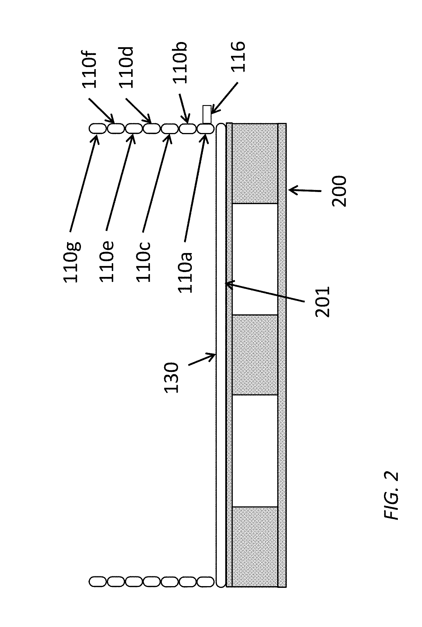
[0007] FIG. 2 illustrates the system of FIG. 1A in a deflated state in accordance with various embodiments described herein.
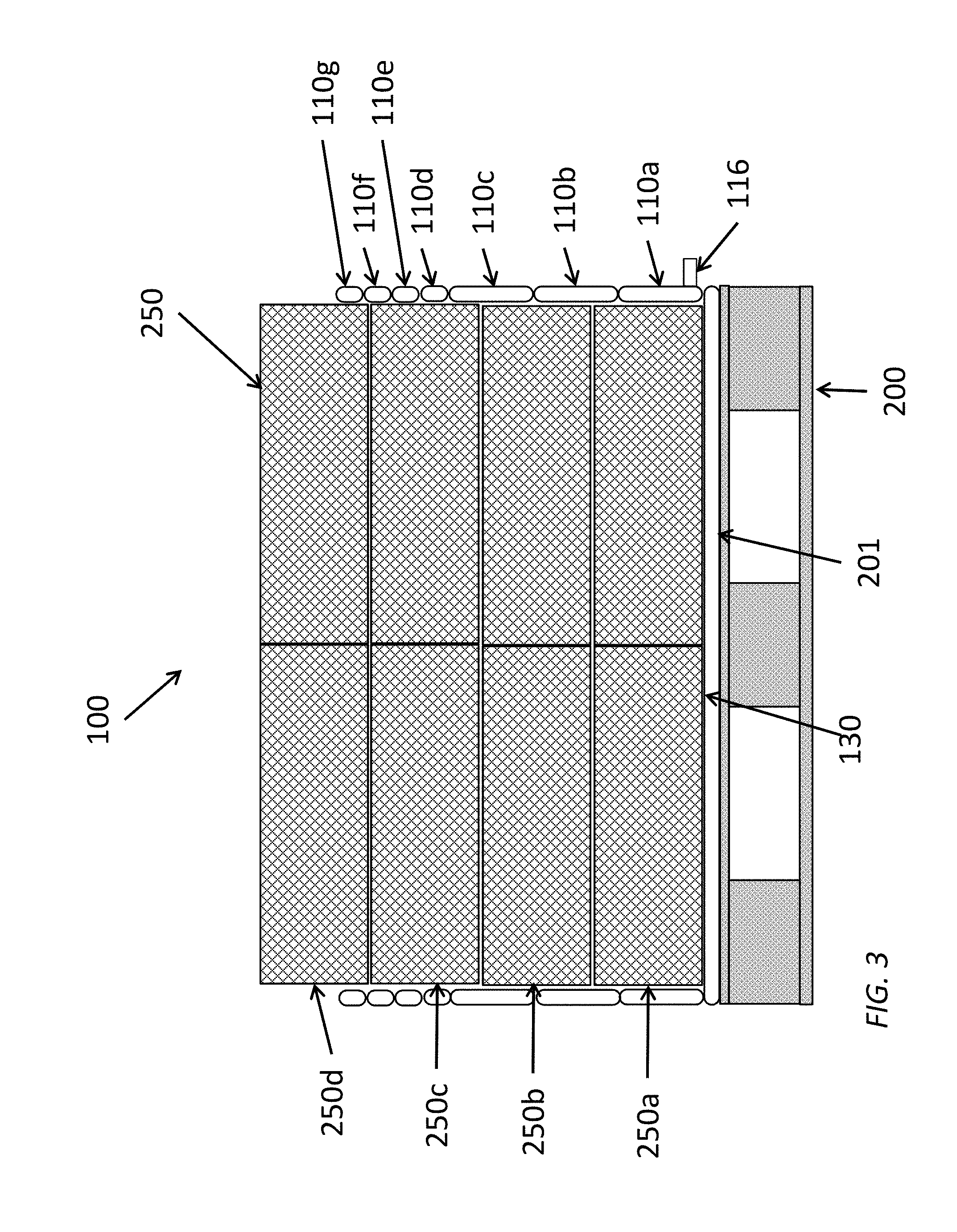
[0008] FIG. 3 illustrates the system of FIG. 1A in a partially inflated state in accordance with various embodiments described herein.
[0009] FIG. 4 illustrates a top-down view of the system for securing cargo on a pallet of FIGS. 1A-1C.
[0010] FIGS. 5A and 5B illustrate a front view and a side cutaway view, respectively, of a system for securing cargo on a pallet wherein an inflatable member is in a deflated state according to various embodiments of the present disclosure.
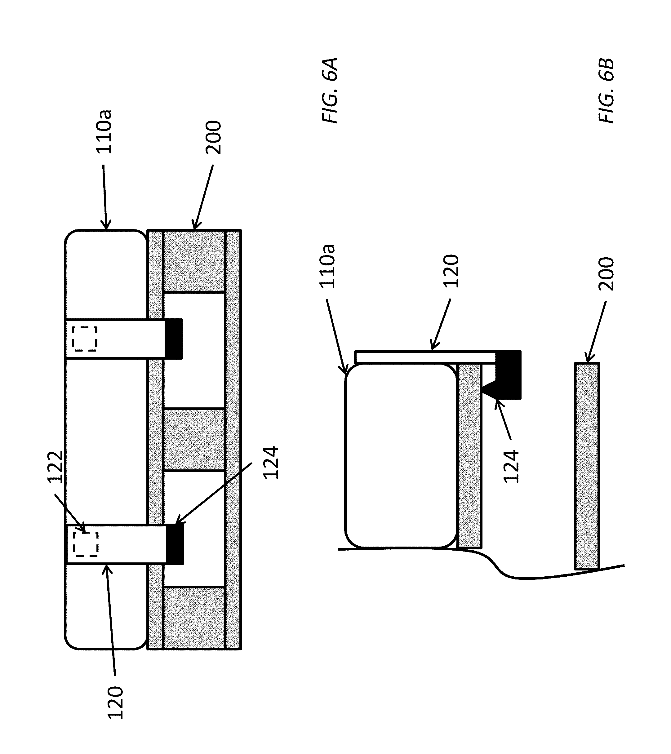
[0011] FIGS. 6A and 6B illustrate a front view and a side cutaway view, respectively, of the system of FIGS. 5A and 5B wherein the inflatable member is in an inflated state according to various embodiments of the present disclosure.
DETAILED DESCRIPTION
[0012] Described in detail herein are methods and systems for securing cargo on a pallet using a series of interconnected inflatable members. The system can be secured to a pallet using securement straps connected to a fastener. The system can prevent damage or loss of cargo as a result of falls from the pallet, shifting of objects on the pallet, or collisions with other objects in the environment. Walls of the system can be gradually inflated as cargo is added to secure cargo already added to the pallet as additional cargo is placed on top of the previously added cargo, and can be quickly deflated or gradually deflated to lower the wall as cargo is removed to provide access to the highest cargo in a stack while protecting the cargo in a lower part of the stack. In some embodiments, the inflatable members can be filled with heated or cooled liquids to improve environmental storage conditions of cargo on the pallet.
[0013] In conventional transport systems, cargo on pallets is secured and protected using blankets or shrink wrap. These solutions are often inadequate to physically protect the cargo from damage caused by collisions with other objects, shifting of objects on the pallet, or to protect the cargo from falling off the pallet during handling. Moreover, accessing the cargo requires removal of the blanket or breach of the wrap such that the remaining cargo is no longer protected. By surrounding the cargo with segmented inflated buffer members that can absorb or deflect collisions and retain cargo within the footprint of the pallet, exemplary embodiments of the systems and methods described herein advantageously provide improved security for cargo that overcomes problems associated with conventional systems and methods of securing cargo on pallets. Further, systems and methods described herein can be selectively lowered (continuously or intermittently) to allow lateral access to the top levels of cargo (for example, for removal of items) while continuing to protect lower levels of cargo. As such, systems and methods described herein can be suitable for long term storage in a warehouse where cargo is removed from the pallet intermittently over a period of time (e.g., as orders are fulfilled or as stock is depleted and must be replenished from the pallet).
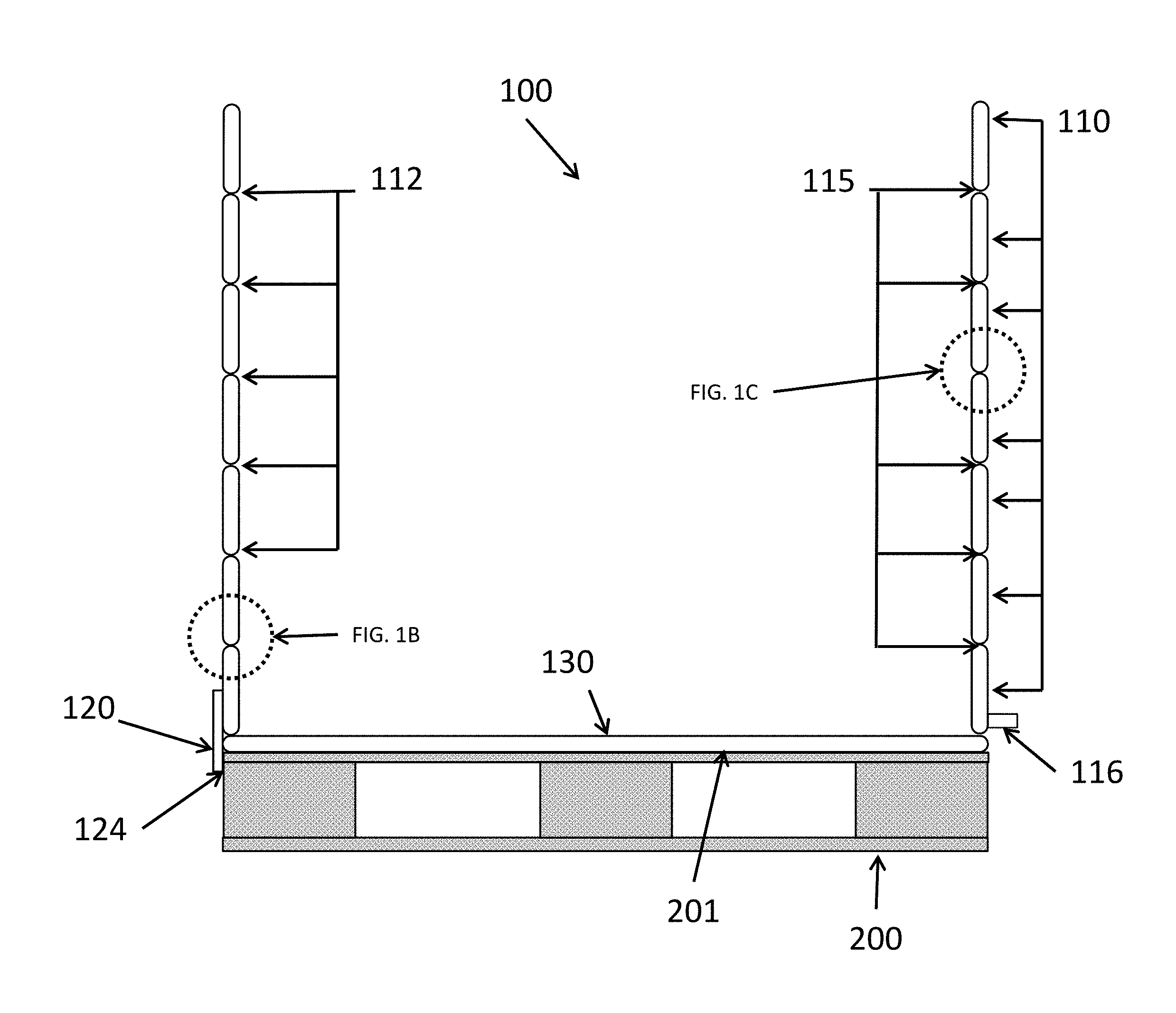
[0014] FIG. 1A illustrates a cutaway view of an inflatable system 100 for securing cargo on a pallet 200 in accordance with embodiments of the present disclosure. FIGS. 1B and 1C show magnified views of portions of FIG. 1A. The system 100 can include two or more inflatable members 110 that extend about a perimeter of the pallet 200. The inflatable members 110 are arranged in a stack having a vertical configuration when the inflatable members are inflated and are fluidically connected by inlet passages 112 and outlet passages 115. Each of the inflatable members 110 forms a segment in the stack. A pressure regulator 152 is located in each of the inlet passages 112 to facilitate ordered filling of the inflatable members 110 from a lowest member in the stack to a highest member in the stack, and at least one check valve 155 is located in each of the outlet passages 115 to facilitated draining of fluid from the inflatable members 110. A securement strap 120 can be attached to a fastener 124 and at least one of the inflatable members 110 to secure the system 100 to the pallet 200. When the inflatable members 110 are inflated through an inlet port 116 located on the lowest inflatable member 110, the fastener 124 is secured to the pallet 200 and the inflatable members 110 form a wall extending vertically from the perimeter of the pallet 200 to surround cargo on the pallet 200. In some embodiments, the inflatable members 200 can be selectively deflated from highest to lowest to provide lateral access to cargo on the pallet 200.
[0015] In some embodiments, each inflatable member 110 can extend about the perimeter of the pallet 200 as a single piece or as multiple independent or interconnected sections. Each inflatable member 110 is interconnected with a neighboring or adjacent inflatable member through inlet passages 112 and outlet passages 115. The inlet passages 112 and outlet passages 115 are configured to selectively allow a fluid (e.g., a gas or liquid) to flow therethrough or prohibit a fluid from flowing therethrough.
[0016] In some embodiments, the inflatable members 110 can be filled with a temperature-controlled liquid. In some embodiments, the inflatable members 110 can be filled with a heated liquid to help stabilize or influence the temperature of the cargo. For example, the inflatable members 110 can be filed with the heated liquid to protect cargo against cold external conditions or to maintain heated cargo at an elevated temperature. In some embodiments, the inflatable members 110 can be filed with a cooled liquid to help stabilize the temperature of the cargo. For example, filling the inflatable members 110 with a cooled liquid can assist with cold chain constraints while the pallet of cargo is en route between destinations or is temporarily sitting on a loading dock.
[0017] As shown in FIG. 1B, the pressure regulator 152 located in each of the inlet passages 112 can prevent fluid from flowing through the inlet passage 112 until a threshold pressure is reached. The value of the threshold pressure can depend upon the substance being used to fill the inflatable members 110 as well as the material composition of the inflatable members 110. For example, more pliable materials can utilize a lower threshold pressure while less pliable materials will use a higher pressure. In various embodiments, the threshold pressure can be in a range from 25-150 psi. In one embodiment, the inflatable members 110 can include butyl rubber (polyisobutylene), and the threshold pressure can be in a range of 25 to 60 psi. In another embodiment, the inflatable members 110 can include nylon-reinforced composite rubber, and the threshold pressure can be in a range of 40-80 psi. In a further embodiment, the inflatable members 110 can include a material suitable for use as a hydroforming bladder such as polyurethane or urethane, and the threshold pressure can be greater than 100 psi. In accordance with various embodiments, the pressure regulator 152 can include a spring actuator connected to a valve. The spring can open the valve once the threshold fluid pressure is applied against the spring. In some embodiments, the tension on the spring can be adjusted to adjust the threshold pressure. For example, a screw connected to the spring can be turned to increase or decrease the tension on the spring. In other embodiments, the pressure regulator 152 can include a spring-loaded flap or valve body. The pressure regulators 152 and inlet passages 112 are illustrated as lining up vertically with respect to one another at one side or corner of the system 100 in FIGS. 1A and 4. However, the pressure regulators 152 and inlet passages 112 can be located at any position around the perimeter of each inflatable member 110. In some embodiments, the inlet passage 112 between first and second inflatable members 110 is located at a position diametrically opposed to the inlet passage between second and third inflatable members 110. Distribution of the inlet passages 112 around the perimeter of the system 100 can promote even filling of each inflatable member 110 and mitigate filling blockages that could be caused by folds or creases in an inflatable member 110.
[0018] The inflatable members 110 can be configured to have an inflated state and a deflated state. For example, FIG. 1A illustrates the system 100 with all inflatable members 110 in an inflated state while FIG. 2 illustrates the system 100 with inflatable members 110a-110g in a deflated state. FIG. 3 illustrates the system 100 with inflatable members 110a-110c that are inflated and inflatable members 110d-110g that are deflated. The inflatable members 110 can be stacked one atop another as segments in a vertical configuration. In some embodiments, the pressure regulator 152 located in the inlet passage 112 between a lower inflatable member 110 and a higher neighboring inflatable member 110 in the vertical stack (e.g., adjacent inflatable members in the stack such as inflatable members 110a and 110b or inflatable members 110b and 110c) can prevent fluid from passing from the lower inflatable member to the higher inflatable member 110 through the inlet passage 112 until the threshold pressure is reached in the lower inflatable member 110. That is, the arrangement of pressure regulators 152 can cause the inflatable members 110 to inflate sequentially from a lowest member 110a in the stack to a highest member 110g in the vertical stack in some embodiments. The sequential inflation of the inflatable members 110 from lowest to highest enables securement of cargo 250 on the pallet 200 from the earliest stages of loading the pallet. For example, cargo 250 can be added to form a lowest layer 250a on the pallet. Before stacking additional cargo atop the lowest layer 250a, the lowest inflatable member 110a and adjacent inflatable members 110b in the stack can be fully inflated as necessary to protect and secure that lowest layer 250a of cargo. The filling of the system 100 can then be halted while an additional layer 250b of cargo 250 is added. In this way, the cargo is secured level by level by sequentially inflating the inflatable members 110a-110g as each cargo layer 250a-250d is completed. In some embodiments, the system 100 can include redundant pressure regulators 152 within each inlet passage 112 or in multiple inlet passages between the same inflatable members 110. The redundancy in pressure regulators 152 can allow the system 100 to continue inflation in the event that a single regulator seizes or fails.
[0019] As shown in FIG. 1C, at least one check valve 155 can be located in each outlet passage 115 to facilitate ordered draining of fluid from the inflatable members 110a-110g. In some embodiments, the check valve 155 can optionally include a side port 156. The check valve(s) 155 can include relief valves that are manually or automatically actuated. During a deflation of the system, the check valves 155 can be used to drain fluid from the inflatable members 110. For example, the inlet port 116 can be opened to allow fluid to exit the lowest inflatable member 110a. As the pressure drops inside the lowest inflatable member 110a, fluid passes through the check valves 155 from inflatable members 110b-110g that are vertically stacked above the lowest inflatable member 110a. This process of fluid flow from highest inflatable member 110g to lowest inflatable member 110a and through the inlet port 116 can draw all of the fluid out of the system. In some embodiments, the system 100 can include redundant check valves 155 within each outlet passage 115 or in multiple outlet passages 115 between the same inflatable members 110. The redundancy in check valves 155 can allow the system 100 to continue deflating in the event that a single check valve seizes or fails.
[0020] In some embodiments, draining of the system can take time as each inflatable member 110 slowly drains to relieve pressure once the check valves are opened. In some embodiments, the system 100 can include a vacuum source attached to each check valve 155 to remove the fluid in each inflatable member 110. The vacuum source can more quickly remove the fluid from the inflatable members 110 to speed up the collapse of the inflatable members, for example, for repacking of the system 100 when it is no longer needed.
[0021] In some embodiments, the check valve 155 can vent the contents of an inflatable member directly to the outside environment through the side port 156. In some embodiments, the side port 156 can include a drainage port with a manual plug. In some embodiments, a vacuum source can be connected directly to each check valve 155 individually to draw the fluid out of the inflatable members 110 to which it is connected. If the inflatable members 110 are vented directly to the outside environment through the side port 156, the inflatable members 110 can be selectively deflated in some embodiments. For example, the inflatable members 110 can be deflated in order from top to bottom or one-at-a-time in any order (not necessarily in order of how the members are stacked). In some embodiments, the sequential deflation of the inflatable members 110a-g from highest to lowest enables lateral access to higher layers of stacked cargo while the system 100 continues to secure lower layers of stacked cargo. For example, cargo may be offloaded from the pallet over a period of time in some situations as needed to replenish supplies or to fulfill orders. To remove the highest layer 250d of cargo 250, the highest inflatable member 110g can be deflated to allow lateral access to the highest layer 250d. As the higher layers are depleted and access is needed to lower layers, progressively lower inflatable members 110a-110f can be sequentially deflated. During this process, the lowest levels of stacked cargo remain secured by the system 100.
[0022] The inflatable members 110 can be made of any suitable material including, but not limited to, pliable rubbers, silicone, plastics, or other materials that are capable of being inflated to hold air, liquid, or other fluids as appropriate. In some embodiments, the inflatable members 110 can be puncture resistant to prevent inadvertent deflation should the inflatable member 110 come into contact with a sharp object. For example, the inflatable members 110 can be formed of a tough, rubbery material. In some embodiments, the inflatable members 110 can be formed of a pliable material that can be easily folded away and stowed when the system 100 is not in use. For example, the inflatable members 110 can be formed of a lightweight plastic material. In some embodiments, the inflatable members 110 can be compacted or bailed to allow compact transport or storage of the system 100 when not in use.
[0023] In some embodiments, a reinforcing wire ring 118 can be located at each intersection between inflatable members 110. The reinforcing wire ring 118 can provide lateral rigidity to the inflatable members 110 in some embodiments. In some embodiments, a shape of the perimeter of the inflatable members 110 can conform to a shape of the reinforcing wire ring 118. In some embodiments, the reinforcing wire ring can be internal to each inflatable member 110 and can be located adjacent to the intersection point at which the inflatable member 110 connects to an adjacent inflatable member 100.
[0024] An inlet port 116 can be located on the lowest of the inflatable members 110 in the vertical stack. In some embodiments, the inlet port 116 can be configured to connect with a fluid pump or other fluid source. For example, the inlet port 116 can include screw threads, pipe fittings, or valves such as needle valves to facilitate connection to hoses or tubes leading to the fluid pump.
[0025] In some embodiments, the system 100 can include a base 130 that is laid over a cargo-supporting surface 201 of the pallet 200. In some embodiments, the base 130 can be attached to the lowest inflatable member 110a in the vertical stack. The base 130 can help stabilize the system 100 with respect to the pallet 200 by preventing shifting of the inflatable members 110 with respect to the pallet 200 particularly when cargo has been placed onto the pallet 200. For example, the weight of cargo resting on the base 130 can pin the base 130 in place and prevent shifting or movement of the system 100 with respect to the pallet 200. In various embodiments, the base 130 and inflatable members 110 can be provided as a single unit. Alternatively, the base 130 and inflatable members 110 can be provided separately and can be attached by a user at the time of installation of the system 100.
[0026] The securement strap 120 attached to the fastener 124 can selectively secure one or more inflatable members 110 to the pallet 200. The operation of the securement strap is shown in detail in FIGS. 5A-5B and 6A-6B. In some embodiments, the securement strap 120 can include reinforced canvas or fabric to provide strength and flexibility to the strap. In some embodiments, the securement strap 120 can attach to at least one of the inflatable members 110 at an attachment point 122. For example, the securement strap 120 can be attached using robust stitching, adhesives, or other suitable attachment mechanisms. In some embodiments, a portion of the securement strap 120 can be attached to the inflatable member 110 using a heating or melting process that seals the securement strap 120 to the inflatable member 110 at the attachment point 122. In some embodiments, the securement strap 120 can be attached to the lowest inflatable member 110a in the vertical stack.
[0027] FIGS. 5A and 5B show front and side cutaway views, respectively, of the system 100 for securing cargo to a pallet before the securement strap 120 has been secured to the pallet 200. As shown, the inflatable member 110a is not inflated to its maximum extent, and the securement strip 120 hangs below the cargo-supporting surface 201 of the pallet. As the inflatable member 110 is inflated, the securement strap 120 is carried upward due to its attachment at the attachment point 122.
[0028] FIGS. 6A and 6B show front and side cutaway views, respectively, of the system of FIGS. 5A and 5B when the inflatable member 110a has been inflated to its fullest extent (i.e., the pressure inside the inflatable member has reached the threshold pressure value such that the pressure regulator is allowing any additional fluid to pass into adjacent inflatable members through the inlet passage 112). As illustrated in these figures, the fastener 124 attached to the securement strap 120 eventually contacts the underside of the cargo-supporting surface 201 of the pallet 200 as the inflatable member 110 is filled. As the pressure reaches the threshold pressure level and the inflatable member inflates to its greatest extent, tension is created in the securement strap 120 between the attachment point 122 and the fastener 124 that secures or latches the fastener 124 to the pallet 200.
[0029] In various embodiments, the fastener 124 can include a variety of shapes including clamps, hooks, cleats, spikes, nails, screws, or other suitable fastening forms. In various embodiments, the fastener 124 can be formed of a variety of materials including metals (e.g., steel, iron, or aluminum) or plastics. In exemplary embodiments, the fastener 124 can be formed of a harder material than the material that forms the pallet 200. For example, the fastener 124 can be formed of metal when the pallet 200 is formed of wood.
[0030] In describing exemplary embodiments, specific terminology is used for the sake of clarity. For purposes of description, each specific term is intended to at least include all technical and functional equivalents that operate in a similar manner to accomplish a similar purpose. Additionally, in some instances where a particular exemplary embodiment includes a plurality of system elements, device components or method steps, those elements, components or steps may be replaced with a single element, component, or step Likewise, a single element, component, or step may be replaced with a plurality of elements, components, or steps that serve the same purpose. Moreover, while exemplary embodiments have been shown and described with references to particular embodiments thereof, those of ordinary skill in the art will understand that various substitutions and alterations in form and detail may be made therein without departing from the scope of the present disclosure. Further still, other aspects, functions, and advantages are also within the scope of the present disclosure.
[0031] Exemplary flowcharts are provided herein for illustrative purposes and are non-limiting examples of methods. One of ordinary skill in the art will recognize that exemplary methods may include more or fewer steps than those illustrated in the exemplary flowcharts, and that the steps in the exemplary flowcharts may be performed in a different order than the order shown in the illustrative flowcharts.
* * * * *
D00000
D00001
D00002
D00003
D00004
D00005
D00006
D00007
XML
uspto.report is an independent third-party trademark research tool that is not affiliated, endorsed, or sponsored by the United States Patent and Trademark Office (USPTO) or any other governmental organization. The information provided by uspto.report is based on publicly available data at the time of writing and is intended for informational purposes only.
While we strive to provide accurate and up-to-date information, we do not guarantee the accuracy, completeness, reliability, or suitability of the information displayed on this site. The use of this site is at your own risk. Any reliance you place on such information is therefore strictly at your own risk.
All official trademark data, including owner information, should be verified by visiting the official USPTO website at www.uspto.gov. This site is not intended to replace professional legal advice and should not be used as a substitute for consulting with a legal professional who is knowledgeable about trademark law.