Systems And Methods For Estimating Clinical Effects Of Electrical Stimulation
Blum; David ; et al.
U.S. patent application number 16/031555 was filed with the patent office on 2019-01-17 for systems and methods for estimating clinical effects of electrical stimulation. The applicant listed for this patent is Boston Scientific Neuromodulation Corporation. Invention is credited to David Blum, Peter J. Yoo.
| Application Number | 20190015039 16/031555 |
| Document ID | / |
| Family ID | 63036461 |
| Filed Date | 2019-01-17 |


| United States Patent Application | 20190015039 |
| Kind Code | A1 |
| Blum; David ; et al. | January 17, 2019 |
SYSTEMS AND METHODS FOR ESTIMATING CLINICAL EFFECTS OF ELECTRICAL STIMULATION
Abstract
A method for generating a clinical effects map for electrical stimulation using an electrical stimulation lead includes receiving at least one clinical response for stimulation using each of multiple first sets of stimulation parameters where each clinical response is associated with at least one therapeutic effect or side effect. The method also includes determining, using the clinical responses and the first sets of stimulation parameters, a spatial relationship between the electrical stimulation lead and at least one effect region, where each effect region is associated with at least one of the therapeutic effects or side effects; estimating, based on the spatial relationship, at least one clinical response for each of multiple second sets of stimulation parameters; and generating and presenting a clinical effects map illustrating at least the estimated clinical response for one or more of the second sets of stimulation parameters.
| Inventors: | Blum; David; (Boston, MA) ; Yoo; Peter J.; (Burbank, CA) | ||||||||||
| Applicant: |
|
||||||||||
|---|---|---|---|---|---|---|---|---|---|---|---|
| Family ID: | 63036461 | ||||||||||
| Appl. No.: | 16/031555 | ||||||||||
| Filed: | July 10, 2018 |
Related U.S. Patent Documents
| Application Number | Filing Date | Patent Number | ||
|---|---|---|---|---|
| 62532869 | Jul 14, 2017 | |||
| Current U.S. Class: | 1/1 |
| Current CPC Class: | A61N 1/0529 20130101; A61N 1/36175 20130101; A61N 1/36132 20130101; G06T 7/30 20170101; A61B 5/4848 20130101; A61N 1/36146 20130101; A61N 1/36135 20130101; G06T 7/70 20170101 |
| International Class: | A61B 5/00 20060101 A61B005/00; A61N 1/05 20060101 A61N001/05; A61N 1/36 20060101 A61N001/36; G06T 7/30 20060101 G06T007/30; G06T 7/70 20060101 G06T007/70 |
Claims
1. A system for generating a clinical effects map for electrical stimulation, the system comprising: a display; and a processor coupled to the display and configured to perform actions comprising: receiving, for each of a plurality of first sets of stimulation parameters, at least one clinical response resulting from stimulation using the first set of stimulation parameters, wherein each first set of stimulation parameters comprises a selection of at least one electrode of an electrical stimulation lead to generate the stimulation, wherein each of the at least one clinical response is associated with at least one therapeutic effect or side effect; determining, using the clinical responses and the first sets of stimulation parameters, a spatial relationship between the electrical stimulation lead and at least one effect region, wherein each effect region is associated with at least one of the at least one therapeutic effect or side effect; estimating, based on the spatial relationship, at least one clinical response for each of a plurality of second sets of stimulation parameters which are different from the first sets of stimulation parameters; and generating and presenting, on the display, a clinical effects map illustrating at least the estimated clinical response for each of a plurality of the second sets of stimulation parameters.
2. The system of claim 1, wherein determining the spatial relationship comprises estimating, for at least one of the first sets of stimulation parameters, a region of tissue stimulated by the stimulation lead using that first set of stimulation parameters.
3. The system of claim 2, wherein estimating the region comprising determining a stimulation field model (SFM) for that first set of stimulation parameters.
4. The system of claim 2, wherein determining the spatial relationship further comprises estimating a degree of overlap between the estimated region of tissue stimulated by one of the first sets of stimulation parameters and a one of the at least one effect region based on the clinical response resulting from stimulation using the one of the first sets of stimulation parameters.
5. The system of claim 1, wherein estimating at least one clinical response comprises estimating, for at least one of the second sets of stimulation parameters, a region of tissue stimulated by the stimulation lead using that second set of stimulation parameters.
6. The system of claim 5, wherein estimating the region comprising determining a stimulation field model (SFM) for that second set of stimulation parameters.
7. The system of claim 5, wherein estimating at least one clinical response further comprises determining a degree of overlap between the estimate region of tissue stimulated by one of the second sets of stimulation parameters and a one of the at least one effect region.
8. The system of claim 7, wherein estimating at least one clinical response further comprises estimating a degree of the clinical response based on the degree of overlap.
9. The system of claim 1, wherein determining the spatial relationship comprises receiving an image identifying a position of the lead and an atlas comprising the at least one effect region.
10. The system of claim 9, wherein determining the spatial relationship further comprises aligning the atlas with the image.
11. The system of claim 10, wherein determining the spatial relationship further comprises, after aligning the atlas with the image, modifying the spatial relationship using the received clinical responses.
12. A system for selecting stimulation parameters, the system comprising: the system of claim 1, wherein the actions further comprise receiving a selection of an entry on the clinical effects map; and initiating a signal to provide a pulse generator with a selected set of stimulation parameters corresponding to the selected entry to generate stimulation using the selected set of stimulation parameters.
13. The system of claim 12, further comprising the pulse generator; and the electrical stimulation lead coupled to the pulse generator.
14. A non-transitory computer-readable medium having computer executable instructions stored thereon that, when executed by at least one processor, cause the at least one processor to perform actions comprising: receiving, for each of a plurality of first sets of stimulation parameters, at least one clinical response resulting from stimulation using the first set of stimulation parameters, wherein each first set of stimulation parameters comprises a selection of at least one electrode of an electrical stimulation lead to generate the stimulation, wherein each of the at least one clinical response is associated with at least one therapeutic effect or side effect; determining, using the clinical responses and the first sets of stimulation parameters, a spatial relationship between the electrical stimulation lead and at least one effect region, wherein each effect region is associated with at least one of the at least one therapeutic effect or side effect; estimating, based on the spatial relationship, at least one clinical response for each of a plurality of second sets of stimulation parameters which are different from the first sets of stimulation parameters; and generating and presenting, on a display, a clinical effects map illustrating at least the estimated clinical response for each of a plurality of the second sets of stimulation parameters.
15. The non-transitory computer-readable medium of claim 14, wherein the actions further comprise receiving a selection of an entry on the clinical effects map; and initiating a signal to provide a pulse generator with a selected set of stimulation parameters corresponding to the selected entry to generate stimulation using the selected set of stimulation parameters.
16. A method for generating a clinical effects map for electrical stimulation, the method comprising: receiving, for each of a plurality of first sets of stimulation parameters, at least one clinical response resulting from stimulation using the first set of stimulation parameters, wherein each first set of stimulation parameters comprises a selection of at least one electrode of an electrical stimulation lead to generate the stimulation, wherein each of the at least one clinical response is associated with at least one therapeutic effect or side effect; determining, using the clinical responses and the first sets of stimulation parameters, a spatial relationship between the electrical stimulation lead and at least one effect region, wherein each effect region is associated with at least one of the at least one therapeutic effect or side effect; estimating, based on the spatial relationship, at least one clinical response for each of a plurality of second sets of stimulation parameters which are different from the first sets of stimulation parameters; and generating and presenting, on a display, a clinical effects map illustrating at least the estimated clinical response for each of a plurality of the second sets of stimulation parameters.
17. The method of claim 16, further comprising receiving a selection of an entry on the clinical effects map; and initiating a signal to provide a pulse generator with a selected set of stimulation parameters corresponding to the selected entry to generate stimulation using the selected set of stimulation parameters.
18. The method of claim 16, wherein estimating at least one clinical response comprises estimating, for at least one of the second sets of stimulation parameters, a region of tissue stimulated by the stimulation lead using that second set of stimulation parameters.
19. The method of claim 18, wherein estimating at least one clinical response further comprises determining a degree of overlap between the estimate region of tissue stimulated by one of the second sets of stimulation parameters and a one of the at least one effect region.
20. The method of claim 19, wherein estimating at least one clinical response further comprises estimating a degree of the clinical response based on the degree of overlap.
Description
CROSS-REFERENCE TO RELATED APPLICATIONS
[0001] This application claims the benefit under 35 U.S.C. .sctn. 119(e) of U.S. Provisional Patent Application Ser. No. 62/532,869, filed Jul. 14, 2017, which is incorporated herein by reference.
FIELD
[0002] The present invention is directed to the area of implantable electrical stimulation systems and methods of making and using the systems. The present invention is also directed to systems and methods for estimating clinical effects of electrical stimulation.
BACKGROUND
[0003] Implantable electrical stimulation systems have proven therapeutic in a variety of diseases and disorders. For example, spinal cord stimulation systems have been used as a therapeutic modality for the treatment of chronic pain syndromes. Peripheral nerve stimulation has been used to treat chronic pain syndrome and incontinence, with a number of other applications under investigation. Functional electrical stimulation systems have been applied to restore some functionality to paralyzed extremities in spinal cord injury patients. Stimulation of the brain, such as deep brain stimulation, can be used to treat a variety of diseases or disorders.
[0004] Stimulators have been developed to provide therapy for a variety of treatments. A stimulator can include a control module (with a pulse generator), at least one lead, and an array of stimulator electrodes on each lead. The stimulator electrodes are in contact with or near the nerves, muscles, or other tissue to be stimulated. The pulse generator in the control module generates electrical pulses that are delivered by the electrodes to body tissue.
BRIEF SUMMARY
[0005] A system for generating a clinical effects map for electrical stimulation. The system includes a display; and a processor coupled to the display and configured to perform actions. The actions include receiving, for each of multiple first sets of stimulation parameters, at least one clinical response resulting from stimulation using the first set of stimulation parameters, where each first set of stimulation parameters includes a selection of at least one electrode of an electrical stimulation lead to generate the stimulation and where each of the at least one clinical response is associated with at least one therapeutic effect or side effect. The actions also include determining, using the clinical responses and the first sets of stimulation parameters, a spatial relationship between the electrical stimulation lead and at least one effect region, where each effect region is associated with at least one of the at least one therapeutic effect or side effect; estimating, based on the spatial relationship, at least one clinical response for each of multiple second sets of stimulation parameters which are different from the first sets of stimulation parameters; and generating and presenting, on the display, a clinical effects map illustrating at least the estimated clinical response for each of a plurality of the second sets of stimulation parameters.
[0006] Another embodiment is a non-transitory computer-readable medium having computer executable instructions stored thereon that, when executed by at least one processor, cause the at least one processor to perform actions. The actions include receiving, for each of multiple first sets of stimulation parameters, at least one clinical response resulting from stimulation using the first set of stimulation parameters, where each first set of stimulation parameters includes a selection of at least one electrode of an electrical stimulation lead to generate the stimulation and where each of the at least one clinical response is associated with at least one therapeutic effect or side effect. The actions also include determining, using the clinical responses and the first sets of stimulation parameters, a spatial relationship between the electrical stimulation lead and at least one effect region, where each effect region is associated with at least one of the at least one therapeutic effect or side effect; estimating, based on the spatial relationship, at least one clinical response for each of multiple second sets of stimulation parameters which are different from the first sets of stimulation parameters; and generating and presenting, on a display, a clinical effects map illustrating at least the estimated clinical response for each of a plurality of the second sets of stimulation parameters.
[0007] Yet another embodiment is a method for generating a clinical effects map for electrical stimulation. The method includes receiving, for each of multiple first sets of stimulation parameters, at least one clinical response resulting from stimulation using the first set of stimulation parameters, where each first set of stimulation parameters includes a selection of at least one electrode of an electrical stimulation lead to generate the stimulation and where each of the at least one clinical response is associated with at least one therapeutic effect or side effect. The method also includes determining, using the clinical responses and the first sets of stimulation parameters, a spatial relationship between the electrical stimulation lead and at least one effect region, where each effect region is associated with at least one of the at least one therapeutic effect or side effect; estimating, based on the spatial relationship, at least one clinical response for each of multiple second sets of stimulation parameters which are different from the first sets of stimulation parameters; and generating and presenting, on a display, a clinical effects map illustrating at least the estimated clinical response for each of a plurality of the second sets of stimulation parameters.
[0008] In at least some embodiments of the system, computer-readable medium, or method, the actions or method further include receiving a selection of an entry on the clinical effects map; and initiating a signal to provide a pulse generator with a selected set of stimulation parameters corresponding to the selected entry to generate stimulation using the selected set of stimulation parameters. These embodiments may also be a system, computer-readable medium, or method for generating stimulation parameters for electrical stimulation.
[0009] In at least some embodiments of the system, computer-readable medium, or method, determining the spatial relationship includes estimating, for at least one of the first sets of stimulation parameters, a region of tissue stimulated by the stimulation lead using that first set of stimulation parameters. In at least some embodiments of the system, computer-readable medium, or method, estimating the region including determining a stimulation field model (SFM) for that first set of stimulation parameters. In at least some embodiments of the system, computer-readable medium, or method, determining the spatial relationship further includes estimating a degree of overlap between the estimated region of tissue stimulated by one of the first sets of stimulation parameters and a one of the at least one effect region based on the clinical response resulting from stimulation using the one of the first sets of stimulation parameters.
[0010] In at least some embodiments of the system, computer-readable medium, or method, estimating at least one clinical response includes estimating, for at least one of the second sets of stimulation parameters, a region of tissue stimulated by the stimulation lead using that second set of stimulation parameters. In at least some embodiments of the system, computer-readable medium, or method, estimating the region including determining a stimulation field model (SFM) for that second set of stimulation parameters. In at least some embodiments of the system, computer-readable medium, or method, estimating at least one clinical response further includes determining a degree of overlap between the estimate region of tissue stimulated by one of the second sets of stimulation parameters and a one of the at least one effect region. In at least some embodiments of the system, computer-readable medium, or method, estimating at least one clinical response further includes estimating a degree of the clinical response based on the degree of overlap.
[0011] In at least some embodiments of the system, computer-readable medium, or method, determining the spatial relationship includes receiving an image identifying a position of the lead and an atlas including the at least one effect region. In at least some embodiments of the system, computer-readable medium, or method, determining the spatial relationship further includes aligning the atlas with the image. In at least some embodiments of the system, computer-readable medium, or method, determining the spatial relationship further includes, after aligning the atlas with the image, modifying the spatial relationship using the received clinical responses.
[0012] In at least some embodiments of the system, the system further includes a pulse generator; and the electrical stimulation lead coupled to the pulse generator.
BRIEF DESCRIPTION OF THE DRAWINGS
[0013] Non-limiting and non-exhaustive embodiments of the present invention are described with reference to the following drawings. In the drawings, like reference numerals refer to like parts throughout the various figures unless otherwise specified.
[0014] For a better understanding of the present invention, reference will be made to the following Detailed Description, which is to be read in association with the accompanying drawings, wherein:
[0015] FIG. 1 is a schematic view of one embodiment of an electrical stimulation system, according to the invention;
[0016] FIG. 2 is a schematic side view of one embodiment of an electrical stimulation lead, according to the invention;
[0017] FIG. 3 is a schematic block diagram of one embodiment of a system for automatically aligning brain atlases using clinical responses, according to the invention;
[0018] FIG. 4 is a flowchart of one embodiment of a method of determining a spatial relationship between a lead and effect regions using clinical responses, according to the invention;
[0019] FIG. 5 illustrated one embodiment of the method of FIG. 4 using a portion of an atlas and an image, according to the invention;
[0020] FIG. 6 illustrates one embodiment of a clinical effects map, according to the invention;
[0021] FIG. 7 illustrates another embodiment of a clinical effects map, according to the invention;
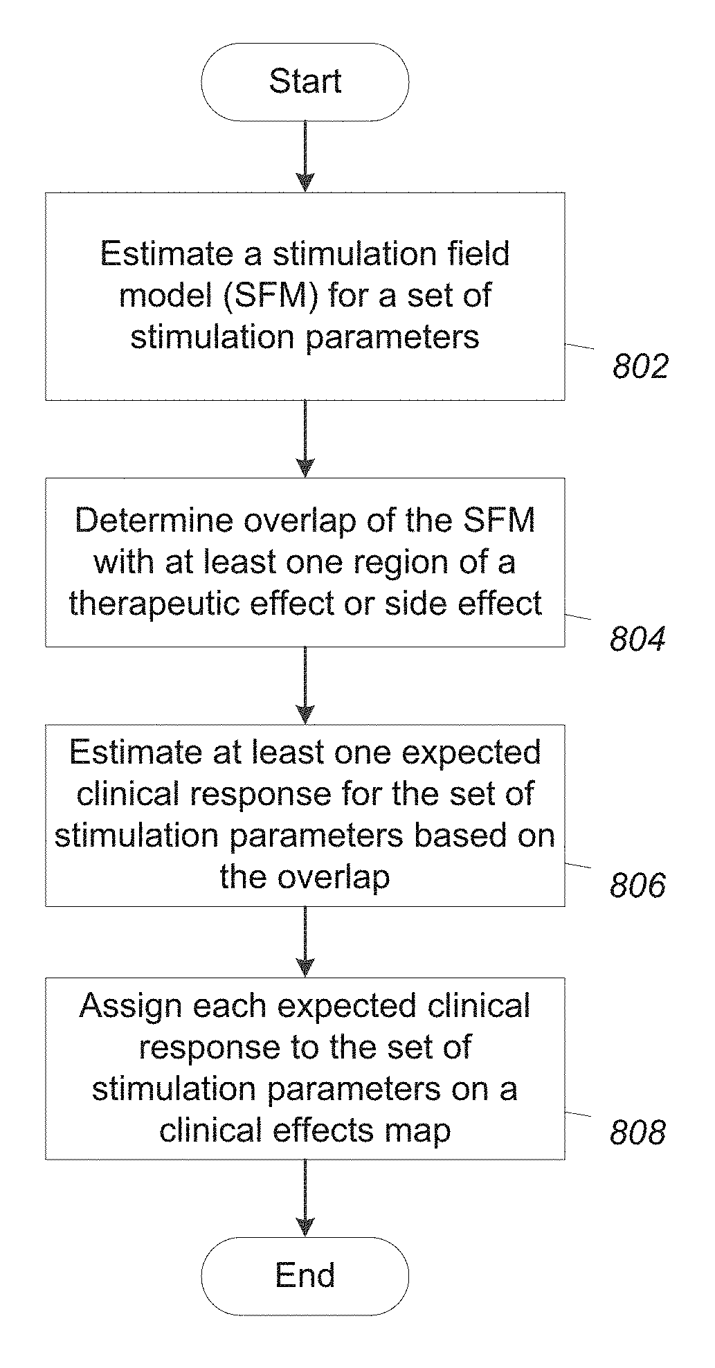
[0022] FIG. 8 is a flowchart of one embodiment of a method of estimating clinical responses for sets of stimulation parameters, according to the invention; and
[0023] FIG. 9 is a flowchart of one embodiment of a method of generating a clinical effects map for electrical stimulation, according to the invention.
DETAILED DESCRIPTION
[0024] The present invention is directed to the area of implantable electrical stimulation systems and methods of making and using the systems. The present invention is also directed to systems and methods for estimating clinical effects of electrical stimulation.
[0025] Suitable implantable electrical stimulation systems include, but are not limited to, a least one lead with at least one electrode disposed on a distal end portion of the lead and at least one terminal disposed on at least one proximal end portion of the lead. Leads include, for example, percutaneous leads, paddle leads, cuff leads, or any other arrangement of electrodes on a lead. Examples of electrical stimulation systems with leads are found in, for example, U.S. Pat. Nos. 6,181,969; 6,516,227; 6,609,029; 6,609,032; 6,741,892; 7,244,150; 7,450,997; 7,672,734; 7,761,165; 7,783,359; 7,792,590; 7,809,446; 7,949,395; 7,974,706; 8,175,710; 8,224,450; 8,271,094; 8,295,944; 8,364,278; 8,391,985; and 8,688,235; and U.S. Patent Applications Publication Nos. 2007/0150036; 2009/0187222; 2009/0276021; 2010/0076535; 2010/0268298; 2011/0005069; 2011/0004267; 2011/0078900; 2011/0130817; 2011/0130818; 2011/0238129; 2011/0313500; 2012/0016378; 2012/0046710; 2012/0071949; 2012/0165911; 2012/0197375; 2012/0203316; 2012/0203320; 2012/0203321; 2012/0316615; 2013/0105071; and 2013/0197602, all of which are incorporated by reference. In the discussion below, a percutaneous lead will be exemplified, but it will be understood that the methods and systems described herein are also applicable to paddle leads and other leads.
[0026] A lead for electrical stimulation (for example, deep brain or spinal cord stimulation) includes stimulation electrodes that can be ring electrodes, segmented electrodes that extend only partially around the circumference of the lead, or any other type of electrode, or any combination thereof. The segmented electrodes can be provided in sets of electrodes, with each set having electrodes circumferentially distributed about the lead at a particular longitudinal position or across a particular longitudinal region. For illustrative purposes, the leads are described herein relative to use for deep brain stimulation, but it will be understood that any of the leads can be used for applications other than deep brain stimulation, including spinal cord stimulation, peripheral nerve stimulation, or stimulation of other nerves, muscles, and tissues. In particular, stimulation may stimulate specific targets. Examples of such targets include, but are not limited to, the subthalamic nucleus (STN), internal segment of the globus pallidus (GPi), external segment of the globus pallidus (GPe), and the like. In at least some embodiments, an anatomical structure is defined by its physical structure and a physiological target is defined by its functional attributes. In at least some embodiments, the lead may be positioned at least partially within the target, but in other embodiments, the lead may be near, but not inside, the target. The stimulation of tissue can include, but is not limited to, one or more of activation, inhibition, depression, or other modulation of the stimulated tissue.
[0027] Turning to FIG. 1, one embodiment of an electrical stimulation system 10 includes at least one stimulation lead 12 and an implantable pulse generator (IPG) 14. The system 10 can also include at least one of an external remote control (RC) 16, a clinician's programmer (CP) 18, an external trial stimulator (ETS) 20, or an external charger 22.
[0028] The IPG 14 is physically connected, optionally via at least one lead extension 24, to the stimulation lead(s) 12. Each lead carries multiple electrodes 26 arranged in an array. The IPG 14 includes pulse generation circuitry that delivers electrical stimulation energy in the form of, for example, a pulsed electrical waveform (i.e., a temporal series of electrical pulses) to the electrode array 26 in accordance with a set of stimulation parameters. The IPG 14 can be implanted into a patient's body, for example, below the patient's clavicle area or within the patient's buttocks or abdominal cavity. The IPG 14 can have eight stimulation channels which may be independently programmable to control the magnitude of the current stimulus from each channel. In at least some embodiments, the IPG 14 can have more or fewer than eight stimulation channels (for example, 4, 6, 16, 32, or more stimulation channels). The IPG 14 can have one, two, three, four, or more connector ports, for receiving the terminals of the leads.
[0029] The ETS 20 may also be physically connected, optionally via the percutaneous lead extensions 28 and external cable 30, to the stimulation leads 12. The ETS 20, which may have similar pulse generation circuitry as the IPG 14, also delivers electrical stimulation energy in the form of, for example, a pulsed electrical waveform to the electrode array 26 in accordance with a set of stimulation parameters. One difference between the ETS 20 and the IPG 14 is that the ETS 20 is often a non-implantable device that is used on a trial basis after the neurostimulation leads 12 have been implanted and prior to implantation of the IPG 14, to test functioning of the system or the responsiveness of the stimulation that is to be provided. Any functions described herein with respect to the IPG 14 can likewise be performed with respect to the ETS 20.
[0030] The RC 16 may be used to telemetrically communicate with or control the IPG 14 or ETS 20 via a uni- or bi-directional wireless communications link 32. Once the IPG 14 and neurostimulation leads 12 are implanted, the RC 16 may be used to telemetrically communicate with or control the IPG 14 via a uni- or bi-directional communications link 34. Such communication or control allows the IPG 14 to be turned on or off and to be programmed with different stimulation parameter sets. The IPG 14 may also be operated to modify the programmed stimulation parameters to actively control the characteristics of the electrical stimulation energy output by the IPG 14. The CP 18 allows a user, such as a clinician, the ability to program stimulation parameters for the IPG 14 and ETS 20 in the operating room and in follow-up sessions.
[0031] The CP 18 may perform this function by indirectly communicating with the IPG 14 or ETS 20, through the RC 16, via a wireless communications link 36. Alternatively, the CP 18 may directly communicate with the IPG 14 or ETS 20 via a wireless communications link (not shown). The stimulation parameters provided by the CP 18 are also used to program the RC 16, so that the stimulation parameters can be subsequently modified by operation of the RC 16 in a stand-alone mode (i.e., without the assistance of the CP 18).
[0032] For purposes of brevity, the details of the RC 16, CP 18, ETS 20, and external charger 22 will not be further described herein. Details of exemplary embodiments of these devices are disclosed in U.S. Pat. No. 6,895,280, which is expressly incorporated herein by reference. Other examples of electrical stimulation systems can be found at U.S. Pat. Nos. 6,181,969; 6,516,227; 6,609,029; 6,609,032; 6,741,892; 7,949,395; 7,244,150; 7,672,734; and U.S. Pat. Nos. 7,761,165; 7,974,706; 8,175,710; 8,224,450; and 8,364,278; and U.S. Patent Application Publication No. 2007/0150036, as well as the other references cited above, all of which are incorporated by reference.
[0033] FIG. 2 illustrates one embodiment of a lead 100 with electrodes 125 disposed at least partially about a circumference of the lead 100 along a distal end portion of the lead 100 and terminals 135 disposed along a proximal end portion of the lead 100. The lead 100 can be implanted near or within the desired portion of the body to be stimulated such as, for example, the brain, spinal cord, or other body organs or tissues. In one example of operation for deep brain stimulation, access to the desired position in the brain can be accomplished by drilling a hole in the patient's skull or cranium with a cranial drill (commonly referred to as a burr), and coagulating and incising the dura mater, or brain covering. The lead 100 can be inserted into the cranium and brain tissue with the assistance of a stylet (not shown). The lead 100 can be guided to the target location within the brain using, for example, a stereotactic frame and a microdrive motor system. In at least some embodiments, the microdrive motor system can be fully or partially automatic. The microdrive motor system may be configured to perform at least one of the following actions (alone or in combination): insert the lead 100, advance the lead 100, retract the lead 100, or rotate the lead 100.
[0034] In at least some embodiments, measurement devices coupled to the muscles or other tissues affected by the target neurons or neural structures, or a unit responsive to the patient or clinician, can be coupled to the IPG 14 or microdrive motor system. The measurement device, user, or clinician can indicate a response by the target muscles or other tissues to the stimulation or recording electrode(s) to further identify the target neurons and facilitate positioning of the stimulation electrode(s). For example, if the target neurons are directed to a muscle experiencing tremors, a measurement device can be used to observe the muscle and indicate changes in, for example, tremor frequency or amplitude in response to stimulation of neurons. Alternatively, the patient or clinician can observe the muscle and provide feedback.
[0035] The lead 100 for deep brain stimulation can include stimulation electrodes, recording electrodes, or both. In at least some embodiments, the lead 100 is rotatable so that the stimulation electrodes can be aligned with the target neurons after the neurons have been located using the recording electrodes.
[0036] Stimulation electrodes may be disposed on the circumference of the lead 100 to stimulate the target neurons. Stimulation electrodes may be ring shaped so that current projects from each electrode radially from the position of the electrode along a length of the lead 100. In the embodiment of FIG. 2, two of the electrodes 125 are ring electrodes 120. Ring electrodes typically do not enable stimulus current to be directed from only a limited angular range around a lead. Segmented electrodes 130, however, can be used to direct stimulus current to a selected angular range around a lead. When segmented electrodes are used in conjunction with an implantable pulse generator that delivers constant current stimulus, current steering can be achieved to more precisely deliver the stimulus to a position around an axis of a lead (i.e., radial positioning around the axis of a lead). To achieve current steering, segmented electrodes can be utilized in addition to, or as an alternative to, ring electrodes.
[0037] The lead 100 includes a lead body 110, terminals 135, at least one ring electrode 120, and at least one set of segmented electrodes 130 (or any other combination of electrodes). The lead body 110 can be formed of a biocompatible, non-conducting material such as, for example, a polymeric material. Suitable polymeric materials include, but are not limited to, silicone, polyurethane, polyurea, polyurethane-urea, polyethylene, or the like. Once implanted in the body, the lead 100 may be in contact with body tissue for extended periods of time. In at least some embodiments, the lead 100 has a cross-sectional diameter of no more than 1.5 mm and may be in the range of 0.5 to 1.5 mm. In at least some embodiments, the lead 100 has a length of at least 10 cm and the length of the lead 100 may be in the range of 10 to 70 cm.
[0038] The electrodes 125 can be made using a metal, alloy, conductive oxide, or any other suitable conductive biocompatible material. Examples of suitable materials include, but are not limited to, platinum, platinum iridium alloy, iridium, titanium, tungsten, palladium, palladium rhodium, or the like. Preferably, the electrodes 125 are made of a material that is biocompatible and does not substantially corrode under expected operating conditions in the operating environment for the expected duration of use.
[0039] Each of the electrodes 125 can either be used or unused (OFF). When an electrode is used, the electrode can be used as an anode or cathode and carry anodic or cathodic current. In some instances, an electrode might be an anode for a period of time and a cathode for a period of time.
[0040] Deep brain stimulation leads may include at least one set of segmented electrodes. Segmented electrodes may provide for superior current steering than ring electrodes because target structures in deep brain stimulation are not typically symmetric about the axis of the distal electrode array. Instead, a target may be located on one side of a plane running through the axis of the lead. Through the use of a radially segmented electrode array ("RSEA"), current steering can be performed not only along a length of the lead but also around a circumference of the lead. This provides precise three-dimensional targeting and delivery of the current stimulus to neural target tissue, while potentially avoiding stimulation of other tissue. Examples of leads with segmented electrodes include U.S. Pat. Nos. 8,473,061; 8,571,665; and 8,792,993; U.S. Patent Application Publications Nos. 2010/0268298; 2011/0005069; 2011/0130803; 2011/0130816; 2011/0130817; 2011/0130818; 2011/0078900; 2011/0238129; 2012/0016378; 2012/0046710; 2012/0071949; 2012/0165911; 2012/197375; 2012/0203316; 2012/0203320; 2012/0203321; 2013/0197424; 2013/0197602; 2014/0039587; 2014/0353001; 2014/0358208; 2014/0358209; 2014/0358210; 2015/0045864; 2015/0066120; 2015/0018915; 2015/0051681; U.S. patent application Ser. Nos. 14/557,211 and 14/286,797; and U.S. Provisional Patent Application Ser. No. 62/113,291, all of which are incorporated herein by reference.
[0041] FIG. 3 illustrates one embodiment of a system for practicing the invention. The system can include a computing device 300 or any other similar device that includes a processor 302 and a memory 304, a display 306, an input device 308, and, optionally, an electrical stimulation system 312. The system 300 may also optionally include at least one imaging system 310.
[0042] The computing device 300 can be a computer, tablet, mobile device, or any other suitable device for processing information. The computing device 300 can be local to the user or can include components that are non-local to the computer including one or both of the processor 302 or memory 304 (or portions thereof). For example, in at least some embodiments, the user may operate a terminal that is connected to a non-local computing device. In other embodiments, the memory can be non-local to the user.
[0043] The computing device 300 can utilize any suitable processor 302 including at least one hardware processors that may be local to the user or non-local to the user or other components of the computing device. The processor 302 is configured to execute instructions provided to the processor 302, as described below.
[0044] Any suitable memory 304 can be used for the computing device 302. The memory 304 illustrates a type of computer-readable media, namely computer-readable storage media. Computer-readable storage media may include, but is not limited to, nonvolatile, non-transitory, removable, and non-removable media implemented in any method or technology for storage of information, such as computer readable instructions, data structures, program modules, or other data. Examples of computer-readable storage media include RAM, ROM, EEPROM, flash memory, or other memory technology, CD-ROM, digital versatile disks ("DVD") or other optical storage, magnetic cassettes, magnetic tape, magnetic disk storage or other magnetic storage devices, or any other medium which can be used to store the desired information and which can be accessed by a computing device.
[0045] Communication methods provide another type of computer readable media; namely communication media. Communication media typically embodies computer-readable instructions, data structures, program modules, or other data in a modulated data signal such as a carrier wave, data signal, or other transport mechanism and include any information delivery media. The terms "modulated data signal," and "carrier-wave signal" includes a signal that has at least one of its characteristics set or changed in such a manner as to encode information, instructions, data, and the like, in the signal. By way of example, communication media includes wired media such as twisted pair, coaxial cable, fiber optics, wave guides, and other wired media and wireless media such as acoustic, RF, infrared, and other wireless media.
[0046] The display 306 can be any suitable display device, such as a monitor, screen, display, or the like, and can include a printer. The input device 308 can be, for example, a keyboard, mouse, touch screen, track ball, joystick, voice recognition system, or any combination thereof, or the like.
[0047] At least one imaging system 310 can be used including, but not limited to, MRI, computed tomography (CT), ultrasound, or other imaging systems. The imaging system 310 may communicate through a wired or wireless connection with the computing device 300 or, alternatively or additionally, a user can provide images from the imaging system 310 using a computer-readable medium or by some other mechanism.
[0048] The electrical stimulation system 312 can include, for example, any of the components illustrated in FIG. 1. The electrical stimulation system 312 may communicate with the computing device 300 through a wired or wireless connection or, alternatively or additionally, a user can provide information between the electrical stimulation system 312 and the computing device 300 using a computer-readable medium or by some other mechanism. In at least some embodiments, the computing device 300 may include part of the electrical stimulation system, such as, for example, the IPG 14, CP 18, RC 16, ETS 20, or any combination thereof.
[0049] The methods and systems described herein may be embodied in many different forms and should not be construed as limited to the embodiments set forth herein. Accordingly, the methods and systems described herein may take the form of an entirely hardware embodiment, an entirely software embodiment or an embodiment combining software and hardware aspects. Systems referenced herein typically include memory and typically include methods for communication with other devices including mobile devices. Methods of communication can include both wired and wireless (for example, RF, optical, or infrared) communications methods and such methods provide another type of computer readable media; namely communication media. Wired communication can include communication over a twisted pair, coaxial cable, fiber optics, wave guides, or the like, or any combination thereof. Wireless communication can include RF, infrared, acoustic, near field communication, Bluetooth.TM., or the like, or any combination thereof.
[0050] Given the number of electrodes and the possibility of using multiple electrodes together, along with the directionality provided by segmented electrodes, it can be challenging to identify a suitable set of stimulation parameters to treat a condition or disorder. The number of degrees of programming freedom can be daunting. It is, therefore, useful to identify methods and systems that can facilitate programming and identifying suitable sets of stimulation parameters for stimulation programs.
[0051] The present systems and methods facilitate the development of stimulation programs and the selection of stimulation parameters. In at least some embodiments, the present systems and methods facilitate the development of stimulation programs and the selection of stimulation parameters using one or more anatomical or stimulation atlases for regions of interest. An anatomical atlas can describe the region of interest in anatomical structures such as, for example, anatomical structures in the brain. A stimulation atlas can describe the region of interest in terms of regions that produce a therapeutic effect or a side effect and may also be divided into specific effects or side effects. some atlases may describe the region of interest using both anatomical structures and stimulation effect regions and stimulation side effect regions.
[0052] An atlas can be based on a single patient (for example, a patient-specific atlas) or many individuals (for example, a general atlas or a population-specific atlas for a particular population of individuals). In some instances, one atlas can be registered to another such as, for example, a patient-specific atlas can be registered to a general atlas in order to identify anatomical structures, stimulation effect regions, side effect regions, or the like in the patient-specific atlas. Examples of registration of atlases can be found at, for example, U.S. Pat. No. 8,675,945; and U.S. Patent Application Publications Nos. 2009/0118635; 2012/0314919; 2012/0314924; 2012/0330374; 2013/0039550; and 2015/0066111, all of which are incorporated herein by reference.
[0053] There are many sources that can be used to generate an anatomical or stimulation atlas. An anatomical atlas may be generated using images such as, for example, magnetic resonance imaging (MRI), computed tomography (CT), X-ray, fluoroscopy, ventriculography, ultrasound, or any other imaging modality or any combination thereof. A stimulation atlas may be generated using responses by one or more patients to stimulation of a particular portion of the anatomy (for example, a particular portion of the brain.) The portion of the anatomy may be determined, for example, using an estimate of lead position and an estimate of the stimulation region arising from the stimulation parameters that are used to produce the effect or side effect. Examples of such determining can be found at U.S. Pat. Nos. 8,649,845; 8,751,008; 8,849,632; and 8,918,183; U.S. Patent Application Publications Nos. 2013/0060305; 2014/0066999; 2014/0067018; 2014/0067022; 2014/0122379; 2014/0200633; 2014/0277284; 2015/0134031; 2016/0030749; 2016/0030750; 2016/0346557; and 2016/0375248; U.S. patent application Ser. No. 15/285,374; and U.S. Provisional Patent Application Ser. No. 62/334,628, all of which are incorporated herein by reference.
[0054] Although the use of generalized atlases may be helpful when selecting stimulation parameters that are ultimately programmed into the neurostimulation system, these types of atlases are not patient specific and, thus, may not account for patient specific physiology. Even if patient-specific atlases are used, any errors in registration or identification of placement of the stimulation lead may hinder programming of the stimulation system.
[0055] Although the following description discusses the brain and brain atlases, the methods and systems described herein may be applied to and use images and atlases related to any volume of tissue that, when stimulated, provides therapy or creates a side-effect (for example, spinal cord, other nerves and nervous tissue, organs, or the like).
[0056] FIG. 4 illustrates a flowchart of one embodiment of a method of spatially adjusting regions of interest, such as therapeutic regions or side effect regions, relative to the lead using clinical responses for multiple tested sets of stimulation parameters. This may be used to better predict clinical responses for other, untested sets of stimulation parameters. In step 402, a brain atlas that represents volumes related to clinical responses to electrical stimulation is obtained. One example of the brain atlas is illustrated as atlas 502 in FIG. 5 with a therapeutic effect region 503 and a side effect region 501. In at least some embodiments, the processor obtains the brain atlas from at least one remote or local non-transitory computer-readable medium and may be directed to do so based on user input or may automatically obtain the brain atlas. In at least some embodiments, the user input indicates a dysfunction, disorder, disease, or the like that can cause the patient to suffer. In other embodiments, the user input indicates an anatomical or physiological region of interest. In at least some embodiments, the brain atlas includes therapeutic or side effect regions as one or more regions of interest (for example, with associations between anatomy and clinical responses to stimulation).
[0057] In optional step 404, the processor obtains an image of a patient's brain. One example of the image is illustrated as image 504 in FIG. 5 with a lead 505. In at least some embodiments, the image may be a single image or multiple images or a combination of images. In at least some embodiments, the image includes at least one radiographic image. As used herein, a "radiologic image" may be any type of body imaging used in medicine, such as x-ray (including conventional film and fluoroscopic x-ray), MRI, CT, positron emission tomography (PET), or the like. In at least some embodiments, the image includes a composite image that includes at least one portion of multiple coregistered images (for example, a CT image coregistered with an MRI image). When the image includes multiple images or a composite image, at least one of the images may be captured after the stimulation lead is implanted in the patient's brain (for example, a CT image). The image can be two or three dimensional.
[0058] In at least some embodiments, at least one portion of the image is captured and obtained after at least one stimulation lead is implanted in the patient's brain. Accordingly, the image may indicate a position (and, optionally, an orientation) of the stimulation lead relative to tissue in the patient's brain. In other embodiments, the image may include at least one graphic placed in the image, such as a graphical representation of a stimulation lead. In at least some embodiments, the placed graphic is based on an estimate of the lead placement. This estimate may be based on a surgical plan, a surgical outcome, imaging, or the like. In at least some embodiments, the user places the graphic in the image. In other embodiments, the user inputs a position, orientation, or the like of an element (for example, the stimulation lead), and the processor places the graphic in the image based on the user input. In any case, the lead placement may be either an actual position of the lead (based, for example, on imaging) or an estimate of the lead position.
[0059] In optional step 406, the processor aligns the atlas with the image of the patient's brain to produce a composite 506 that includes both the lead 505 and the regions 501, 503 and illustrates the estimated relationship between the lead and the regions. In at least some embodiments, the atlas may be aligned with the image manually based on user input or automatically by the processor (for example, based on heuristics). In at least some embodiments, aligning the atlas with the image may include resizing, rotating, warping, morphing, or general reshaping at least one portion of the atlas based on visual analysis of at least one corresponding portion of the image of the patient's brain. In at least some embodiments, aligning the atlas with the image may be based on a "best guess." Accordingly, the visual alignment of the atlas with the image of the patient's brain may not perfectly match the atlas with the region of interest. Examples of aligning atlases to images can be found in, for example, U.S. Pat. No. 8,675,945; and U.S. Patent Application Publications Nos. 2009/0118635; 2012/0314919; 2012/0314924; 2012/0330374; 2013/0039550; and 2015/0066111, all of which are incorporated herein by reference
[0060] As an alternative to steps 404 and 406, the position of the lead can be estimated relative to the atlas instead of using an image in order to produce the composite 506. This estimate may be based on, for example, information from the neurosurgeon regarding the implantation of the lead or a planned position of the lead. In addition, the therapeutic or side effect regions may be estimated relative to the atlas instead of using an alignment procedure. For example, the therapeutic or side effect region may be associated with a particular anatomic structure or portion of an anatomic structure. As yet another alternative to steps 404 and 406, there may be no initial estimate of the lead relative to the anatomy so that the spatial relationship is informed solely based on the clinical responses.
[0061] The composite 506 provides guidance to the clinician regarding the relative arrangement of the lead 505 to the regions 501, 503, but the composite 506 is an estimate of the relative positions. (Although in some embodiments, the composite 506 is not displayed and the user may only see an updated clinical response map or clinical effects map.) This estimate can be improved by performing one or more stimulations, observing the clinical response to stimulation, comparing the observed clinical response to the expected clinical response based on the composite 506, and then modifying the composite 506 in view of the observed clinical response. One embodiment of this process is presented as steps 408-414.
[0062] In step 408, tissue in the patient's brain is stimulated with the implanted stimulation lead. In at least some embodiments, the tissue may be stimulated using one or more different sets of stimulation parameters. The sets of stimulation parameters may differ in selection of electrode(s), stimulation amplitude, pulse frequency, pulse duration, or the like. In at least some embodiments, values of the stimulation parameters are selected manually based on user input or automatically by the processor or any combination thereof.
[0063] Composite 568 in FIG. 5 is an illustration of the lead 505, regions 501, 503, and an estimated stimulation field map, SFM (or volume of activation, VOA), 509. The SFM 509 can be calculated using any method or otherwise estimated. Examples of methods for determining the SFM or VOA can be found in, for example, U.S. Pat. Nos. 7,346,282; 8,180,601; 8,209,027; 8,326,433; 8,589,316; 8,594,800; 8,606,360; 8,675,945; 8,831,731; 8,849,632; 8,958,615; 9,020,789; and U.S. Patent Application Publications Nos. 2009/0287272; 2009/0287273; 2012/0314924; 2013/0116744; 2014/0122379; 2015/0066111; and 2016/0030749, all of which are incorporated herein by reference. The size, location, and shape of the SFM 509 depends on the set of stimulation parameters used for the stimulation. The overlap of the SFM 509 with the regions 501, 503 can be used to predict the clinical response. For example, an overlap of the SFM 509 with the therapeutic effect region 503 in FIG. 5 is likely to result in at least some degree of the therapeutic effect when the corresponding stimulation is initiated.
[0064] In step 410, at least one clinical response to the stimulation is observed (for example, measured or otherwise quantified). The observation of the clinical response may be performed by the user, the patient, or the processor. For example, a user may input a quantitative or qualitative indication based on visual observation of the patient, a sensor, or data (for example, an EEG or ECG or the like); verbal feedback from the patient; or the like. As another example, at least one sensor (for example, a haptic sensor, accelerometer, gyroscope, EEG, EMG, camera, or the like) may be used to make the observation and may provide a quantitative or qualitative value (either directly to the processor or through a programmer or the patient) that indicates a clinical response, for example, a value that indicates at least one characteristic of a symptom (for example, tremor), a therapeutic or side effect (for example, change in balance), electrical activity, or the like. The clinical response may be indicative of a therapeutic effect or a side effect or both. Moreover, in at least some embodiments, more than one clinical response can be recorded for each stimulation.
[0065] In step 412, the composite 506 is modified to composite 506' (FIG. 5) based on the difference between the expected clinical response and the observed clinical response. For example, in FIG. 5, the SFM 509 has little overlap with the therapeutic effect region 503 and side effect region 501 and so no clinical response is expected. However, when testing the stimulation parameters that produce SFM 209, the observed clinical response indicated a small level of therapeutic effect, but no side effect. Thus, in this step, the original composite 506 was modified to generate composite 506' with some overlap between the therapeutic effect region 503 and the SFM 509. In some embodiments, the modification may be performed by the processor based on the clinical response observed in step 410. In other embodiments, the modification may be performed manually. In yet other embodiments, a proposed modification may be determined by the processor and the user may manually alter the proposed modification if desired. In some embodiments, there may be multiple possible modifications to the composite 506 that fit the clinical responses. The system or software may select one of the modifications (for example, the best modification or the modification that is closest to the original composite 506) or may allow the user to select from two or more possible modifications.
[0066] This procedure (steps 408, 410, 412) can be performed multiple times ("yes" at step 414) with different sets of stimulation parameters to further refine the composite 506'. It will be recognized that, in other embodiments, multiple sets of stimulation parameters can be used to stimulate tissue with observation of the clinical response (steps 408 and 410) without performing the modification (step 412) between each set of stimulation parameters. Instead, the modification (step 412) can be performed using the clinical responses from multiple sets of stimulation parameters.
[0067] In some embodiments, steps 408, 410, 412 can be performed automatically where the processor proceeds with testing a predetermined group of sets of stimulation parameters. In other embodiments, after each iteration, the processor may suggest a next set of stimulation parameters to test. In yet other embodiments, the user may select each set of stimulation parameters manually. Any combination of these methods for selection and testing of stimulation parameters can also be used.
[0068] In optional step 416, the modified composite 506' can be used to identify a set of stimulation parameter with a desired clinical response. With the relative relationship between the lead 505 and the regions 501, 503 refined through steps 408, 410, 412, a set of stimulation parameters can then be identified (either by the processor or manually) that produce a SFM 509 that provides the desired clinical response. This set of stimulation parameters (or any one of the previously tested sets of stimulation parameters) may be used to program the IPG 14 or ETS 20 to provide stimulation through the stimulation lead 12 (FIG. 1).
[0069] The modified composite 506' (or any other arrangement that characterizes the spatial relationship between the electrodes of the lead and one or more therapeutic or side effect regions) can be used to create a clinical effects map that can guide programming of stimulation. Any suitable clinical effects map that displays information regarding clinical effects relative to one or more of the stimulation parameters (for example, selection of electrodes, stimulation amplitude, or the like) can be generated.
[0070] FIG. 6 illustrates one embodiment of a clinical effects map 680 that is described in detail in U.S. Patent Application Publication No. 2014/0277284, incorporated herein by reference. The clinical effects map 680 includes graphical markings 682 on a grid with stimulation amplitude along the horizontal axis and electrode position along the vertical axis. The center 684 of the graphical marking 682 represents a therapeutic effect with the brightness of the center representing the level of the therapeutic effect. The boundary 686 of the graphical marking 682 represents a side effect with the brightness representing the level of the side effect.
[0071] FIG. 7 illustrates another embodiment of a clinical effects map 780 (for use with a lead having segmented electrodes) that is described in detail in U.S. patent application Ser. No. 15/285,374, incorporated herein by reference. The clinical effects map 780 includes graphical markings 782 arranged relative to a plane 788 that represents the electrodes and a vertical axis that represents the stimulation amplitude. The center of the graphical marking 782 represents a therapeutic effect with the brightness of the center representing the level of the therapeutic effect. The boundary of the graphical marking 782 represents a side effect with the brightness representing the level of the side effect. Other clinical effects maps are disclosed in, for example, U.S. Patent Application Publications Nos. 2012/0302912; 2014/0066999; 2014/0067018; 2014/0067022; and 2014/0200633, all of which are incorporated herein by reference.
[0072] It will be recognized that the methods and systems described below can be used with any suitable mapping of clinical effects relative to stimulation parameters, such as stimulation amplitude, pulse width, pulse duration, pulse frequency, electrode selection, or the like. Clinical effects maps may include graphical markings, such as illustrated in FIGS. 6 and 7, or lines or any other suitable mechanism for displaying the effects arising from stimulation.
[0073] Conventionally, the markings on the clinical effects map are generated through test stimulation using the corresponding stimulation parameters. The resulting observed clinical effects are then entered in into the clinical effects map. Using the composite 506' described above, which is based on observation of clinical responses for one or more sets of stimulation parameters, entries in the clinical effects map can be predicted, instead of tested and observed. This permits a user to fill out all, or a portion of, the clinical effects map based on testing of only a few actual sets of stimulation parameters. The user can then use these predicted results from the clinical effects map to select a set of stimulation parameters with a desired clinical response.
[0074] Clinical responses for sets of stimulation parameters can be estimated by comparing an anatomical volume or estimated volume of tissue that will be stimulated using the set of stimulation parameters with the therapeutic effect and side effect regions. For example, overlap (or at least a threshold amount of overlap--where the threshold may be predetermined or determined by the user) of the anatomical volume or estimated volume of tissue that will be stimulated with a particular effect region will indicate a likelihood of producing the associated therapeutic effect or side effect. It will be understood that, at least in some embodiments, different clinical responses can be determined for therapeutic effects and for side effects. Moreover, there may be different clinical responses for different therapeutic effects, different side effects, or any combination thereof. In some embodiments, instead of a degree or percentage of overlap, the clinical effect may be associated with a threshold amount of overlap of an anatomical structure (for example, a threshold amount of the subthalamic nucleus) that produces a particular therapeutic effect or side effect.
[0075] In some embodiments, the degree of overlap may also indicate the degree of the expected clinical response (e.g., therapeutic effect or side effect). The degree of overlap and degree of expected clinical effect may be related linearly or non-linearly. In some embodiments, the degree of expected clinical effect may be divided into several quantified values and a threshold degree of overlap assigned to, determined for, or otherwise provided for each value. The degree of overlap may be, for example, a percentage, fraction, area, volume, or the like. In some embodiments, particularly for side effects, the degree is less important but rather whether the side effect is present or not.
[0076] FIG. 8 illustrates a flowchart of one embodiment of a method of estimating expected clinical responses for a set of stimulation parameters. In step 802, the processor estimates a stimulation field model (SFM) (or a volume of activation (VOA) or any other suitable representation of the volume of tissue stimulated) for the set of stimulation parameters. Any suitable method for determining the SFM can be used including, but not limited to, those referenced above.
[0077] In step 804, the processor determines an overlap of the SFM with at least one region that is associated with a therapeutic effect or side effect. In at least some embodiments, the regions and their spatial relationship to the lead have been estimated or otherwise determined as described above. In at least some embodiments, the processor calculates a degree of the overlap (for example, a percentage of the SFM that overlaps the region, a percentage of the region that is overlapped by the SFM, or the like).
[0078] In step 806, the processor estimates at least one expected clinical response based on the calculated overlap. In at least some embodiments, the processor determines an expected magnitude of each therapeutic effect or side effect based on the degree of the overlap. It will be understood that, at least in some embodiments, different clinical responses can be determined for therapeutic effects and for side effects. Moreover, there may be different clinical responses for different therapeutic effects, different side effects, or any combination thereof.
[0079] In step 808, the processor may assign each expected clinical response to the set of stimulation parameters on a clinical effects map. The method illustrated in FIG. 8 can be repeated for multiple sets of stimulation parameters. In at least some embodiments, the processor generates an expected clinical effects map (or a portion of the clinical effects map) based on the expected clinical responses assigned to the multiple sets of stimulation parameters.
[0080] Using the method illustrated in FIG. 8, the clinical effects maps of FIGS. 6 and 7 can be populated with 1) clinical responses for sets of stimulation parameters that were actually tested and 2) estimated clinical responses for sets of stimulation parameters that were not actually tested. In some embodiments, the clinical effects map may utilize color, shading, cross-hatching, or some other graphical indicator to differentiate between 1) clinical responses based on actual testing and 2) the estimated clinical responses.
[0081] FIG. 9 is a flowchart of one embodiment of a method for using observed clinical responses to produce a clinical effects map. In step 902, at least one clinical response is received for each of multiple sets of stimulation parameters. The clinical response is determined by stimulation using the set of stimulation parameters and an implanted electrical stimulation lead. In step 904, these clinical responses are used to estimate a spatial relationship between the electrical stimulation lead and one or more effect regions, where each effect region is associated with a therapeutic effect or side effect. Examples of methods for performing step 904 are described above with example embodiments presented in FIGS. 4 and 5 and the accompanying description.
[0082] In step 906, this spatial relationship can then be used to estimate clinical responses for additional sets of stimulation parameters. Examples of methods for performing step 906 are described above with example embodiments presented in FIG. 8 and the accompanying description.
[0083] In step 908, the received clinical responses (step 902) and estimated clinical response (step 906) are presented in a clinical effects map, such as, for example, the clinical effects maps of FIGS. 6 and 7.
[0084] It will be understood that each block of the flowchart illustrations, and combinations of blocks in the flowchart illustrations and methods disclosed herein, can be implemented by computer program instructions. These program instructions may be provided to a processor to produce a machine, such that the instructions, which execute on the processor, create means for implementing the actions specified in the flowchart block or blocks disclosed herein. The computer program instructions may be executed by a processor to cause a series of operational steps to be performed by the processor to produce a computer implemented process. The computer program instructions may also cause at least some of the operational steps to be performed in parallel. Moreover, some of the steps may also be performed across more than one processor, such as might arise in a multi-processor computer system. In addition, at least one process may also be performed concurrently with other processes, or even in a different sequence than illustrated without departing from the scope or spirit of the invention.
[0085] The computer program instructions can be stored on any suitable computer-readable medium including, but not limited to, RAM, ROM, EEPROM, flash memory or other memory technology, CD-ROM, digital versatile disks ("DVD") or other optical storage, magnetic cassettes, magnetic tape, magnetic disk storage or other magnetic storage devices, or any other medium which can be used to store the desired information and which can be accessed by a computing device.
[0086] A system can include one or more processors that can perform the methods (in whole or in part) described above. The methods, systems, and units described herein may be embodied in many different forms and should not be construed as limited to the embodiments set forth herein. Accordingly, the methods, systems, and units described herein may take the form of an entirely hardware embodiment, an entirely software embodiment or an embodiment combining software and hardware aspects. The methods described herein can be performed using any type of processor or any combination of processors where each processor performs at least part of the process. In at least some embodiments, the processor may include more than one processor.
[0087] The above specification provides a description of the structure, manufacture, and use of the invention. Since many embodiments of the invention can be made without departing from the spirit and scope of the invention, the invention also resides in the claims hereinafter appended.
* * * * *
D00000
D00001
D00002
D00003
D00004
D00005
D00006
XML
uspto.report is an independent third-party trademark research tool that is not affiliated, endorsed, or sponsored by the United States Patent and Trademark Office (USPTO) or any other governmental organization. The information provided by uspto.report is based on publicly available data at the time of writing and is intended for informational purposes only.
While we strive to provide accurate and up-to-date information, we do not guarantee the accuracy, completeness, reliability, or suitability of the information displayed on this site. The use of this site is at your own risk. Any reliance you place on such information is therefore strictly at your own risk.
All official trademark data, including owner information, should be verified by visiting the official USPTO website at www.uspto.gov. This site is not intended to replace professional legal advice and should not be used as a substitute for consulting with a legal professional who is knowledgeable about trademark law.