Vacuum Cleaning Device
Velasquez; Jose Octavio
U.S. patent application number 15/650928 was filed with the patent office on 2019-01-17 for vacuum cleaning device. The applicant listed for this patent is Jose Octavio Velasquez. Invention is credited to Jose Octavio Velasquez.
| Application Number | 20190014964 15/650928 |
| Document ID | / |
| Family ID | 65000341 |
| Filed Date | 2019-01-17 |


| United States Patent Application | 20190014964 |
| Kind Code | A1 |
| Velasquez; Jose Octavio | January 17, 2019 |
Vacuum Cleaning Device
Abstract
Disclosed is a computer-implemented, self-controlling vacuum cleaning device for cleaning soft surfaces without human intervention. The device comprises a plurality of rotary cleaning heads, each of which extending through a chassis beyond a bottom surface thereof, the plane of rotation of each cleaning head being parallel to said bottom surface. Each cleaning head comprises a plurality of spray heads for dispensing pressurized cleaning solution onto the cleaning surface and a plurality of suction heads for suctioning the cleaning solution along with the impurities absorbed by it. The device further comprises a computer controller for virtually mapping a cleaning pattern on the cleaning surface and for propelling the device as per the cleaning pattern.
| Inventors: | Velasquez; Jose Octavio; (Joshua, TX) | ||||||||||
| Applicant: |
|
||||||||||
|---|---|---|---|---|---|---|---|---|---|---|---|
| Family ID: | 65000341 | ||||||||||
| Appl. No.: | 15/650928 | ||||||||||
| Filed: | July 16, 2017 |
| Current U.S. Class: | 1/1 |
| Current CPC Class: | A47L 11/00 20130101; A47L 9/32 20130101; A47L 9/2847 20130101; A47L 11/34 20130101; A47L 11/4083 20130101; A47L 11/4011 20130101; A47L 7/00 20130101; A47L 9/106 20130101; A47L 9/009 20130101; A47L 9/2884 20130101; A47L 9/2852 20130101; A47L 9/2857 20130101; A47L 11/4044 20130101; A47L 9/2826 20130101; A47L 11/4088 20130101; A47L 9/242 20130101 |
| International Class: | A47L 11/34 20060101 A47L011/34; A47L 11/40 20060101 A47L011/40 |
Claims
1. A computer-implemented, self-controlling vacuum cleaning device for cleaning soft cleaning surfaces, the device comprising: (a) a chassis, a bottom surface of which being parallel to a cleaning surface whereon the device is operationally deployed for cleaning; (b) a plurality of rotary cleaning heads, each of which extending through the chassis beyond the bottom surface thereof, the plane of rotation of each cleaning head being parallel to said bottom surface, each cleaning head comprising: (i) a plurality of spray heads for dispensing pressurized cleaning solution therethrough whereby, the solution sprayed over a cleaning surface, the spray heads positioned radially from said center; (ii) a plurality of suction heads radially extending from a center, the suction heads to rotate about said center, the cleaning solution worked into the cleaning surface along with the impurities absorbed by the cleaning solution is suctioned by the suction heads; and (iii) a suction chamber disposed in fluid communication with the plurality of suction heads wherein, whatever is suctioned by the suction heads is eventually received within the suction chamber; (c) distance sensors disposed on the front and sides of the device, the distance sensors for constantly measuring the distance between the device and the obstacles that lie at the front and the sides of the device; and (d) a computer controller comprising: (i) a mapping module for, based on the distances calculated by the distance sensors, determining a cleaning pattern for the cleaning surface; and (ii) a motion module for, as enabled by the rotation of the suction heads, propelling the device as per the cleaning pattern determined by the mapping module wherein, along the cleaning pattern, the solution is sprayed whereafter, the solution with the impurities on the dampened cleaning surface is suctioned; the speed of propulsion determined by the motion module.
2. The device of claim 1 further comprising a plurality of stain sensors disposed on the bottom of the chassis, each stain sensor for detecting stains on the cleaning surface, the stain sensors disposed in operative communication with the computer controller whereby, the computer controller, as enabled by at least one of the motion and mapping modules, assigns more time to be spent cleaning at the stained during or upon the completion of the cleaning the pattern site until the stain is removed.
3. The device of claim 2 wherein, the stain sensor comprises: (a) a monochromatic light source; (b) a camera for capturing returned light emitted from the light source; and (c) a stain module for analyzing the returned light by comparing the same against the previous samples of returned light wherein, in the event of disparity therebetween beyond a predetermined threshold, the site wherefrom the returned light is captured is deemed stained; the stain module being a part of the computer controller.
4. The device of claim 1 wherein, the computer controller comprising a touchscreen for enabling a user to interface therewith; the touchscreen disposed on top of an outer shell that is attached on top of the chassis.
5. The device of claim 1 wherein, the sides thereof are lined with a non-marring bumper.
6. The device of claim 1 further comprising a plenum disposed in fluid communication with the suction chambers, the plenum for receiving whatever is received within the suction chambers.
7. The device of claim 6 wherein, whatever is received within the plenum is discharged out of the device through a vacuum hose removably connected thereto.
8. The device of claim 1 is, as enabled by a power cord, powered by an electrical wall socket, the power cord retractably disposed within the device.
9. The device of claim 1, as enabled by the user-selection of an exemplary manual mode via a user interface, adapted to be manually operated.
10. The device of claim 1 wherein, the cleaning surface comprises the top surfaces of one of a carpet, rug and a floor mat.
11. The device of claim 1 wherein, the plurality of cleaning heads comprises four cleaning heads, the cleaning heads positioned on the chassis such that, two cleaning heads are positioned closer to the front of the chassis, while the remaining two cleaning heads are positioned closer to the rear of the chassis, the centers of the front two cleaning heads aligning with those of the rear cleaning heads.
12. The device of claim 1 wherein, the solution is supplied from an external source via a hose connected to the rear of the device, the dispensation of the solution through the spray heads controlled by a DC solenoid, which in turn is controlled by the computer controller.
13. The device of claim 12 wherein, the DC solenoid is disposed in operative communication with a self-supporting rotating union, which channels the solution therethrough to the nozzles.
14. The device of claim 1 wherein, the spray head comprises a nozzle.
15. The device of claim 1 adapted to be carried by a pair of handles hingedly connected on top of an outer shell, which is fitted on top of the chassis.
16. The device of claim 1 wherein, each suction head is spring loaded in that the suction head, upon of release of an upward push applied thereto, returns downwardly to the original position thereof.
17. The device of claim 1 further comprising a central front and a pair of side caster wheels located behind the front wheel, the wheels for augmenting the movement of the device; the rotation of each individual wheel controlled by the computer controller.
18. The device of claim 1 wherein, as viewed from bottom, the shape of each suction head is elongate rectangular with the center thereof being slightly curved, each suction head is longitudinally aligned with the center of the cleaning head.
19. The device of claim 1 wherein, the plurality of suction heads comprises three suction heads; the angle between the two successive suction heads with respect to the center being equivalent.
20. The device of claim 1 wherein, the plurality of spray heads comprises three spray heads; the angle between the two successive spray heads with respect to the center being equivalent.
Description
BACKGROUND
[0001] The present invention relates to a domestic cleaning system. More specifically, the present invention relates to a vacuum cleaning device which allows a user to clean soft surfaces without requiring the user to manually operate the same.
[0002] Vacuum cleaners are widely used for hassle-free cleaning purposes. The components of the vacuum cleaner include an electric motor as a suction source for the vacuuming purpose, for example, dust particles and particulates that are normally settled down on the floor, carpet, table, etc. In order to supply the electric power, the power cords are connected to the electric mains. Once the vacuum cleaner no longer requires to be connected to the mains, the power cord is wound into the vacuum cleaner so that, the vacuum cleaner can be easily packed.
[0003] There are many conventional vacuum cleaners which are designed to reduce a considerable amount of space as well, as in the household use, where the vacuum cleaners are known which have a cord-winding mechanism in the casing of the vacuum cleaner. This internal cord-winding mechanism, which often incorporates a mechanical winding assistance unit, tremendously reduces the useful space of the vacuum cleaner. However, most of such vacuum cleaners have a main issue, where the user themselves have to manually operate the device to clean the surfaces. There are no sensory means present in the conventional vacuum cleaners which provide detection of sections which need to be cleaned. Further, with the advent of smart phone technology and other such smart devices, there is no vacuum cleaner in the market which is integrated along with such smart devices to enable automation of the working.
[0004] Currently, commercial carpet cleaners come with one or two heads and are used under manual operator control. The rotating heads allow the product to be move fore and aft or laterally side to side by manipulating the handle and the tilt of the heads. The conventional vacuum cleaners are heavy and when connected to the hoses, they are somewhat cumbersome to use. It takes considerable experience to operate the conventional vacuum cleaners under good control and, by the end of the shift; the user is typically very fatigued. Additionally, the heavy conventional vacuum cleaners can get away from the operator and crash into the wall or trim boards, requiring costly repairs that drain the profit from the job. Therefore, there is a need for an automated vacuum cleaning device which can address above mentioned issues.
SUMMARY
[0005] An embodiment of the present invention is directed to a computer-implemented, self-controlling vacuum cleaning device, which is intended for operational deployment on soft surfaces, especially those that pertain to carpets, floor mats, rugs, and the like. The device is computer implemented to the point that it doesn't require manual intervention for its operation right from start to finish. More specifically, the device propels itself over the soft surface in a pattern that is determined by the device itself.
[0006] The device comprises a chassis and an outer shell sealingly fitted on top of the chassis wherein, almost every component of the device is disposed between chassis and the outer shell. The device is powered by a retractable power cord residing therewithin wherein, the power cords connects the device to an electrical wall socket. The chassis is a flat, substantially rectangular member with the corners thereof being rounded. Four substantially circular holes disposed on the chassis extend from the top to the bottom surface thereof. More particularly, two holes (which hereinafter are referred to as front holes) are disposed closer to the front edge of the chassis, while the remaining two holes (which hereinafter are referred to as rear holes) are disposed closer to the rear edge of the chassis. Notably, the centers of the front and rear holes are laterally aligned and the pairs of front and rear holes closer to the side edges are longitudinally aligned. Each hole is adapted to receive a rotary cleaning head, which is pre-fitted within a bell-shaped casting that is preferably made of aluminum. The assembly between the bell-shaped casting and chassis is configured such that, upon the reception of a bell-shaped casting within a hole, the cleaning head extends slightly beyond the bottom surface of the chassis. The plane of rotation of a cleaning head is parallel the bottom surface of the chassis.
[0007] The cleaning head comprises a three suction heads extending radially from the center (of the cleaning head) such that, the angle between two successive cleaning heads is equivalent. As viewed from bottom, each suction head is elongated and substantially rectangular with a central, substantially rectangular opening through which, dirt is suctioned during the operation of the device. Notably, the mid portion of the suction head (as viewed from bottom) is slightly curved. The suction heads are disposed in fluid communication with a suction chamber via a vacuum hose. Notably, the suction chamber is a part of the cleaning head and therefore, resides within the corresponding bell-shaped casting. Each suction chamber is in turn disposed in fluid communication with a plenum via another vacuum hose. An external vacuum hose removably accessing the plenum from the rear of the device facilitates the discharge of the dirt collected over time within the plenum.
[0008] The cleaning head further comprises three spray heads, each of which disposed between two successive suction heads. Notably, the angle between two successive spray heads with respect to the center is equivalent. The spray heads are configured to discharge pressurized cleaning solution therefrom. The cleaning solution is supplied from an external source via an external solution hose connecting said source and the rear of the device. The solution is received by a self-supporting rotating union. The rotating union, as enabled by a DC solenoid, allocates the solution to the four cleaning heads. The device is operationally configured such that, first, the solution is discharged from the spray heads whereafter, the solution mixed with the dirt is suctioned by the suction heads.
[0009] The device further comprises three distance sensors viz., a front and two side distance sensors. The front distance sensor is mounted at the front of the device, while the side distance sensors are mounted at the sides of the device. More particularly, the distance sensors are mounted on the outer shell. Each distance sensor is for calculating the distance between itself (which is translated into the device) and an obstacle in the line of sight thereof. The obstacle could be a wall or any object that blocking the vision of the sensor.
[0010] The device further comprises a computer controller for controlling the operation thereof. The computer controller comprises a user interface for enabling a user to interact therewith. The computer controller further comprises a mapping and a motion module, the utility of each of which will become apparent from the following body of text. Upon the device being placed on a cleaning surface and powered on via the user interface, the computer controller is configured to initially measure the distance between the device and the obstacles that lay ahead and sideways. The distance sensors are disposed in operational conjunction with the mapping sensor whereby, the mapping module, based on the calculations obtained from the distance sensors, virtually creates a cleaning pattern on the cleaning surface. The motion module propels the device in the cleaning pattern. Along the cleaning pattern on the cleaning surface, the cleaning solution is sprayed thereon and consecutively worked thereinto. Once the cleaning solution is worked in, the emerging solution mixed with impurities are suctioned by the suction heads, which is then transferred into the suction chambers and ultimately into the common plenum.
[0011] Other features and advantages will become apparent from the following description of the preferred embodiments, taken in conjunction with the accompanying drawings.
BRIEF DESCRIPTION OF THE DRAWINGS
[0012] Various embodiments of the disclosed system and method are described herein with reference to the accompanying drawings, which form a part of this disclosure, wherein:
[0013] FIG. 1A exemplarily illustrates a top view of the vacuum cleaning device.
[0014] FIG. 1B exemplarily illustrates a bottom view of the vacuum cleaning device.
[0015] FIG. 1C exemplarily illustrates a front elevation view of the vacuum cleaning device.
[0016] FIG. 1D exemplarily illustrates a rear elevation view of the vacuum cleaning device.
[0017] FIG. 2A exemplarily illustrates a top cutaway view of the vacuum cleaning device.
[0018] FIG. 2B exemplarily illustrates an enlarged view of the portion marked A of the vacuum cleaning device in FIG. 2A.
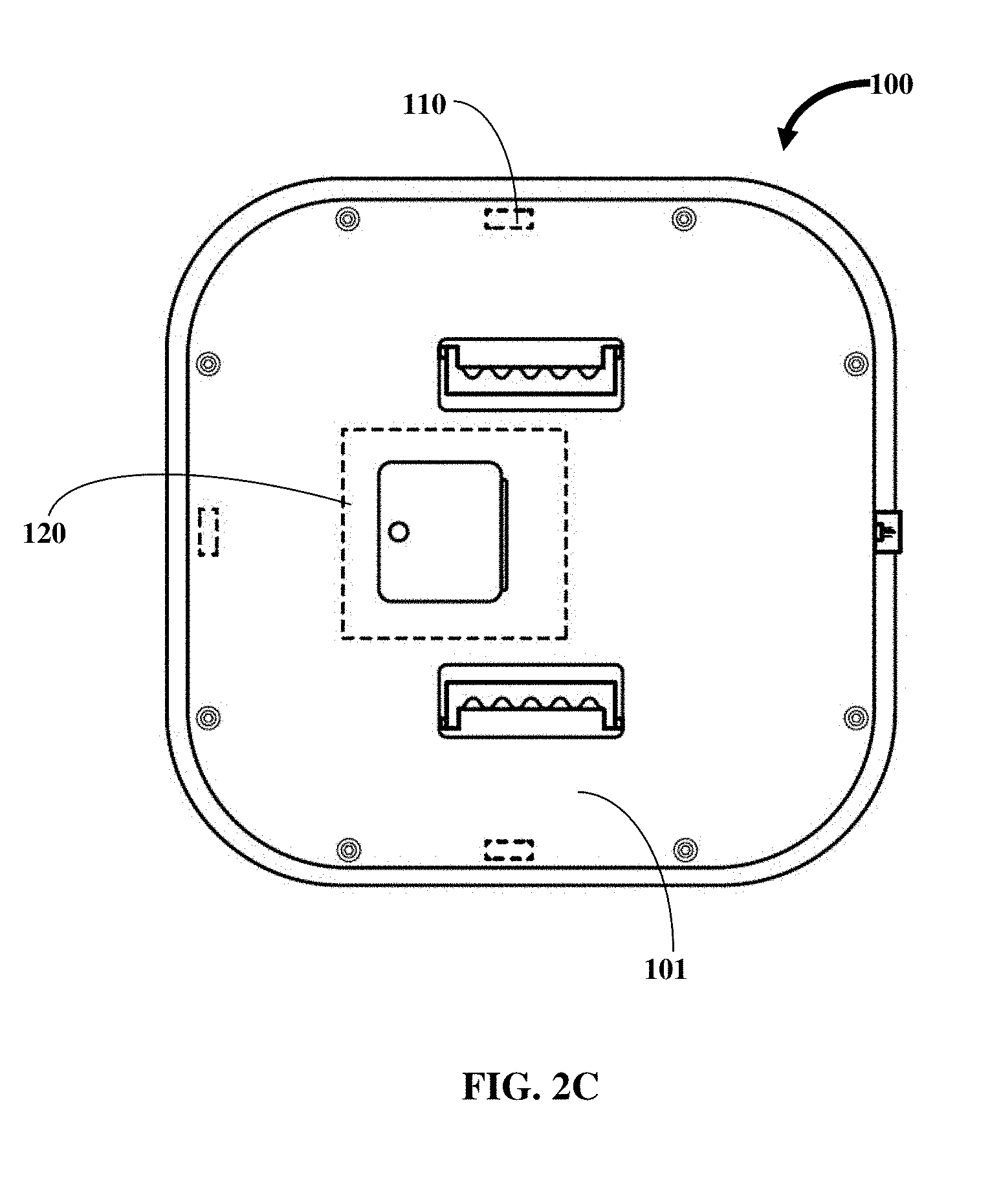
[0019] FIG. 2C exemplarily illustrates a top plan view of the vacuum cleaning device.
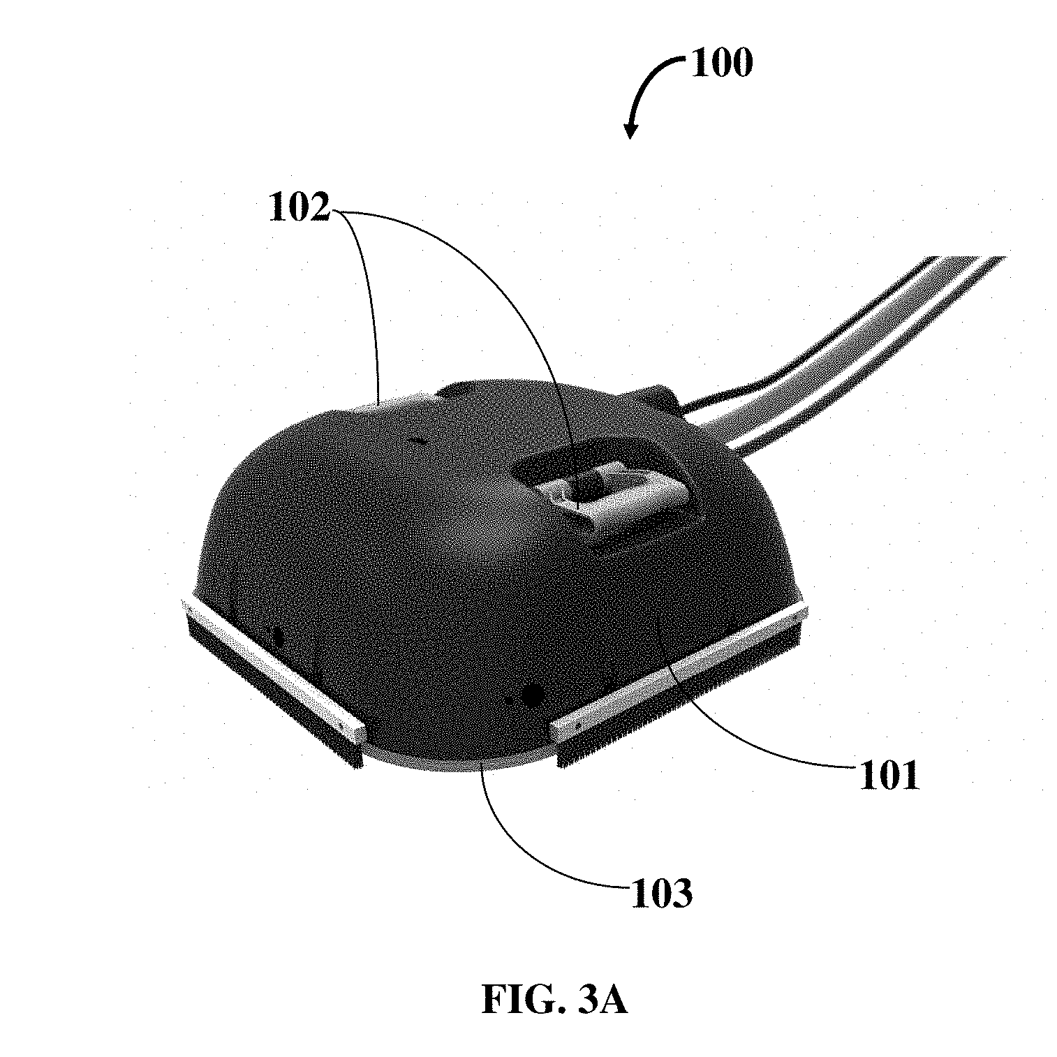
[0020] FIG. 3A exemplarily illustrates a top perspective view of the vacuum cleaning device.
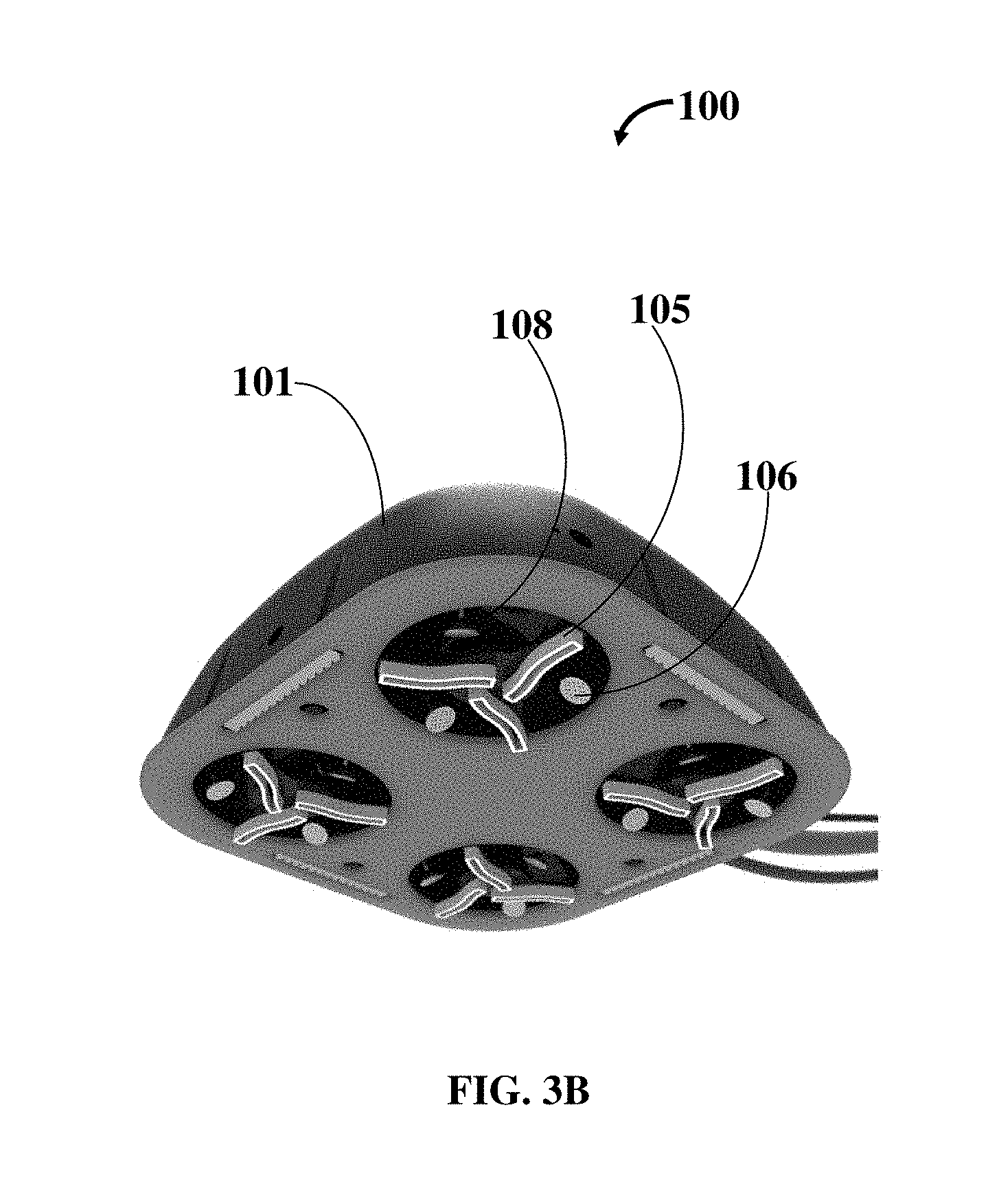
[0021] FIG. 3B exemplarily illustrates a bottom perspective view of the vacuum cleaning device.
[0022] The various aspects of the present disclosure mentioned above are described in further detail with reference to the aforementioned figures and the following detailed description of exemplary embodiments.
DETAILED DESCRIPTION
[0023] In the following detailed description, a reference is made to the accompanying drawings that form a part hereof, and in which the specific embodiments that may be practiced is shown by way of illustration. These embodiments are described in sufficient detail to enable those skilled in the art to practice the embodiments and it is to be understood that the logical, mechanical and other changes may be made without departing from the scope of the embodiments. The following detailed description is therefore not to be taken in a limiting sense.
[0024] Embodiments of the present invention are directed to a computer-implemented, self-controlling vacuum cleaning device, which is intended for operational deployment on soft cleaning surfaces, especially those that pertain to carpets, floor mats, rugs, and the like. The device is computer implemented to the point that it doesn't require manual intervention for its operation right from start to finish. More specifically, the device propels itself over the soft surface in a pattern that is determined by the device itself.
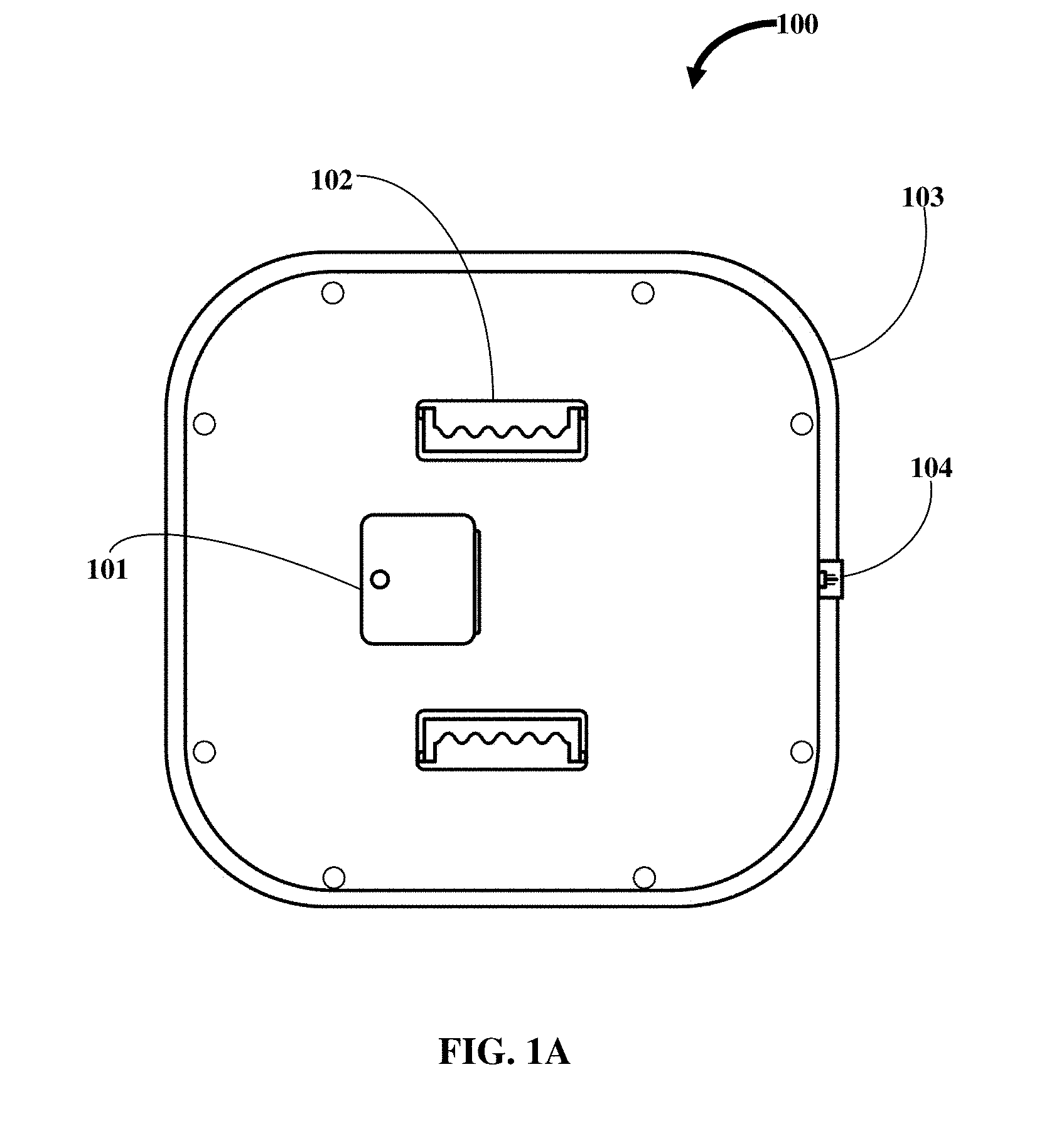
[0025] Referring to FIGS. 1A and 1D, the device 100 comprises a chassis and an outer shell sealingly fitted on top of the chassis wherein, almost every component of the device 100 is disposed between chassis and the outer shell. More particularly, the outer shell is secured to the chassis using eight-plated steel socket head cap screws. The device 100 is powered by a retractable power cord 104 residing therewithin wherein, the power cord 104 connects the device 100 to an electrical wall socket. The power cord 104 is wound around a spring-loaded spindle wherein, the power cord 104 is pulled out until it latches. Upon the completion of the usage of the device 100, the power cord 104, upon being manually pulled out slightly, activates the spindle. This causes the power cord 104 to wound back around the spindle. Notably, the power cord 104 comprises a 120 VAC power cord 104. In one embodiment, the power cord 104 is provided as an external umbilical, which is connected between the wall socket and a power cord connector 112 disposed at the rear of the outer shell.
[0026] In one embodiment, the power cord 104 comprises a 50', 12/2 with a 16 gauge ground. The male cord end is grounded and the copper stranded wires are individually insulated with PVC insulation and the 3 wires are contained in flexible PVC jacket. The power cord 104 is designed for years of use in portable machine operation. The power cord 104 is resistant against water, cleaning compound, and sunlight. The auto retractable spindle has an adjustable locking ratchet to secure the power cord 104 at the desired length. A small pull disengages the ratchet and the linear spring motor smoothly retracts the power cord 104. A cord guide lays the power cord uniformly so that, power cord never gets tangled on the spindle.
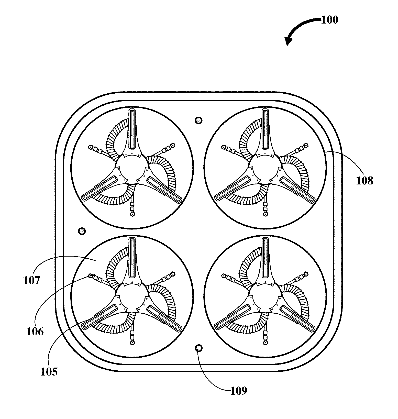
[0027] Referring to FIGS. 1B and 2B, the chassis is a flat, substantially rectangular member with the corners thereof being rounded. Four substantially circular holes disposed on the chassis extend from the top to the bottom surface thereof. More particularly, two holes (which hereinafter are referred to as front holes) are disposed closer to the front edge of the chassis, while the remaining two holes (which hereinafter are referred to as rear holes) are disposed closer to the rear edge of the chassis. Notably, the centers of the front and rear holes are laterally aligned and the pairs of front and rear holes closer to the side edges are longitudinally aligned. Each hole is adapted to receive a rotary cleaning head 108, which is pre-fitted within a bell-shaped casting (with stainless steel fasteners) that is preferably made of aluminum. The assembly between the bell-shaped casting and chassis is configured such that, upon the reception of a bell-shaped casting within a hole, the cleaning head 108 extends slightly beyond the bottom surface of the chassis. The plane of rotation of a cleaning head 108 is parallel the bottom surface of the chassis. The cleaning head 108 is driven by a brushless DC motor drive rotating head 119, which is in operative communication with a nonslip toothed belt. The cleaning head 108 driven by the toothed belt very quietly. The belts and pulleys employed have multiple years operating life so the DC motor drives are virtually maintenance free. The DC motor is powered by motor driver that is computer controlled. These brushless drive motors are very quiet, durable, maintenance free, and are geared down. The torque of the DC motor is instantaneous so the machine never gets bogged down, even on a shag carpet. While only one reduction is shown, a multi-stage system may have to be employed to get to a 25:1 reduction. Notably, the speed of rotation of each cleaning head 108 ranges from 0 to 130 RPM. The bell shaped shell protects the cleaning heads 108 and contains any debris that is kicked up by the cleaning heads 108.
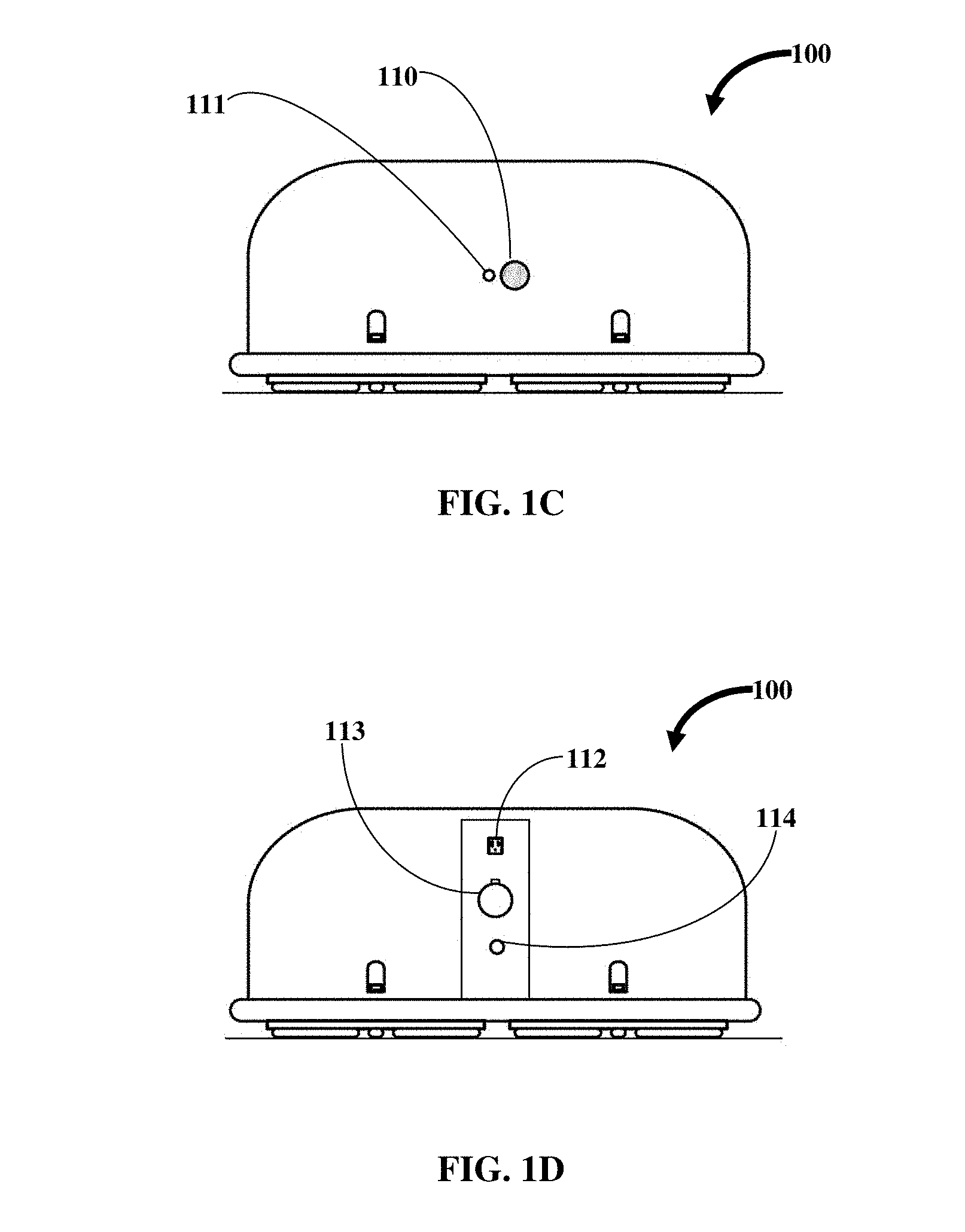
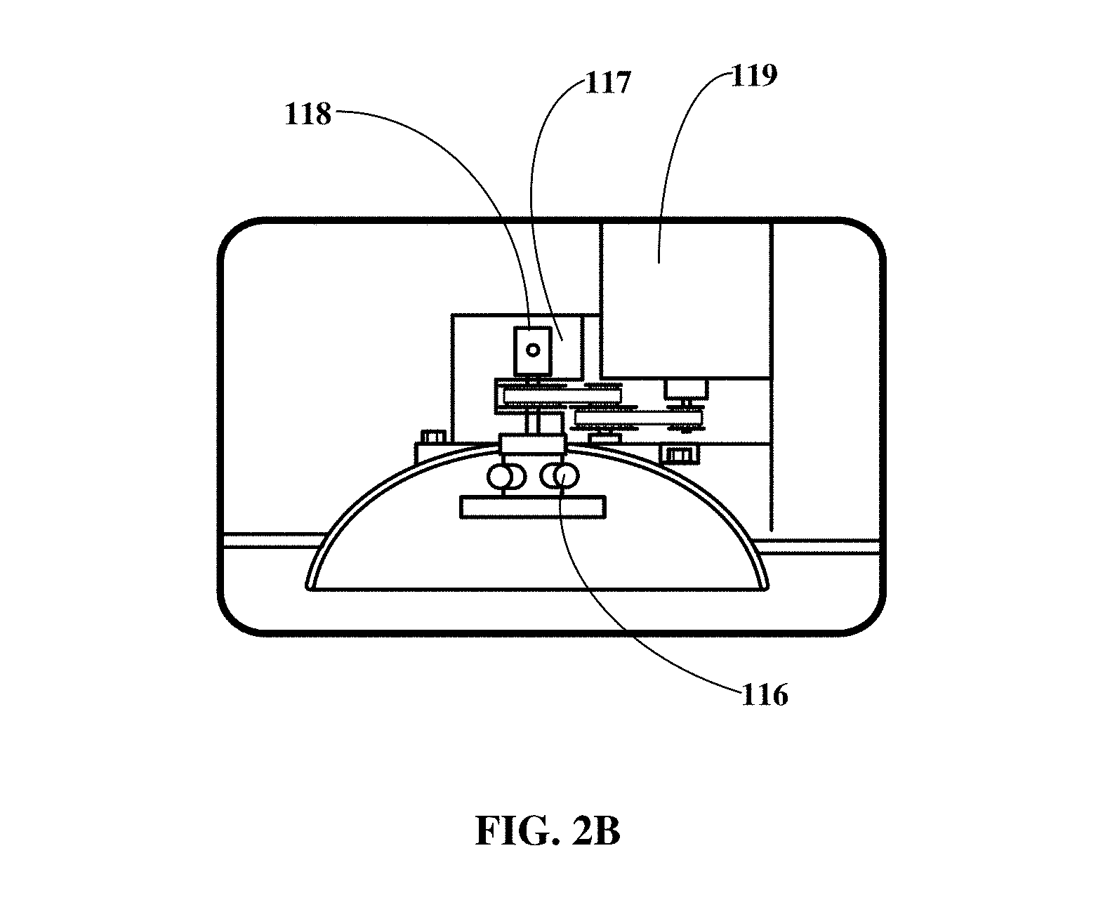
[0028] Referring to FIGS. 1B, 1D, 2A and 3B, the cleaning head 108 comprises a three suction heads 105 extending radially from the center (of the cleaning head 108) such that, the angle between two successive cleaning heads 108 is equivalent (i.e., 60.degree.). As viewed from bottom, each suction head 105 is elongated and substantially rectangular with a central, substantially rectangular opening through which, dirt is suctioned during the operation of the device 100. Notably, the mid portion of the suction head 105 (as viewed from bottom) is slightly curved. Each suction head 105 is spring loaded in that the suction head 105, upon of release of an upward push applied thereto, returns downwardly to the original position thereof. Notably, the leading and trailing edges of the cleaning heads 108 are rounded for providing a smooth compressing cleaning surface. The suction heads 105 are disposed in fluid communication with a suction chamber 117 via a vacuum hose 116. Notably, the suction chamber 117 is a part of the cleaning head 108 and therefore, resides within the corresponding bell-shaped casting. Each suction chamber 117 is in turn disposed in fluid communication with a plenum via another vacuum hose 116. An external vacuum hose removably accessing the plenum from the rear of the device 100 (via a vacuum hose connector 113) facilitates the discharge of the dirt collected over time within the plenum. In one embodiment, the device 100 comprises a large vacuum plenum. The large vacuum plenum is permanent molded from aluminum and the bottom half is mounted to the hinged door 101. The forward upper half thereof is removable for easy cleaning in case some maintenance is required after many operating cycles of the device 100. The vacuum is maintained by an O-ring being compressed between the two sections, with pressure being applied using two plastic knobbed bolts. The high capacity AC to DC converter sits under the power cord spindle and on top of the rear part of the plenum, using the large aluminum structure as the heat sink.
[0029] Referring to FIGS. 1B, 1D, 2A and 2B, the cleaning head 108 further comprises three spray heads 106, each of which disposed between two successive suction heads 105. Notably, the angle between two successive spray heads 106 with respect to the center is equivalent (i.e., 60.degree.). The spray heads 106 are configured to discharge pressurized cleaning solution therefrom. More particularly, three threaded holes are disposed in a fiber-glass reinforced centre hub 107 (fitted within the bell-shaped casting) that allow attachment of the spray head piping and the spray head 106 thereto. The piping is fabricated, for example, using 3/8-NPT brass pipe and the various fittings to allow the spray head 106 to be directed downward toward the cleaning surface ahead of the suction head 105. The cleaning solution is supplied from an external source via an external solution hose 114 connecting said source and the rear of the outer shell. The solution is supplied to the spray heads by a self-supporting rotating union 118. The rotating union 118, as enabled by a DC solenoid, allocates the solution to the four cleaning heads 108. The device 100 is operationally configured such that, first, the solution is discharged from the spray heads 106 (in a conical spray pattern) whereafter, the solution mixed with the dirt is suctioned by the suction heads 105. Notably, the suction and spray heads 105 and 106 are mounted on a fiberglass-reinforced center hub 107.
[0030] Referring to FIG. 1C, the device 100 further comprises three distance sensors 110 viz., a front and two side distance sensors 110. The front distance sensor 110 is mounted at the front of the device 100, while the side distance sensors 110 are mounted at the sides of the device 100. More particularly, the distance sensors 110 are mounted on the outer shell. Each distance sensor 110 is for calculating the distance between the device 100 and an obstacle in the line of sight thereof. The obstacle could be a wall or any object that blocking the vision of the sensor. The distance sensor 110 comprises an LED 111 of preferably red color. During the operation, the distance sensors 110 emit a beam of light and then determine room sizes up to 130 feet in each direction. The distance sensors 110 are engaged during the cleaning operation and measure the machine location within the room to within .+-.0.1 inches. In an embodiment, the vacuum cleaning device 100 further comprises an optional vision system, which is added if the device 100 is be used within a furniture filled room.
[0031] Referring to FIGS. 2C, 3A and 3B, the device 100 further comprises a computer controller for controlling the operation thereof. The computer controller comprises a user interface for enabling a user to interact therewith. More particularly, the user interface comprises a touchscreen 120 disposed on top of the outer shell. The touchscreen 120 is covered by a hinged door 101 for protection. The hinged door is water jet machined using, for example, 6061 aluminum alloy sheet. After fabrication, the appropriate holes are tapped on a CNC milling center, the hinged door 101 is cleaned, anodized, dyed a matching, complementary, or contrasting color to that used for the protective housing. The anodize coating prevents oxidation of the aluminum and provides a scratch resistant surface, greatly reducing wear during use. The computer controller further comprises a mapping and a motion module, the utility of each of which will become apparent from the following body of text. Upon the device 100 being placed on a cleaning surface and powered on via the user interface, the computer controller is configured to initially measure the distance between the device 100 and the obstacles that lay ahead and sideways. The distance sensors 110 are disposed in operational conjunction with the mapping sensor whereby, the mapping module, based on the calculations obtained from the distance sensors 110, virtually creates a cleaning pattern on the cleaning surface. The motion module, as enabled by the rotary motion of the cleaning heads 108, propels the device 100 in the cleaning pattern. Along the cleaning pattern on the cleaning surface, the cleaning solution is sprayed thereon and consecutively worked thereinto. More particularly, the stainless steel cleaning heads 108 glide on the dampened cleaning surface and slightly compress the fibers thereof to work the cleaning solution in and the suction heads 105 remove the dirty solution. Once the cleaning solution is worked in, the emerging solution mixed with impurities are suctioned by the suction heads 105, which is then transferred into the suction chambers 117 and ultimately into the common plenum.
[0032] Referring to FIGS. 1B and 3B, the device 100 further comprises a plurality of downwardly facing stain sensors 109 disposed on bottom surface of the chassis. The stain sensors 109, as the name suggests, are employed for detecting stains on the cleaning surface. Each stain sensor 109 comprises a light source for emitting a monochromatic light source onto the cleaning surface. A CCD camera employed by the stain sensor 109 simultaneously captures the monochromatic light that is reflected off the cleaning surface. A stain module, which is a part of the computer controller, analyzes said returned light by comparing the same against the previous samples of returned light. In the event of disparity between the returned light and the previous samples beyond a predetermined threshold, the site on the cleaning surface wherefrom the returned light is captured is deemed a stain site. Upon detection of a stain site in the aforementioned fashion, the computer controller is configured to propel the device 100 back to the stain site and stay the device 100 thereon for a longer time. The stain sensors 109 also detect any open space beneath the device 100 and thereby prevent the device 100 from falling thereinto. For example, the stain sensors 109 prevent the device 100 from falling down a flight of stairs.
[0033] In an additional embodiment, the device 100 is configured to be operated manually. More particularly, in this "manual mode" embodiment, the user is allowed by the computer controller to override the mapping and motion modules as the user, via his/her connected smartphone, navigates/maneuvers the device 100 in whatever pattern he/she decides fit. Notably, the smartphone is connected to the device 100 via Bluetooth, Wi-fi, or the like. Selecting an exemplary "manual mode" button on the touchscreen 120 activates the manual mode, which simultaneously suspends the self-controlling aspect of the device 100, which is enabled by the computer controller modules.
[0034] Referring to FIGS. 2A, 2C, 3A and 3B, the device 100 further comprises a pair of handles 102 that are hingedly secured within the pockets carved on top of the outer shell. As the outer shell is preferably made of molded plastic, it is strong enough to allow the device 100, which weighs about 50 pounds, to be picked up and carried about the handles 102. More particularly, the outer shell is made from blow-molded polypropylene plastic. The outer shell is thick plastic and is very durable, highly resistant to household and cleaning chemicals, and is highly resistant to blows and scrapes. The outer shell can be supplied in almost any vibrant color, so a distinctive color may be chosen to enhance the product recognition factor, which can dramatically improve the market adoption of the device 100. The handles 102 are adapted to be angularly movable between a rest position and a carry position. Notably, at rest position, the handles 102 are disposed parallel to the top, substantially flat surface of the outer shell whereas, at the carry position, the handles 102 are perpendicular to the top surface of the outer shell. Notably, the handles 102 are a product of an injection molding process.
[0035] Referring to FIGS. 2A, 2C, 3A and 3B, the sides of the device 100 are lined with a non-marring bumper so as to prevent any damage thereto in the event of inadvertent collisions. Preferably, the bumper is made of polyurethane rubber. Notably, the chassis comprises a polarized, locking connector 115 disposed on the top surface and closer to the front edge thereof. The polarized connector 115 is adapted to receive a matching insert thereinto wherein, the insert is disposed on the outer shell. The insertion of the insert into the polarized connector 115 establishes an electrical communication between the components mounted on the outer shell and on the chassis as enabled by the wiring harness. The harness employs PVC insulated stranded copper wires that are bundled in a 10 mil thick polyethylene braid protective shield. This allows the connecting wires of the device 100 to be pulled through a sidewall and yet the balance of wires remain covered, enhancing the look of the harness and eliminating most of the tie wraps in typical harness assembly. The specially designed polarized connector allows the chassis to be connected to the computer controller and various drivers in the outer shell. There is some additional harness length within the outer shell that allows it to be removed and turned upside down in front of the device 100 to allow preventative maintenance. In an additional embodiment, to augment the cleaning head's mobility capability, the device 100 can be equipped with individually controlled drive wheels and a front mounted caster.
[0036] In an embodiment, the computer controller is a small outline unit that is a disposed within a ruggedized, splash proof case and comprises a full color touch screen display 120 facing upward behind the hinged door 101 in the outer shell. A special computer software program is written to operate the device 100 and can be upgraded in the field using the Bluetooth connection. The high current drivers and motor controllers are mounted on a separate but nearby printed circuit board (PCB).
[0037] The foregoing description of the specific embodiments will so fully reveal the general nature of the embodiments herein that others can, by applying current knowledge, readily modify and/or adapt for various applications such specific embodiments without departing from the generic concept, and, therefore, such adaptations and modifications should and are intended to be comprehended within the meaning and range of equivalents of the disclosed embodiments. It is to be understood that the phraseology or terminology employed herein is for the purpose of description and not of limitation. Therefore, while the embodiments herein have been described in terms of preferred embodiments, those skilled in the art will recognize that the embodiments herein can be practiced with modification within the spirit and scope of the appended claims.
* * * * *
D00000
D00001
D00002
D00003
D00004
D00005
D00006
D00007
D00008
XML
uspto.report is an independent third-party trademark research tool that is not affiliated, endorsed, or sponsored by the United States Patent and Trademark Office (USPTO) or any other governmental organization. The information provided by uspto.report is based on publicly available data at the time of writing and is intended for informational purposes only.
While we strive to provide accurate and up-to-date information, we do not guarantee the accuracy, completeness, reliability, or suitability of the information displayed on this site. The use of this site is at your own risk. Any reliance you place on such information is therefore strictly at your own risk.
All official trademark data, including owner information, should be verified by visiting the official USPTO website at www.uspto.gov. This site is not intended to replace professional legal advice and should not be used as a substitute for consulting with a legal professional who is knowledgeable about trademark law.