Merchandising Display Having Quick Shelf Set Up
Nixon; Matthew A. ; et al.
U.S. patent application number 16/035210 was filed with the patent office on 2019-01-17 for merchandising display having quick shelf set up. The applicant listed for this patent is Mid-Atlantic Packaging & Specialties, Inc.. Invention is credited to Jonathan M. Genord, Matthew A. Nixon.
| Application Number | 20190014927 16/035210 |
| Document ID | / |
| Family ID | 65000736 |
| Filed Date | 2019-01-17 |


View All Diagrams
| United States Patent Application | 20190014927 |
| Kind Code | A1 |
| Nixon; Matthew A. ; et al. | January 17, 2019 |
MERCHANDISING DISPLAY HAVING QUICK SHELF SET UP
Abstract
A merchandising display capable of being assembled from a knockdown form, and which has one or more shelves that can be quickly folded and secured into position.
| Inventors: | Nixon; Matthew A.; (Bangor, PA) ; Genord; Jonathan M.; (Lansdale, PA) | ||||||||||
| Applicant: |
|
||||||||||
|---|---|---|---|---|---|---|---|---|---|---|---|
| Family ID: | 65000736 | ||||||||||
| Appl. No.: | 16/035210 | ||||||||||
| Filed: | July 13, 2018 |
Related U.S. Patent Documents
| Application Number | Filing Date | Patent Number | ||
|---|---|---|---|---|
| 62531979 | Jul 13, 2017 | |||
| Current U.S. Class: | 1/1 |
| Current CPC Class: | A47B 47/06 20130101; B65D 5/52 20130101; B65D 5/5213 20130101; A47B 43/02 20130101; A47F 5/0018 20130101; B65D 5/5206 20130101; A47B 55/06 20130101; A47F 5/116 20130101 |
| International Class: | A47F 5/11 20060101 A47F005/11; A47B 43/02 20060101 A47B043/02; A47B 47/06 20060101 A47B047/06; A47B 55/06 20060101 A47B055/06; B65D 5/52 20060101 B65D005/52; A47F 5/00 20060101 A47F005/00 |
Claims
1. A display that can be assembled from a knockdown form, comprising: a front wall panel; a back wall panel opposing said front wall panel; a first side wall panel attached to and extending between said front and back wall panels, said first side wall panel comprising first and second side wall sections separated from one another along a fold line extending longitudinally therebetween, and said first side wall panel includes an opening therein having an edge; a second side wall panel opposing said first side wall panel and attached to and extending between said front and back wall panels, said second side wall panel comprising first and second side wall sections separated from one another along a fold line extending longitudinally therebetween; each of said first and second side wall sections of said first side wall panel has a face, said first and second side wall sections of said first side wall panel being folded about said fold line therebetween when the display is in the knockdown form such that said face of said first side wall section and said face of said second side wall section are in face to face relation with one another, said first and second side wall sections of said first side wall panel being foldable about said fold line therebetween such that said face of said first side wall section and said face of said second side wall section move out of face to face relation when the display is assembled from the knockdown form; and a first shelf section formed in said front wall panel and integrally attached thereto at an end of said first shelf section, said first shelf section being foldable along said end into an interior of said display to a position supported by said edge of said opening in said first side wall panel when the display is assembled from the knockdown form.
2. A display in accordance with claim 1 wherein said front and back wall panels are in face to face relation with one another in the knockdown form and are separated from one another when assembled into the display.
3. A display in accordance with claim 2 wherein each said face of said first and second side wall sections of said first side wall panel is an inner face, and wherein said inner face of said first side wall section and said inner face of said second side wall section are in face to face relation when the display is in the knockdown form such that said first and second side wall sections extend away from said front and back wall panels.
4. A display in accordance with claim 2 wherein each said face of said first and second side wall sections of said first side wall panel is an outer face, and wherein said outer face of said first side wall section and said outer face of said second side wall section are in face to face relation when the display is in the knockdown form such that said first and second side wall sections extend inwardly so as to be sandwiched between said front and back wall panels.
5. A display in accordance with claim 1 wherein each of said first and second side wall sections of said second side wall panel has a face, said first and second side wall sections of said second side wall panel being folded about said fold line therebetween when the display is in the knockdown form such that said face of said first side wall section of said second side wall panel and said face of said second side wall section of said second side wall panel are in face to face relation with one another, said first and second side wall sections of said second side wall panel being foldable about said fold line therebetween such that said face of said first side wall section of said second side wall panel and said face of said second side wall section of said second side wall panel move out of face to face relation when the display is assembled from the knockdown form.
6. A display in accordance with claim 1 further comprising a second shelf section formed in said back wall panel and integrally attached thereto at an end of said second shelf section, said second shelf section being foldable along said end of said second shelf section into said interior of said display to a position supported by said edge of said opening in said first side wall panel when the display is assembled from the knockdown form.
7. A display in accordance with claim 6 wherein said first and second shelf sections are adjacent to and coplanar to one another in the assembled display.
8. A display in accordance with claim 6 wherein said first and second shelf sections are parallel to one another in face to face relation when in the knockdown form.
9. A display in accordance with claim 7 wherein said first and second shelf sections are parallel to one another in face to face relation when in the knockdown.
10. A display in accordance with claim 1 wherein said opening in said first side wall panel comprises openings is said first and second side wall sections of said first side wall panel.
11. A display in accordance with claim 10 wherein said openings in said first and second side wall sections of said first side wall panel form a single opening.
12. A display in accordance with claim 1 further comprising a second shelf section formed in said front wall panel and integrally attached thereto at an end of said second shelf section, said second shelf section being foldable along said end of said second shelf section into said interior of said display to a position supported by an edge of a second opening in said first side wall panel when the display is assembled from the knockdown form.
13. A display in accordance with claim 1 further comprising at least one tab along said end of said first shelf section extending upwardly for maintaining product on said shelf section.
14. A display that can be assembled from a knockdown form, comprising: a front wall panel; a back wall panel; a first side wall panel attached to and extending between said front and back wall panels, said first side wall panel comprising first and second side wall sections separated from one another along a fold line extending longitudinally therebetween; a second side wall panel opposing said first side wall panel and attached to and extending between said front and back wall panels, said second side wall panel comprising first and second side wall sections separated from one another along a fold line extending longitudinally therebetween; each of said first and second side wall sections of said first side wall panel has a face, said first and second side wall sections of said first side wall panel being foldable about said fold line between the knockdown form in which said face of said first side wall panel section and said face of said second side wall section are in face to face relation with one another, and the assembled display in which said face of said first side wall section and said face of said second side wall section are not in face to face relation with one another; and a first shelf section formed in said front wall panel and attached thereto at an end of said first shelf section, said first shelf section being foldable along said end into an interior of said display to a position supported by said first side wall panel when the display is assembled from the knockdown form.
15. A display in accordance with claim 14 wherein said front and back wall panels are in face to face relation with one another in the knockdown form and which are separated from one another when assembled into the display.
16. A display in accordance with claim 14 wherein each said face of said first and second side wall sections of said first side wall panel is an inner face, and wherein said inner face of said first side wall section and said inner face of said second side wall section are in face to face relation with one another when the display is in the knockdown form such that said first and second side wall sections extend away from said front and back wall panels.
17. A display in accordance with claim 14 wherein each said face of said first and second side wall sections of said first side wall panel is an outer face, and wherein said outer face of said first side wall section and said outer face of said second side wall section are in face to face relation with one another when the display is in the knockdown form such that said first and second side wall sections extend inwardly so as to be sandwiched between said front and back wall panels.
18. A display in accordance with claim 15 wherein said display is formed from a unitary sheet of corrugated paperboard.
19. A display in accordance with claim 14 wherein said first side wall panel includes an opening therein having a lower edge, and said first shelf section being supported by said lower edge when assembled into the display.
20. A display in accordance with claim 14 further comprising at least one tab along said end of said first shelf section extending upwardly for maintaining product on said shelf section.
21. A display in accordance with claim 16 wherein each of said first and second side wall sections of said second side wall panel has an inner face, and wherein said inner face of said first side wall section of said second side wall panel and said inner face of said second side wall section of said second side wall panel are in face to face relation with one another when the display is in the knockdown form such that said first and second side wall sections of said second side wall panel extend away from said front and back wall panels.
22. A display in accordance with claim 17 wherein each of said first and second side wall sections of said second side wall panel has an outer face, and wherein said outer face of said first side wall section of said second side wall panel and said outer face of said second side wall section of said second side wall panel are in face to face relation with one another when the display is in the knockdown form such that said first and second side wall sections of said second side wall panel extend inwardly so as to be sandwiched between said front and back wall panels.
Description
CROSS-REFERENCE TO RELATED APPLICATIONS
[0001] This application claims the benefit of U.S. Provisional Application No. 62/531,979 filed Jul. 13, 2017, and which is hereby incorporated herein by reference in its entirety.
FIELD OF THE INVENTION
[0002] The present invention pertains to merchandising displays used for displaying products available for sale in a retail setting. More particularly, the invention relates to such displays that can be assembled at the retail site.
DESCRIPTION OF THE RELATED ART
[0003] Merchandising displays can be found in retail stores and are used to display goods for sale. Such displays typically have shelves for holding the goods, a classic use being for food items such as bags of potato chips, pretzels or other such items. The displays can be free standing on the floor, or counter and shelf displays. One such type of merchandising display is known in the industry as a point of purchase or "POP" display. Merchandising displays can include artwork and advertising print thereon to provide a pleasing and informative display.
[0004] Merchandising displays are typically made of corrugated paperboard and shipped in a flat form to the retailer. They are assembled at the retailer and goods for sale are placed on it for display.
[0005] Current known freestanding displays can be complicated to set up, and use an excessive amount of corrugated paperboard. One known merchandising display configuration, known as a hutch style display, has six wall panels to be folded for assembly at the retail site. The setup process is complicated and time-consuming. Moreover, the added materials add undesired costs.
[0006] Accordingly, an improved merchandising display that is less complicated, less costly, and easier to set up is highly desirable.
SUMMARY OF THE INVENTION
[0007] The present invention provides a merchandising display that can be assembled from a knockdown form. In one form, the display includes a front wall panel; a back wall panel, and first and second side wall panels attached to and extending between the front and back wall panels. Each of the first and second side wall panels includes first and second side wall sections separated from one another along a fold line extending longitudinally between them.
[0008] Each of the first and second side wall sections of the first side wall panel has a face. The first and second side wall sections of the first side wall panel is foldable about its fold line between the knockdown form in which the face of the first side wall panel section and the face of said second side wall section are in face to face relation with one another, and the assembled display form in which the face of the first side wall section and the face of said second side wall section are not in face to face relation with one another. The display further includes a first shelf section formed in the front wall panel and attached thereto at an end of the first shelf section. The first shelf section is foldable along its end into an interior of the display to a position supported by the first side wall panel when the display is assembled from the knockdown form.
[0009] Addition features and embodiments are described below.
BRIEF DESCRIPTION OF THE DRAWINGS
[0010] The foregoing summary, as well as the following detailed description, will be better understood when read in conjunction with the accompanying drawings. For illustrating the invention, there are shown in the drawings several preferred embodiments. It is understood, however, that this invention is not limited to these embodiments, and is to be limited only by the appended claims.
[0011] FIG. 1 is a perspective view of a fully assembled freestanding merchandising display in accordance with the present invention;
[0012] FIG. 2 is a blank from which the merchandising display shown in FIG. 1 can be assembled;
[0013] FIGS. 3-4 are perspective views showing the steps for forming a knockdown from the blank shown in FIG. 2;
[0014] FIG. 5 is a knockdown (KDF) formed from the blank shown in FIG. 2;
[0015] FIGS. 6-7 are perspective views showing steps for forming a bellows form from the knockdown shown in FIG. 5;
[0016] FIG. 8 is a top view of a bellows form made from the knockdown shown in FIG. 5;
[0017] FIGS. 9-19 are perspective views showing the steps for forming the assembled merchandising display shown in FIG. 1; and
[0018] FIG. 20 is a perspective view of two merchandising displays of the type shown in FIG. 1 with one stacked on top of the other.
DETAILED DESCRIPTION
[0019] The invention disclosed herein provides a novel merchandising display, and a container knockdown assembly and blank therefore. Described below are illustrative embodiments of the invention. It is understood, however, that the present invention is not so limited and can be adapted to other merchandising displays.
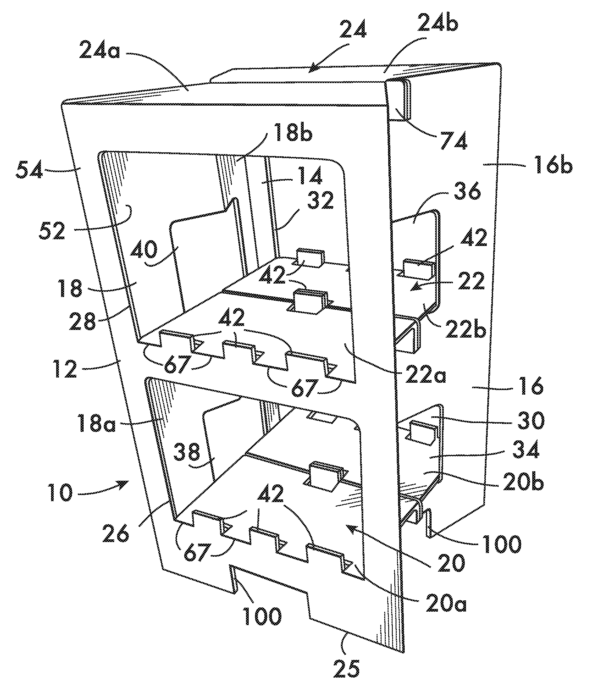
[0020] With initial reference to FIG. 1, a merchandising floor stand style display 10 is shown fully assembled standing on the floor. The merchandising display 10 includes a front wall panel 12, a back wall panel 14 opposite the front wall panel 12, and first and second side wall panels 16, 18 opposite one another and each one attached to and extending between the front and back wall panels 12 and 14. The display 10 further includes a lower shelf 20, upper shelf 22, and top 24, and a bottom edge 25 sitting on the floor. Front openings 26, 28, in the front wall panel 12, and back openings 30, 32 in the back wall panel 14, allow easy access for the consumer to the goods on the shelves 20, 22. Lower and upper side openings 34, 36, and 38 and 40 in opposing side wall panels 16, 18 as shown are provided for aiding in the support of the shelves 22, 24 as further described below, and add to the visibility of the goods within. The illustrated embodiment is ideally suitable for goods such as bags of potato chips, pretzels and other similar products that would fit well on the shelves 20, 22. Tabs 42 provided at the front and back of the shelves 20, 22 help prevent the products from sliding off the shelves 20, 22.
[0021] The display 10 is made preferably from corrugated paperboard such as B flute although any suitable materials can be used. As further described below, the merchandising, display 10 is formed preferably from a single integral sheet of corrugated material.
[0022] Having described the general features of the merchandising display 10 in a fully assembled form, the manufacture, assembly, and use thereof is now described. The manufacture and assembly of the merchandising display 10 begins preferably with the manufacture of a blank 50 in flat form, as illustrated in FIG. 2. The blank 50 is preferably die cut from a unitary sheet of corrugated paperboard and includes all the panel sections and flaps to form the merchandising display 10. The blank 50, with its various panels and flaps, has two faces 48 that are major surfaces on opposite sides of the blank 50, these being an inner face 52 and an outer face 54 opposite to the inner face 52 and on the underside not shown in this view. As customary in the industry with specification drawings showing the blank 50, the view in FIG. 2 shows the inner face 52 (see FIGS. 1 and 6 showing outer face 54, which in the preferred embodiment, has a white printable surface).
[0023] The various panels and flaps are delineated from one another along fold lines 56, some of which are formed preferably by scores 56a in the corrugated paperboard and others formed preferably by perforations 56b. Any suitable fold line configuration providing a suitable line of weakness to aid in folding may be used.
[0024] The blank 50 includes the various panels and flaps of the display 10, which include the front wall panel 12, back wall panel 14, and side wall panels 16, 18. Side wall panel 16 is divided into two side wall sections 16a and 16b separated from one another along a fold line 56b at 60 extending longitudinally between the top and bottom of the side wall panel 16. Side wall panel 18 is divided into two side wall sections 18a and 18b separated from one another along a fold line 56b at 62 extending longitudinally between the top and bottom of the side wall panel 18. Top panels 24a and 24b, which extend from the top end of respective front and back wall panels 12, 14 along a fold line 56a as shown, will ultimately form the top 24. A glue tab 58 is connected to a side end of the side wall panel 18 along a scored fold line 56a as shown.
[0025] Cutouts 64 in the respective side wall panels 16, 18, form the side openings 34, 36, 38 and 40. These side openings extend on either side of the fold lines 56b at 60 and 62 as shown, and include edges 44 bounding the side openings 34, 36, 38 and 40. Slots 46 are cut into the blank 50 for purposes described below. In the illustrated embodiment, the side openings 34, 36, 38 and 40 are each formed as a single opening, although other configurations can be used, e.g., the side opening 34 in side wall panel 16 could be formed as a first opening in the side wall section 16a and a second opening in the side wall section 16b separated from one another by a section of the side wall panel 16.
[0026] Each of the shelves 20 and 22 are formed preferably by two shelf sections. In the illustrated embodiment, shelf 20 is formed by a shelf section 20a attached to front wall panel 12, and shelf section 20b attached to back wall panel 14. Each of the shelf sections 20a, 20b, are formed from respective wall panels 12 and 14 by cut lines 66 and attached thereto along a bottom end of the shelf 67 at three fold lines 56a along a bottom end of the shelf 67 extending between the lower tabs 42 as shown. It is further seen that cutouts 68 and cuts 66 delineate the tabs 42 from the shelf sections 20a, 20b. It is further seen that the upper or back end of the shelf sections 20a, 20b include a connection tab 70 delineated from the remainder of their respective shelf panels 20a, 20b along scored fold lines 56a, there being at least one tab 42 formed along the connection tab 70 by cuts 66 and cutouts 68. Above each of the connector tabs 70 is a cutout 66 as shown, and two small slots 72 are provided for connecting the shelf sections 20a, 20b to the side wall panels 16 and 18 as described below during assembly of the merchandising display 10. Similarly, upper shelf 22 is formed by a shelf section 22a attached to front wall panel 12, and a shelf section 22b attached to back wall panel 14, and each include similar features as discussed above for shelf panels 20a, 20b.
[0027] It is further seen that each of the top forming panel sections 24a, 24b also include connector tabs 74 attached at the top of their respective top panels 24a, 24b along scored fold lines 56a. These connector tabs 74, similar to the connector tabs 70, also include slots 72 used for connecting the top panels 24a, 24b to respective side wall panels 16 and 18 during assembly as described below. The side openings 34, 36, 38 and 40 in the first and second side wall panels 16, 18 are formed by cutouts 68 as shown, and defined by edges 44 bounding the openings 34, 36, 38 and 40.
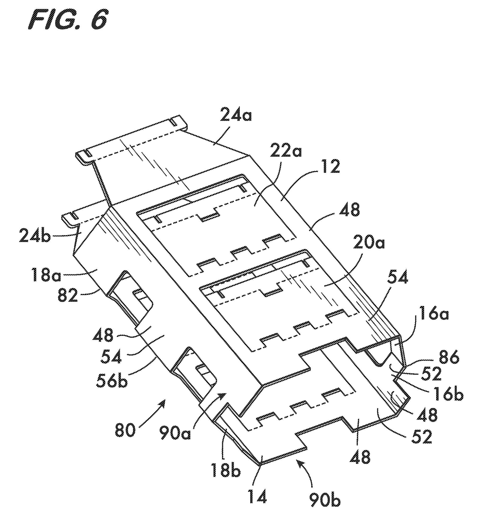
[0028] The blank 50 can be folded into a knockdown form 80 ("KDF") (see FIG. 5) which can be assembled into the final container assembly 10 as shown in FIG. 1. The assembly of the KDF 80 from the blank 50 is now described with further reference to FIGS. 2 to 8. With initial reference to FIGS. 2 and 3, the side wall section 18a with glue tab 58 is folded as a substantially flat unit about the fold line 56b along corner 82 to position the inner face 52 of side wall section 18a onto the inner face 52 of side wall section 18b to form the assembly shown in FIG. 3.
[0029] An adhesive 84, such as a hot melt glue, is applied preferably to the outer face 54 of the glue tab 58 (illustrated with shading in FIGS. 3 and 4). With the adhesive 84 in place, the side wall section 16a together with front wall panel 12 is folded as a substantially flat unit about the fold line 56b along corner 86 (see arrows 88) to position the inner face 52 of the edge area 76 of the wall panel 12 onto the outer face 54 of the glue tab 58, contacting the adhesive 84, to form the KDF 80 shown in FIG. 5.
[0030] The above-described process can be carried out automatically with modern machinery, the folds and adhesive application being completed thereby. This forms the KDF 80 having two substantially flat knockdown sections 90a, 90b (section 90b being disposed underneath 90a as seen in FIGS. 5 and 6) substantially parallel to one another and connected at the two opposing corners 82 and 86. As seen in FIG. 5, two of the major surfaces 48 of the two knockdown sections 90a, 90b are in face-to-face relation to one another, i.e., the inner faces 52 of the two knockdown sections 90a, 90b are in face-to-face relation to one another. The shelf sections 20a and 20b are seen in line with their respective wall panels 12 and 14 respectively and are parallel to one another. More specifically, the inner faces 52 of the front and back wall panels 12, 14 are in face to face relation as shown, the front and back side wall sections 16a, 16b of the first side wall panel 16 are folded about corner 82 and the inner faces 52 thereof are in face to face relation, and the front and back side wall sections 18a, 18b of the second side wall panel 18 are folded about corner 86 and the inner faces 52 thereof are in face to face relation. In this form the first the front and back side wall sections 16a, 16b of the first side wall panel 16 and the front and back side wall sections 18a, 18b of the second side wall panel 18 extend away from the front and back wall panels 12, 14 as shown, which can present a fairly wide configuration. The KDF 80 can be stacked with others for storage and shipping, but further shrinkage of the width dimension of the KDF 80 is possible as described below.
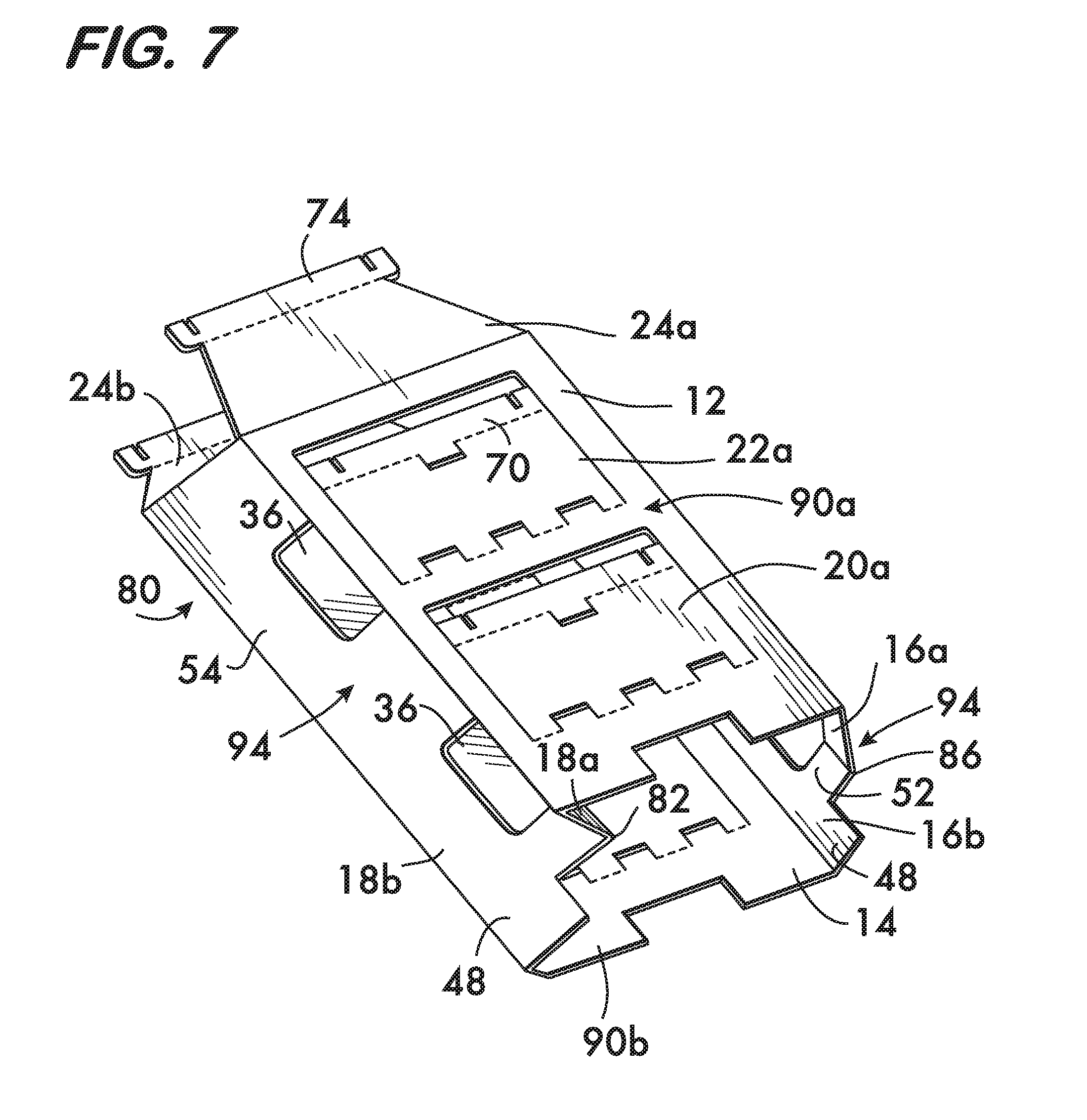
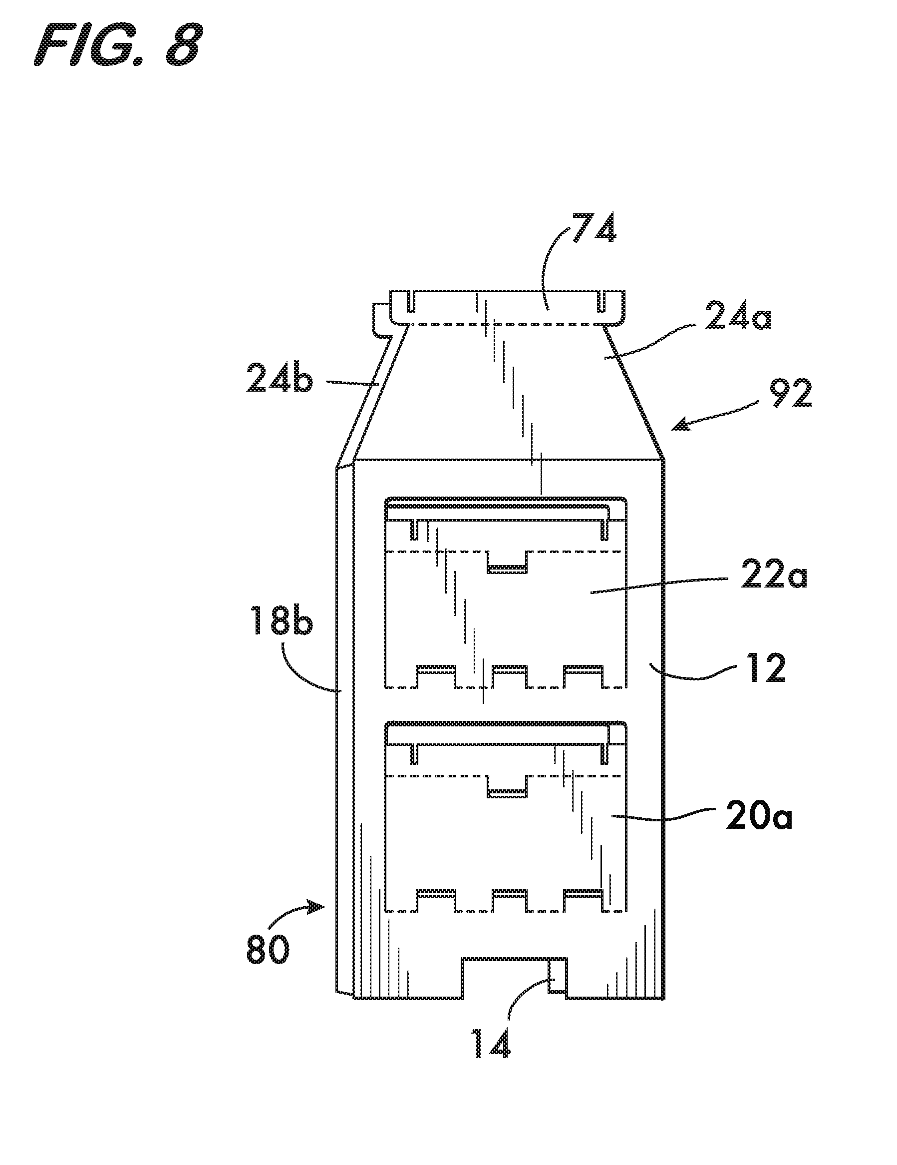
[0031] With further reference to FIGS. 6, 7, and 8, the KDF 80 can be configured into a bellows form 92 as seen in FIG. 8, which may be preferred for final assembly of the final merchandising display 10 at the retailer. As seen in FIGS. 6 and 7, the knockdown sections 90a, 90b are separated slightly from one another and the KDF corners 82, 86 are folded (angled) inward to form the bellows form 92 seen in FIG. 8 (in FIG. 7 the KDF corner 82 has been folded inward as indicated by arrow 94, while the KDF corner 86 has not yet been folded inward along arrow 94). As seen in FIGS. 7 and 8, similar to the knockdown form 80 of FIG. 5, the inner faces 52 of the front and back wall panels 12, 14 are in face-to-face relation as shown. Here, however, the front and back side wall sections 16a, 16b of the first side wall panel 16 are folded about corner 86 and the outer faces 54 thereof are in face to face relation, and the front and back side wall sections 18a, 18b of the second side wall panel 18 are folded about corner 82 and the outer faces 54 thereof are in face to face relation. Additionally, the inner face 52 of the front side wall section 16a a side portion of the inner face 52 of the front wall panel 12 are in face to face relation, the inner face 52 of the back side wall section 16b and a side portion of the inner face 52 of the back wall panel 14 are in face to face relation, the inner face 52 of the front side wall section 18a and the inner face 52 of the front wall panel 12 are in face to face relation, and the inner face 52 of the back side wall section 18b and a side portion of the inner face 52 of the back wall panel 14 are in face to face relation. In this form, the front and back side wall sections 16a, 16b of the first side wall panel 16 and the front and back side wall sections 18a, 18b of the second side wall panel 18 extend inwardly so as to be sandwiched between the front and back wall panels 12, 14 in the knockdown form as shown in FIG. 8. Thus, the bellows form 92 has a smaller width and the corners 82, 86 are now folded (angled) inwardly as will be in the final merchandising display 10 set up.
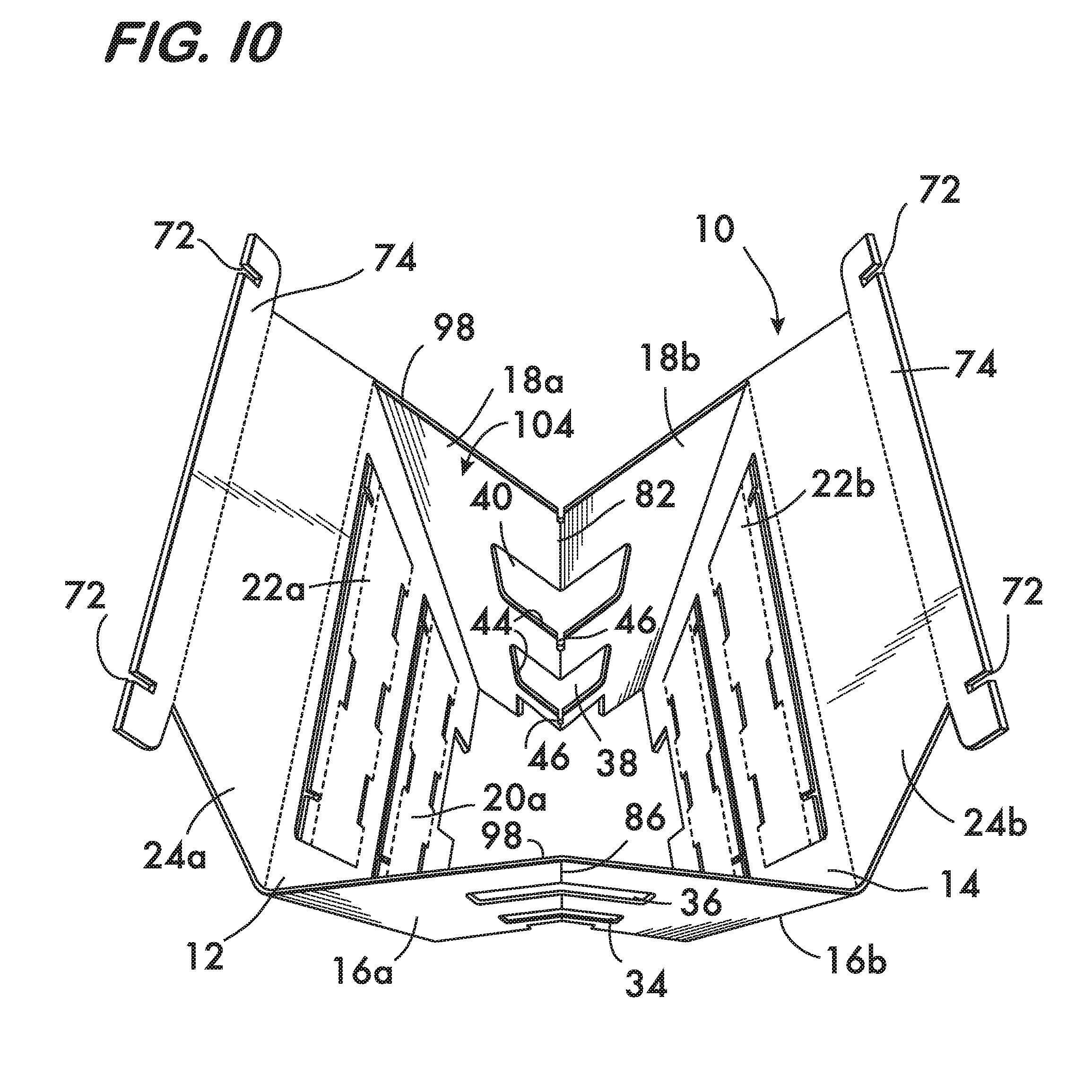
[0032] Assembly of the merchandising display 10 from the KDF forms 80, 92 is now described with further reference to FIGS. 9 through 19. If starting from the KDF form 80 as seen in FIG. 5, the first step is to separate the front and back wall panels 12, 14, moving the inner faces 52 of the side wall sections 16a, 16b, and 18a, 18b away from or out of their respective face to face relation, and fold the corners 82 and 86 inward as indicated by arrows 94 in FIG. 7 to arrive at the assembly as shown in FIGS. 9 and 10. The front and back wall panels 12, 14 need not be compressed to be close to one another as shown in FIG. 8, but is placed into the configuration shown in FIGS. 9 and 10 (FIG. 10 is a top view of the display 10 shown in FIG. 9). If starting from the KDF bellows form 92 of FIG. 8, the KDF 92 is opened by separating the front and back wall panels 12, 14 from each other in the configuration as shown in FIGS. 9 and 10, moving the outer faces 54 of the side wall sections 16a, 16b, and 18a, 18b away from or out of their respective face to face relation.
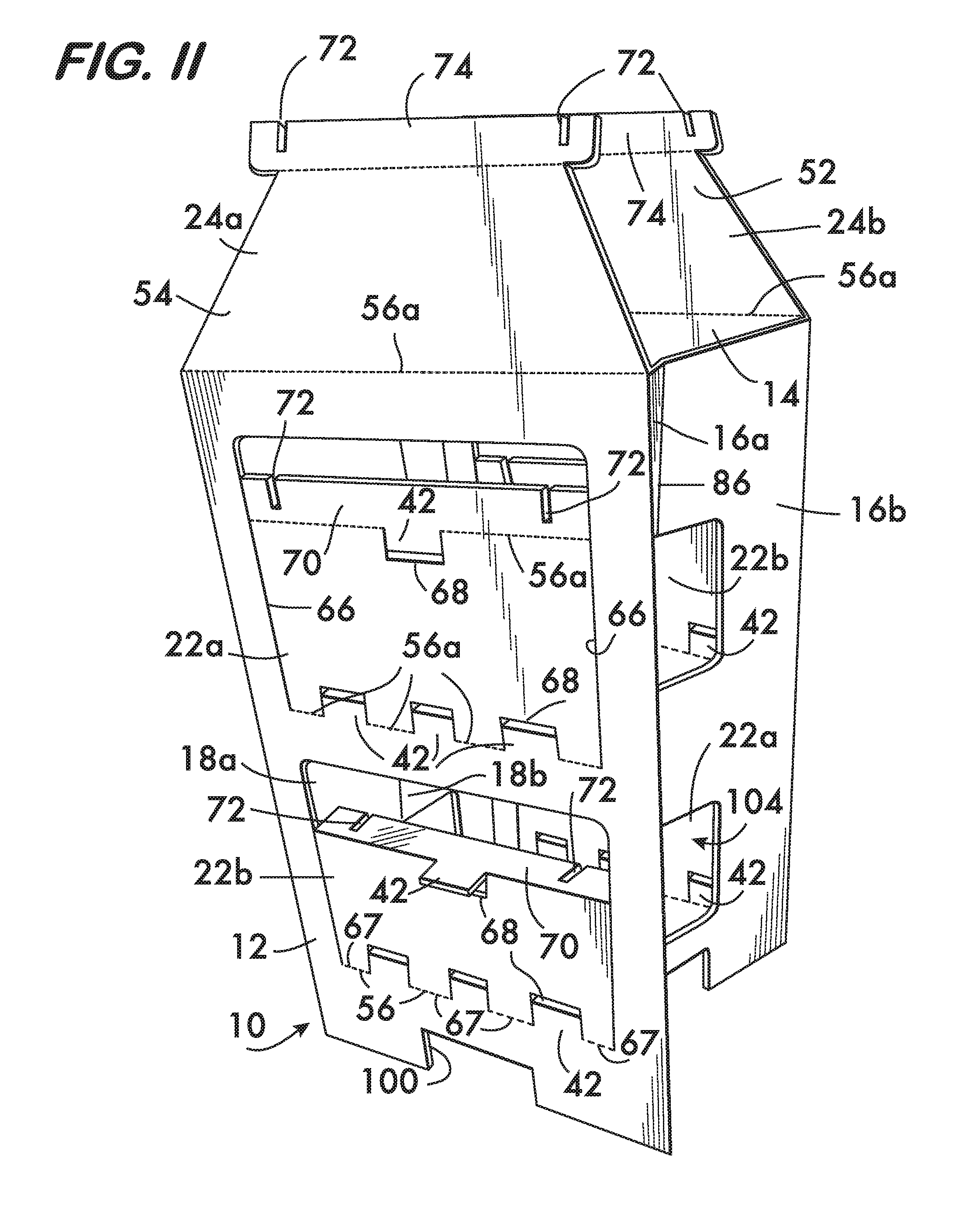
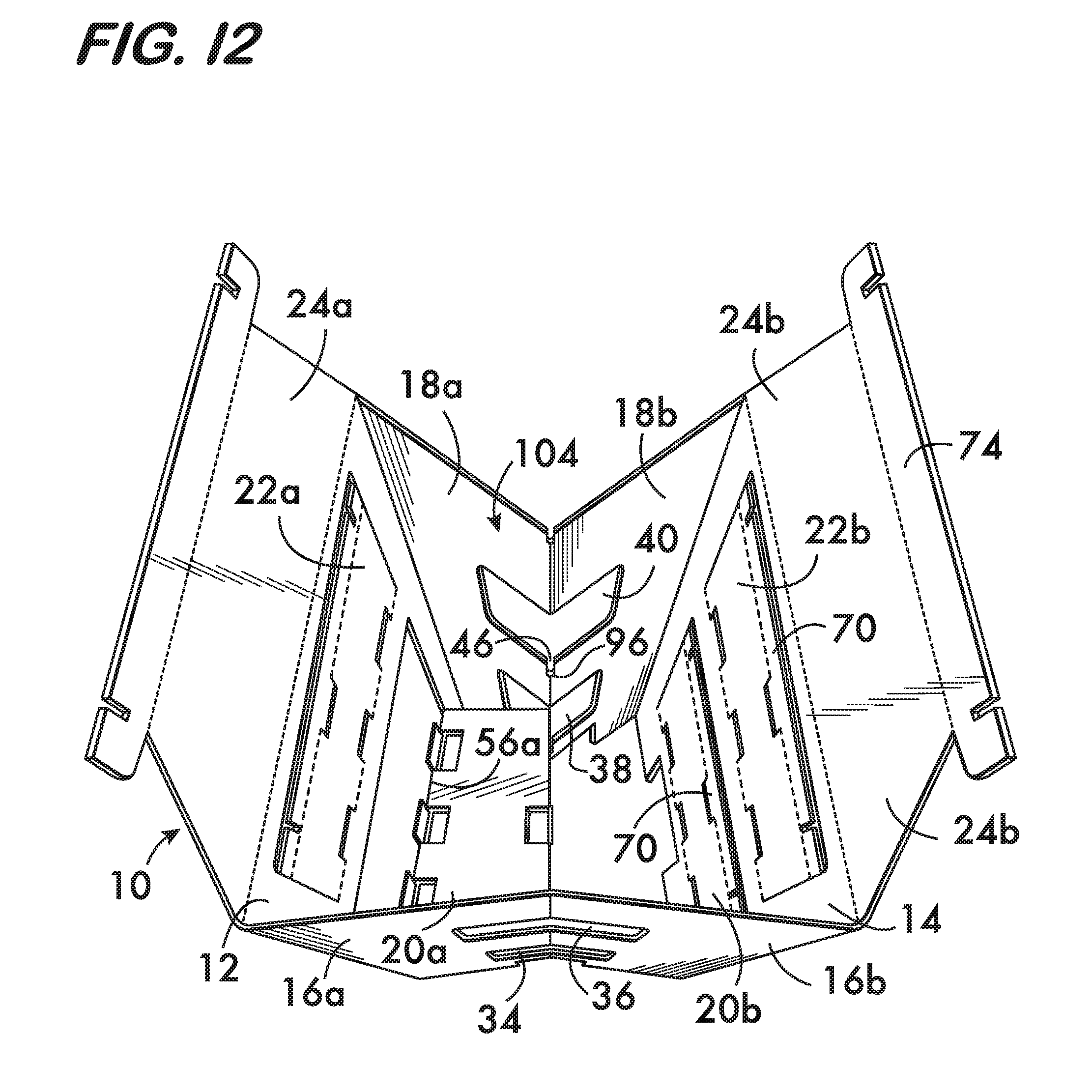
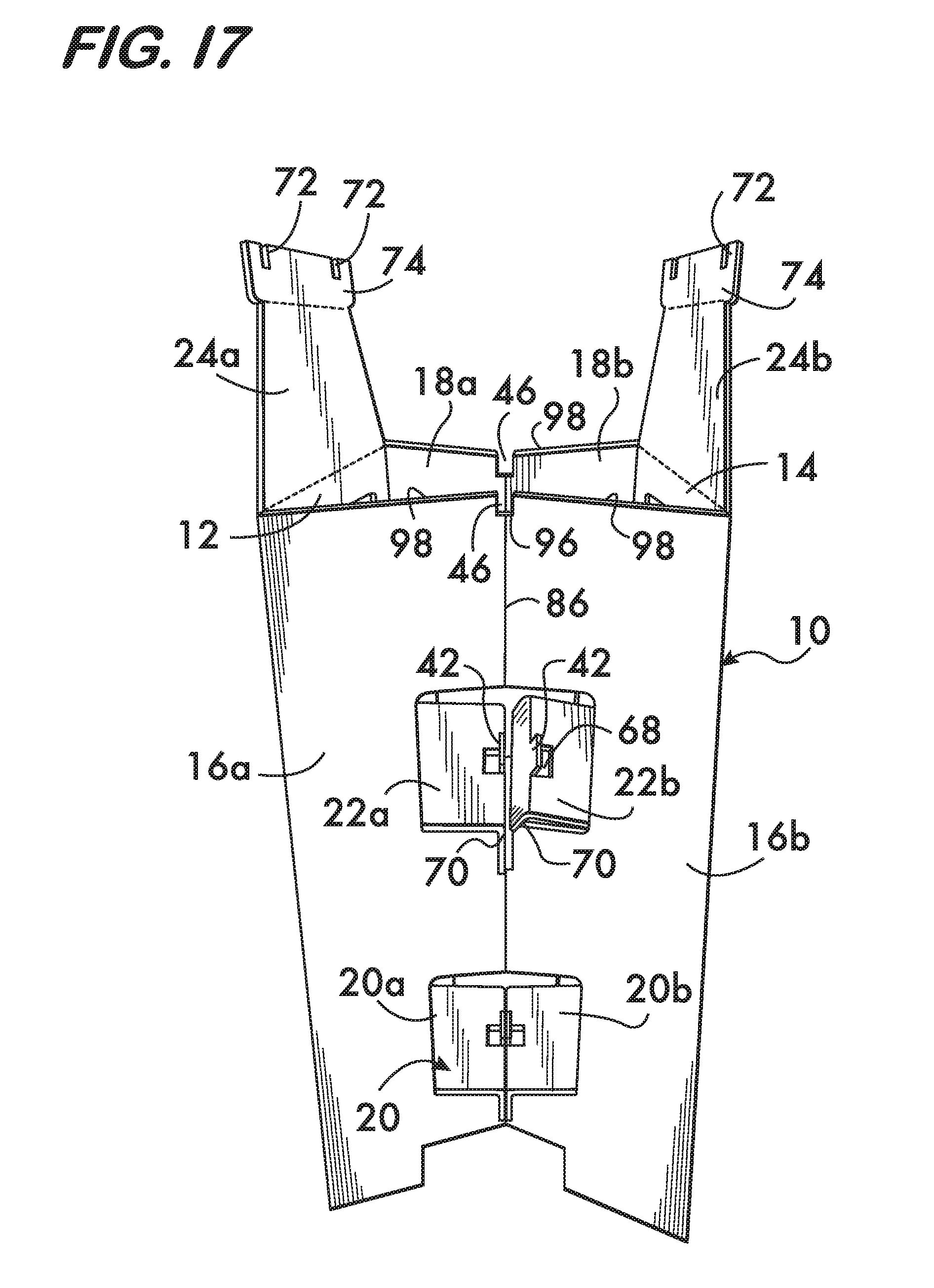
[0033] Next, with reference to FIGS. 11 through 18, the shelves 20, 22 are folded into place. With specific reference to FIGS. 11 and 12, shelf section 20a is folded inward (into the interior 104 of the display 10) about fold line 56a and its connection tab 70 is folded downward. The folding of the shelf section 20a continues until the slots 72 on the opposite ends of the connection tab 70 engage and receive therein complimentary slots 46 in the respective edges 44 of respective openings 34, 38 on opposing side walls 16, 18 as shown (see also FIG. 18). The two slots 46, 72 have ends 96 that may or may not come to abut one another. It is seen that the slots 46 and 72 each receive therein a cross sectional portion of the panel behind the slot end 96 in which the other slot is formed, thereby locking the two panels together. That is, slots 46 in the side walls 16 and 18 at the edges 44 receive therein respective cross sectional portions of the connection tab 70 while slots 72 of the connection tab 70 receive therein respective cross sectional portions of the side walls 16 and 18, thereby creating a friction like lock. Since the side walls 16, 18 are angled inwardly, a portion of the underside of the shelf section 20a is supported by the lower sections of the edges 44 of the openings 34 and 38 in the respective side walls 16 and 18 (see FIGS. 12, 1).
[0034] With further reference to FIG. 13, the second shelf section 20b is folded inward about fold line 56a and its connection tab 70 is folded downward such that the slots 72 on opposing sides of the connection tab 74 engage and receive therein complimentary slots 46 in the edges 44 of respective openings 34, 38 on opposing side walls 16, 18. A portion of the underside of the shelf section 20b is supported by the lower sections of the edges 44 of the openings 34 and 38 in respective side walls 16 and 18. The two shelf sections 20a, 20b, now substantially coplanar and adjacent one another, cooperate to form the complete shelf 20 to hold goods thereon, and can be accessed through the openings 26 and 30 created by the folding of the respective shelf sections 20a, 20b. It is seen that the folding of the shelf sections 20a, 20b and the connector tabs 70 form the tabs 42.
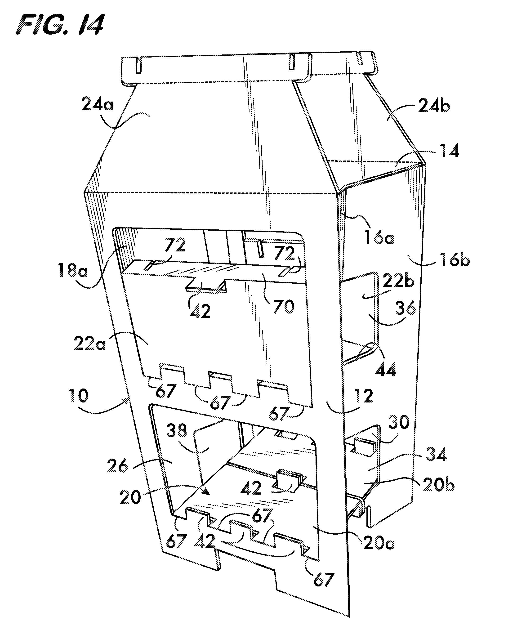
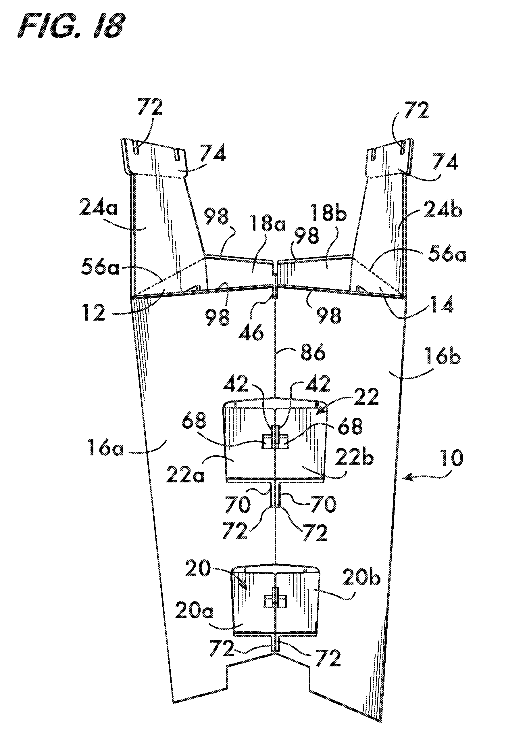
[0035] With reference to FIGS. 14 to 18, similar to shelf sections 20a, 20b, shelf sections 22a and 22b are likewise formed. The connection tabs 70 are folded downward such that the slots 72 on opposing sides of the connection tabs 70 engage complimentary slots 46 on the respective edges 44 of respective openings 36, 40 on opposing side walls 16 and 18. A portion of the underside of the shelf sections 22a and 22b are supported by the lower edges 44 of the openings 36 and 40 in respective side walls 16 and 18. This forms the upper shelf 22 as shown.
[0036] With reference to FIGS. 18, 19 and 1, similar to shelves 20a, 20b, and 22a, 22b, the top cover 24 is formed by folding top panel sections 24a and 24b. The top connector tabs 74 are folded downward such that the slots 72 on opposing sides of the connection tabs 74 engage and receive therein complimentary slots 46 on the top edges 98 of opposing side walls 16 and 18. The underside of the cover sections 24a and 24b is supported by the top edge 98 of the side walls 16 and 18 as shown. This completes the assembly forming the merchandising display 10 shown in FIG. 1. Once assembled, goods, such as bags of potato chips and pretzels are easily stacked on the shelves 20, 22, and held in place by the tabs 42.
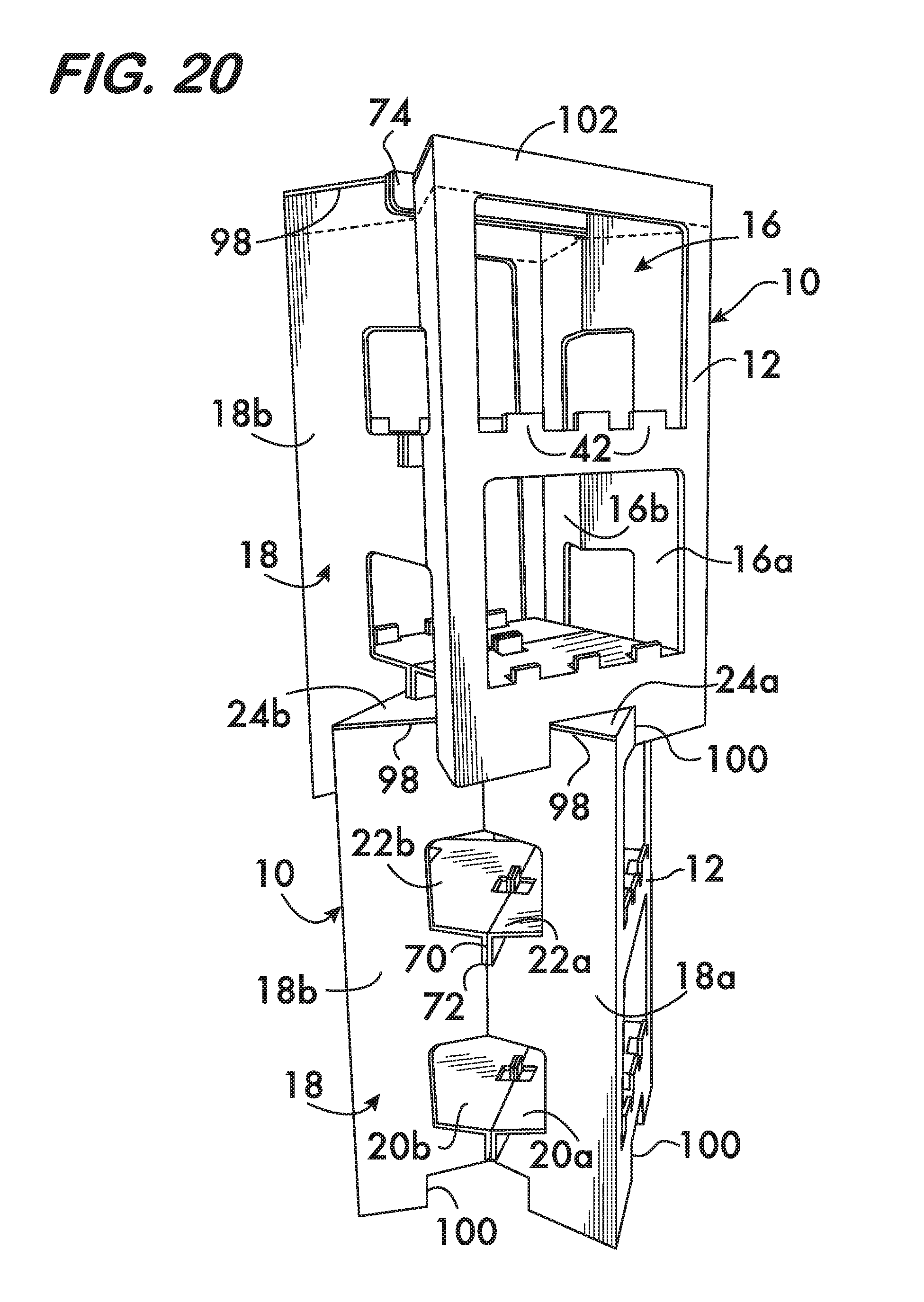
[0037] With further reference to FIG. 20, rectangular slots 100 on the bottom of the display 10 enable easy stacking of displays 10 one on top of another.
[0038] The invention as described above with reference to the illustrated example provides advantages such as quick set up time, easy set up, and minimal use of materials. It is appreciated that alternative features and embodiments of the present invention can be provided. For example, the merchandising display can have more or less then the two shelves 20, 22 as described above with reference to the illustrated embodiment. As another feature, a top 24 of a different shape can be provided, such as a rectangular top having rectangular top sections 24a, 24b, rather that the trapezoid shaped top sections 24a and 24b shown in the illustrated embodiment. Alternatively, a top 24 may not be provided, e.g., in FIG. 20, illustrated in the upper merchandising display 10, a merchandising display can be provided without an upper section 102 defined by broken line, leaving just the upper sections of the front 12, back 14 and sidewalls 16, 18.
[0039] While particular embodiments of the invention are described herein, it is not intended to limit the invention to such disclosure. Changes and modifications may be incorporated and embodied within the scope of the appended claims.
* * * * *
D00000
D00001
D00002
D00003
D00004
D00005
D00006
D00007
D00008
D00009
D00010
D00011
D00012
D00013

D00014
D00015

D00016

D00017
D00018
D00019

D00020
XML
uspto.report is an independent third-party trademark research tool that is not affiliated, endorsed, or sponsored by the United States Patent and Trademark Office (USPTO) or any other governmental organization. The information provided by uspto.report is based on publicly available data at the time of writing and is intended for informational purposes only.
While we strive to provide accurate and up-to-date information, we do not guarantee the accuracy, completeness, reliability, or suitability of the information displayed on this site. The use of this site is at your own risk. Any reliance you place on such information is therefore strictly at your own risk.
All official trademark data, including owner information, should be verified by visiting the official USPTO website at www.uspto.gov. This site is not intended to replace professional legal advice and should not be used as a substitute for consulting with a legal professional who is knowledgeable about trademark law.