Foldable Ring
YEP; Mau Koung
U.S. patent application number 15/652121 was filed with the patent office on 2019-01-17 for foldable ring. This patent application is currently assigned to New Atlantic Assets Limited. The applicant listed for this patent is New Atlantic Assets Limited. Invention is credited to Mau Koung YEP.
| Application Number | 20190014869 15/652121 |
| Document ID | / |
| Family ID | 64999943 |
| Filed Date | 2019-01-17 |
View All Diagrams
| United States Patent Application | 20190014869 |
| Kind Code | A1 |
| YEP; Mau Koung | January 17, 2019 |
Foldable Ring
Abstract
A foldable ring includes a main ring and a flipper. The main ring has a first inner peripheral surface, a first outer peripheral surface, a first front surface, a first rear surface, and a first through cavity formed as a space surrounded by the first inner peripheral surface. The flipper has a second inner peripheral surface, a second outer peripheral surface, a second front surface, a second rear surface, and a second through cavity formed as a space surrounded by the second inner peripheral surface. The flipper is pivotally attached on the first front surface to move between a first and second position. In either the first or second position, the flipper is arranged to overlap on the first front surface and that the first through cavity is arranged to align with the second through cavity to allow a user's finger to pass through both main ring and flipper.
| Inventors: | YEP; Mau Koung; (Hong Kong, HK) | ||||||||||
| Applicant: |
|
||||||||||
|---|---|---|---|---|---|---|---|---|---|---|---|
| Assignee: | New Atlantic Assets Limited |
||||||||||
| Family ID: | 64999943 | ||||||||||
| Appl. No.: | 15/652121 | ||||||||||
| Filed: | July 17, 2017 |
| Current U.S. Class: | 1/1 |
| Current CPC Class: | A44C 9/00 20130101; A44C 9/0084 20130101; A44C 17/02 20130101; A44C 17/00 20130101; A44C 9/0015 20130101; A44C 9/0053 20130101 |
| International Class: | A44C 9/00 20060101 A44C009/00; A44C 17/02 20060101 A44C017/02 |
Claims
1. A foldable ring, comprising: a main ring having a first inner peripheral surface, a first outer peripheral surface, a first front surface, a first rear surface, and a first through cavity formed as a space surrounded by said first inner peripheral surface; and a flipper having a second inner peripheral surface, a second outer peripheral surface, a second front surface, a second rear surface, and a second through cavity formed as a space surrounded by said second inner peripheral surface, said flipper being pivotally attached on said first front surface to move between a first position and a second position, wherein in either said first position or said second position, said flipper is arranged to pivotally move to overlap on said first front surface of said main ring and that said first through cavity is arranged to align with said second through cavity so as to allow a user's finger to pass through both said main ring and said flipper.
2. The foldable ring, as recited in claim 1, wherein a cross sectional shape of said flipper is substantially the same as that of an overlapping portion of said main ring.
3. The foldable ring, as recited in claim 2, further comprising a hinge mechanism provided on said main ring for connecting with said flipper for moving said flipper between said first position and said second position.
4. The foldable ring, as recited in claim 3, wherein said hinge mechanism is provided along an axis of symmetry of said main ring.
5. The foldable ring, as recited in claim 3, wherein said hinge mechanism comprises a connector provided on said main ring, and a bolt inserted into a hole on said connector for connecting said main ring to said flipper.
6. The foldable ring, as recited in claim 1, further comprising a stone setting as a part connecting said main ring for receiving and setting a main ornament stone.
7. The foldable ring, as recited in claim 1, further comprising at least an ornament article provided on at least said first inner peripheral surface, said first outer peripheral surface, said first front surface, said first rear surface, said second inner peripheral surface, said second outer peripheral surface, said second front surface, and said second rear surface.
8. The foldable ring, as recited in claim 7, wherein said ornament article comprises at least one of an engraved slot and a secondary ornamental stone.
9. The foldable ring, as recited in claim 1, wherein said main ring has at least one of a substantially circular cross sectional shape, a substantially quadrilateral cross sectional shape, and a substantially elliptical cross sectional shape.
10. A foldable ring, comprising: a main ring having a first inner peripheral surface, a first outer peripheral surface, a first front surface, a first rear surface, and a first through cavity formed as a space surrounded by said first inner peripheral surface; and a flipper having a second inner peripheral surface, a second outer peripheral surface, a second front surface, a second rear surface, and a second through cavity formed as a space surrounded by said second inner peripheral surface, said flipper being pivotally attached on said first front surface to move between a first position and a second position; and an auxiliary flipper having a third inner peripheral surface, a third outer peripheral surface, a third front surface, a third rear surface, and a third through cavity formed as a space surrounded by said third inner peripheral surface, said auxiliary flipper being pivotally attached on said first rear surface to move between a first position and a second position; wherein in either said first position or said second position, said flipper and said auxiliary flipper are arranged to pivotally move to overlap on said first front surface and said first rear surface of said main ring respectively and that said first through cavity is arranged to align with said second through cavity and said third through cavity so as to allow a user's finger to pass through said main ring, said flipper and said auxiliary flipper.
11. The foldable ring, as recited in claim 10, wherein a cross sectional shape of said flipper and said auxiliary flipper is substantially the same as that of an overlapping portion of said main ring.
12. The foldable ring, as recited in claim 11, further comprising a hinge mechanism provided on said main ring for connecting with said flipper and said auxiliary flipper for moving said flipper and said auxiliary flipper between said first position and said second position.
13. The foldable ring, as recited in claim 12, wherein said hinge mechanism is provided along an axis of symmetry of said main ring.
14. The foldable ring, as recited in claim 12, wherein said hinge mechanism comprises a connector provided on said main ring, and a bolt inserted into a hole on said connector for connecting said main ring to said corresponding flipper and said auxiliary flipper.
15. The foldable ring, as recited in claim 10, further comprising a stone setting as a part connecting said main ring for receiving and setting a main ornament stone.
16. The foldable ring, as recited in claim 10, further comprising at least an ornament article provided on at least said first inner peripheral surface, said first outer peripheral surface, said first front surface, said first rear surface, said second inner peripheral surface, said second outer peripheral surface, said second front surface, said second rear surface, said third inner peripheral surface, said third outer peripheral surface, said third front surface, and said third rear surface.
17. The foldable ring, as recited in claim 16, wherein said ornament article comprises at least one of an engraved slot and a secondary ornamental stone.
18. The foldable ring, as recited in claim 10, wherein said main ring has at least one of a substantially circular cross sectional shape, a substantially quadrilateral cross sectional shape, and a substantially elliptical cross sectional shape.
Description
BACKGROUND OF THE PRESENT INVENTION
Field of Invention
[0001] The present invention relates to a ring, and more particularly to a jewel ring with a foldable feature such then a user may selectively fold the ring in a predetermined combination as a personal customized luxury item.
Description of Related Arts
[0002] There are many convention jewel ring designs. The most common ring is just a simple circular ring forming a through cavity in which a user may insert his/her finger through it. Since this design could only be worn in a single way, the display effect is extremely limited. If the user gets bored with wearing the same jewel ring with the same display every day, it is necessary for the user to switch to another jewel ring.
[0003] Some of the jewel rings are customized by mounting different gems or diamonds, or by having different cross-sectional shapes. Mounting different gems or diamonds is usually the most effective way to customize a jewel ring as the gems or diamonds are usually extremely eye-catching. Thus, different gems or diamonds can significantly enhance the display effect of the ring. A major disadvantage is that these gems and diamonds are very expensive as they are considered rare. These kinds of jewel rings are usually very costly. Designs of different cross-sectional shapes of the rings are often bound to the physical limitation of a human finger. The size of the ring is also limited since it is designed to be worn by human.
[0004] As one may see from the above, there are problems with these conventional design jewel rings. Thus, there is a need to invent a single jewel ring which provides more customizations in which the user may enjoy wearing it on a daily basis without switching to another jewel ring.
SUMMARY OF THE PRESENT INVENTION
[0005] The present invention provides a foldable jewel ring which a user may selectively fold the ring for customization to wear it.
[0006] In one aspect of the present invention, it provides a foldable ring, comprising:
[0007] a main ring having a first inner peripheral surface, a first outer peripheral surface, a first front surface, a first rear surface, and a first through cavity formed as a space surrounded by said first inner peripheral surface; and
[0008] a flipper having a second inner peripheral surface, a second outer peripheral surface, a second front surface, a second rear surface, and a second through cavity formed as a space surrounded by the second inner peripheral surface, the flipper being pivotally attached on the first front surface to move between a first position and a second position, wherein in either the first position or the second position, the flipper is arranged to pivotally move to overlap on the first front surface of the main ring and that the first through cavity is arranged to align with the second through cavity so as to allow a user's finger to pass through both the main ring and the flipper.
[0009] In another aspect of the present invention, it provides a foldable ring, comprising:
[0010] a main ring having a first inner peripheral surface, a first outer peripheral surface, a first front surface, a first rear surface, and a first through cavity formed as a space surrounded by the first inner peripheral surface; and
[0011] a flipper having a second inner peripheral surface, a second outer peripheral surface, a second front surface, a second rear surface, and a second through cavity formed as a space surrounded by the second inner peripheral surface, the flipper being pivotally attached on the first front surface to move between a first position and a second position; and
[0012] an auxiliary flipper having a third inner peripheral surface, a third outer peripheral surface, a third front surface, a third rear surface, and a third through cavity formed as a space surrounded by the third inner peripheral surface, the auxiliary flipper being pivotally attached on the first rear surface to move between a first position and a second position;
[0013] wherein in either the first position or the second position, the flipper and the auxiliary flipper are arranged to pivotally move to overlap on the first front surface and the first rear surface of the main ring respectively and that the first through cavity is arranged to align with the second through cavity and the third through cavity so as to allow a user's finger to pass through the main ring, the flipper and the auxiliary flipper.
[0014] This summary presented above is provided merely to introduce certain concepts and not to identify any key or essential features of the claimed subject matter.
BRIEF DESCRIPTION OF THE DRAWINGS
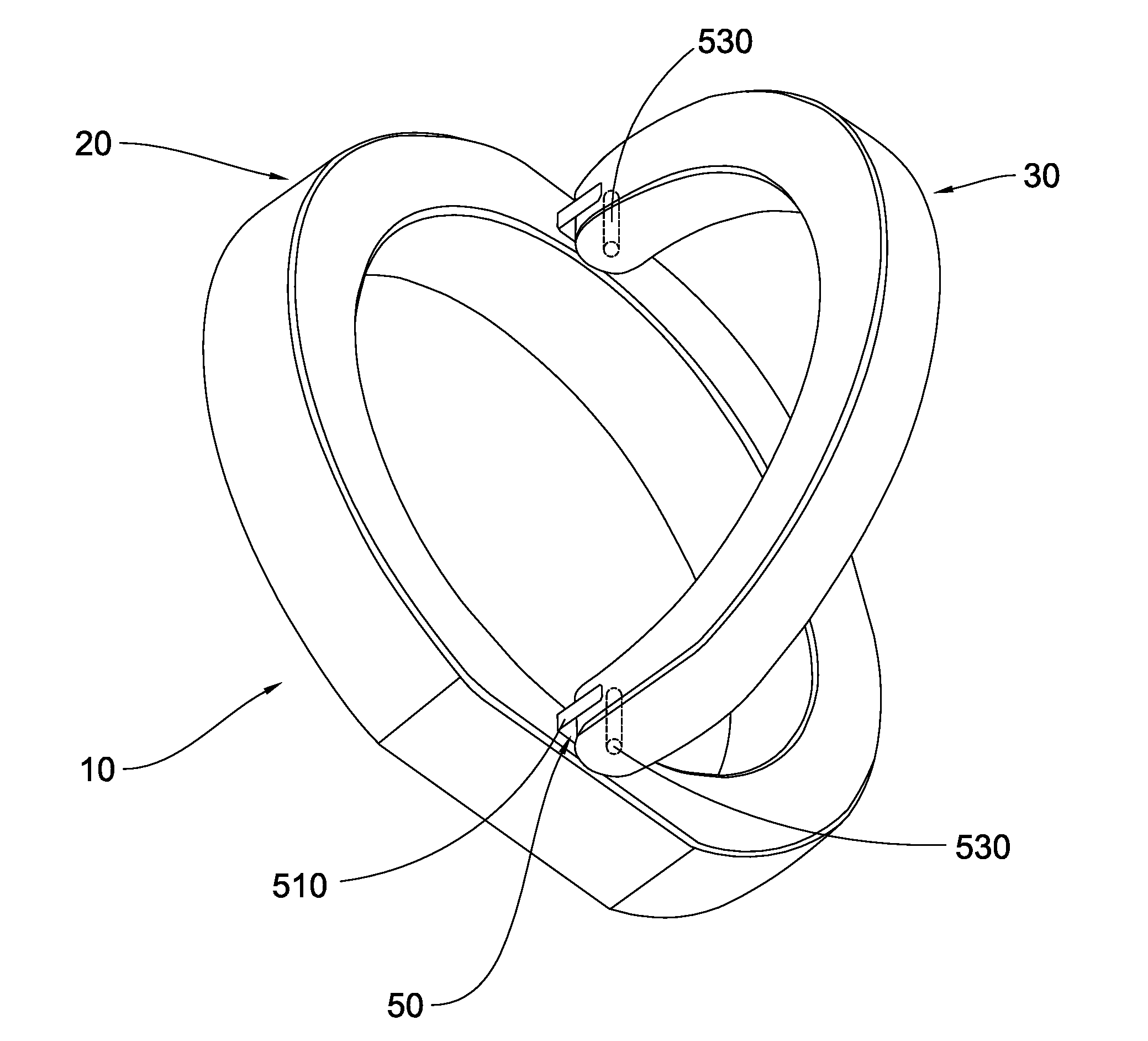
[0015] FIG. 1 is a perspective view of a foldable ring according to a first preferred embodiment of the present invention, illustrating that a flipper is attached on a main ring of the foldable ring.
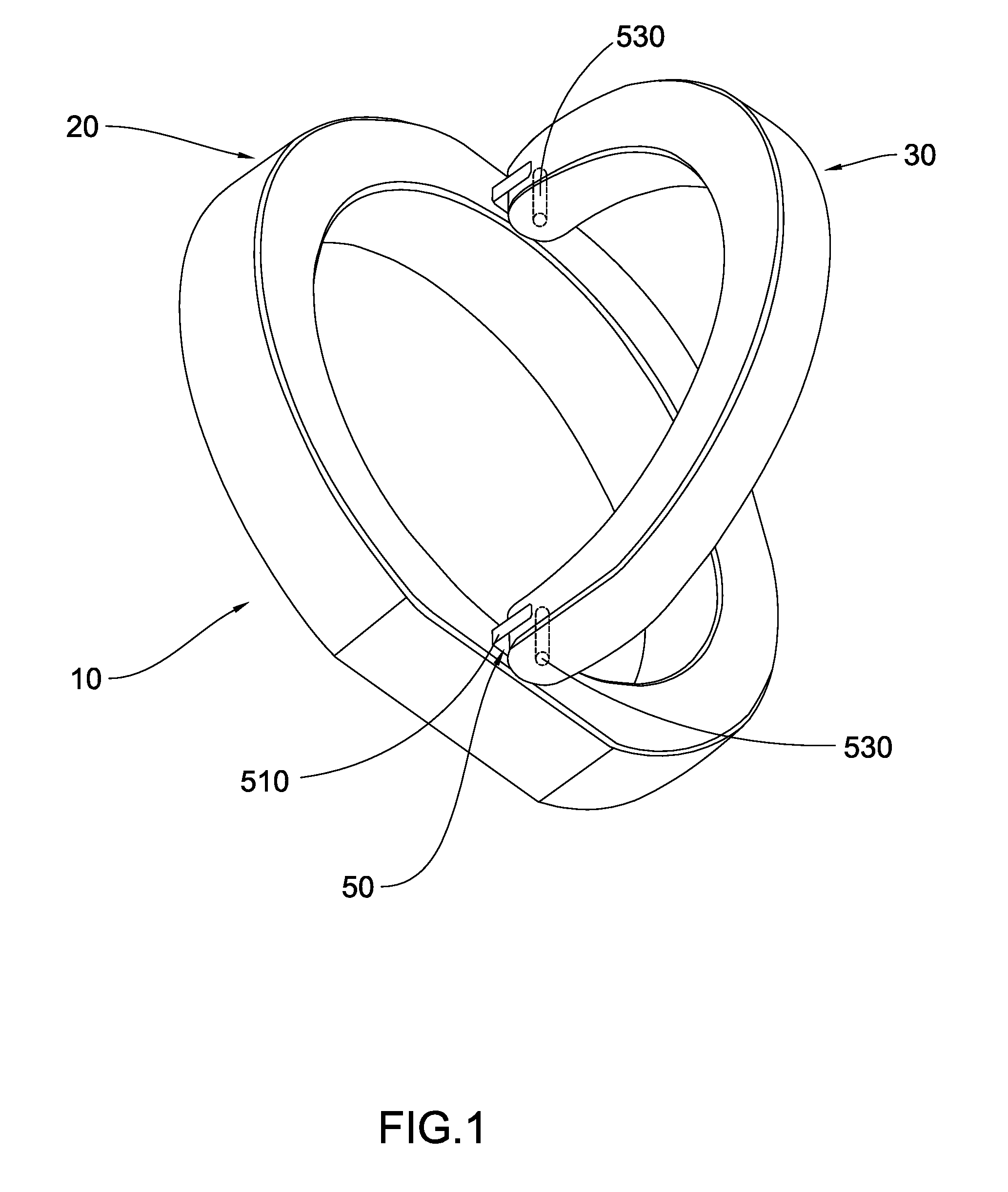
[0016] FIG. 2 is a first perspective view of the main ring according to the first preferred embodiment of the present invention, illustrating the different surfaces of the main ring.
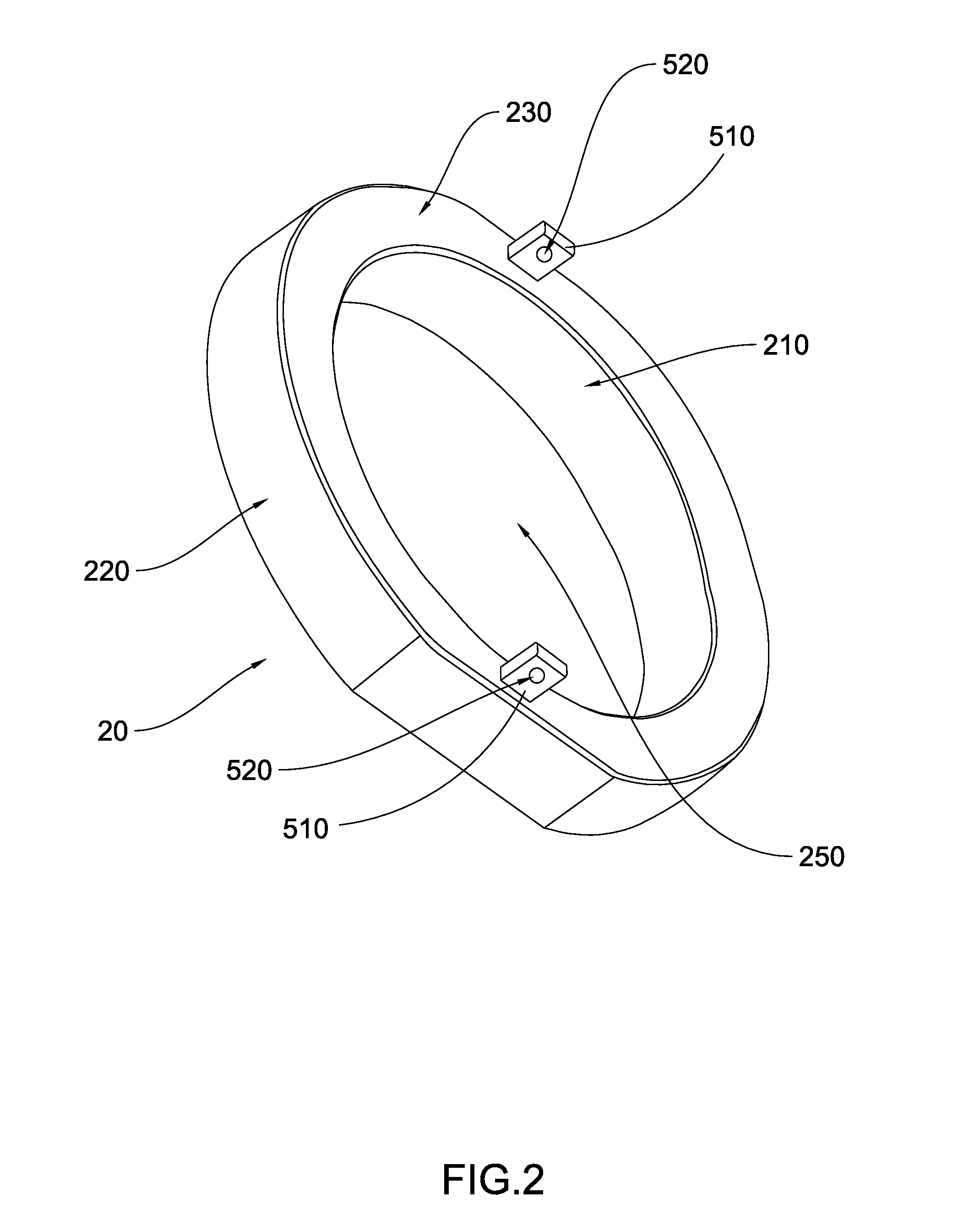
[0017] FIG. 3 is a second perspective view of the main ring according to the first preferred embodiment of the present invention, illustrating the different surfaces of the main ring.
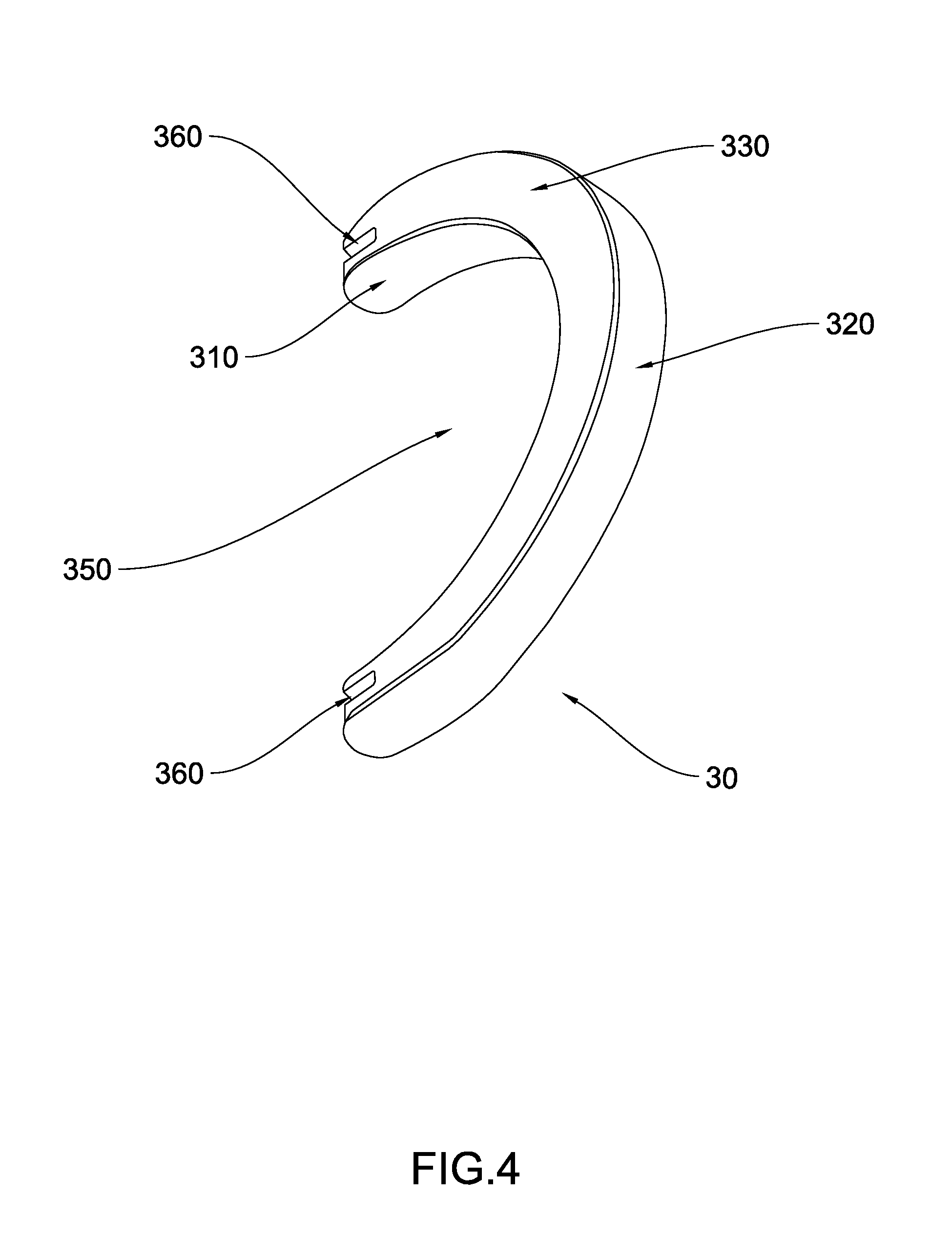
[0018] FIG. 4 is a first perspective view of the flipper according to the first preferred embodiment of the present invention, illustrating the different surfaces of the flipper.
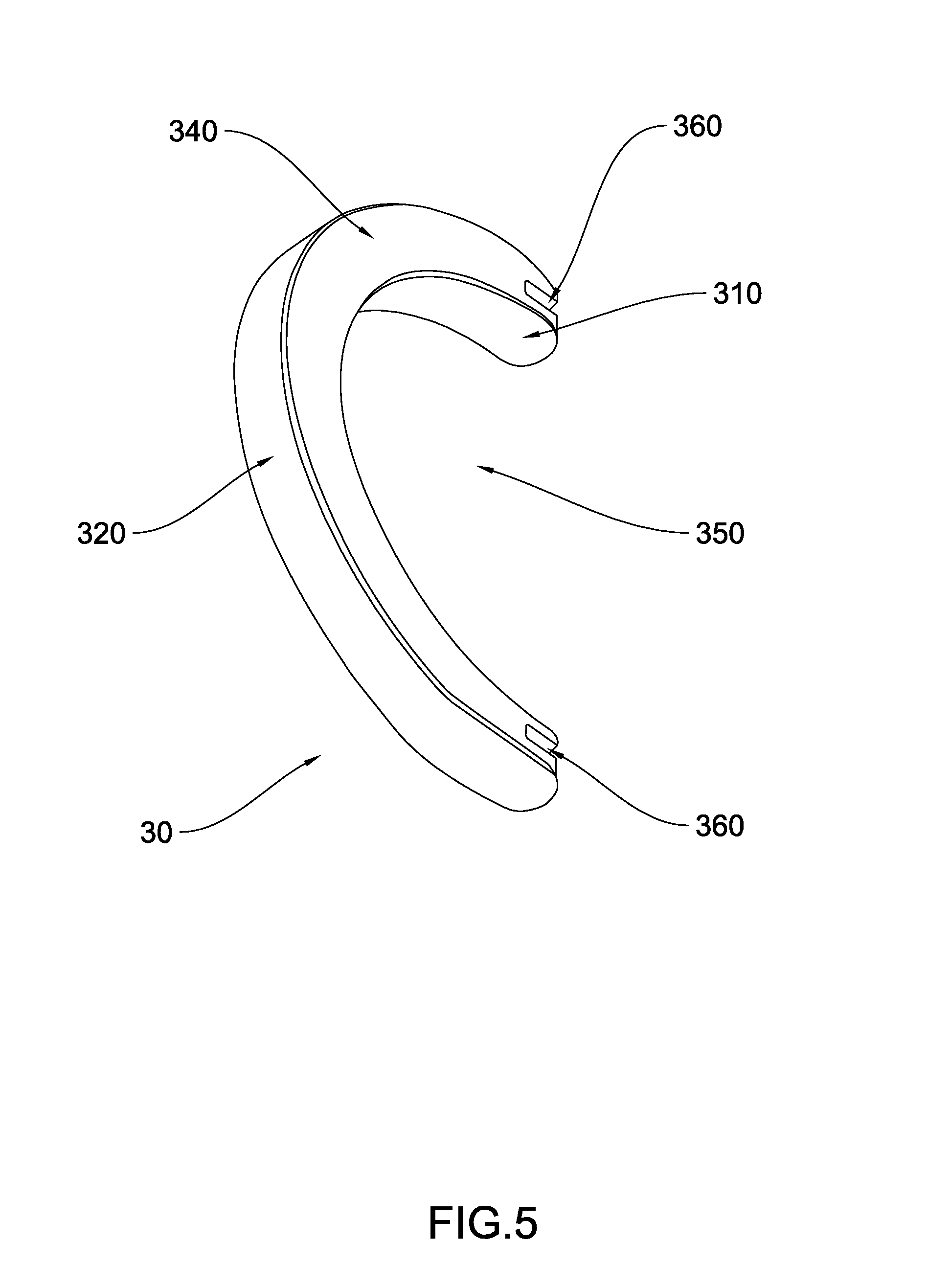
[0019] FIG. 5 is a second perspective view of the flipper according to the first preferred embodiment of the present invention, illustrating the different surfaces of the flipper.
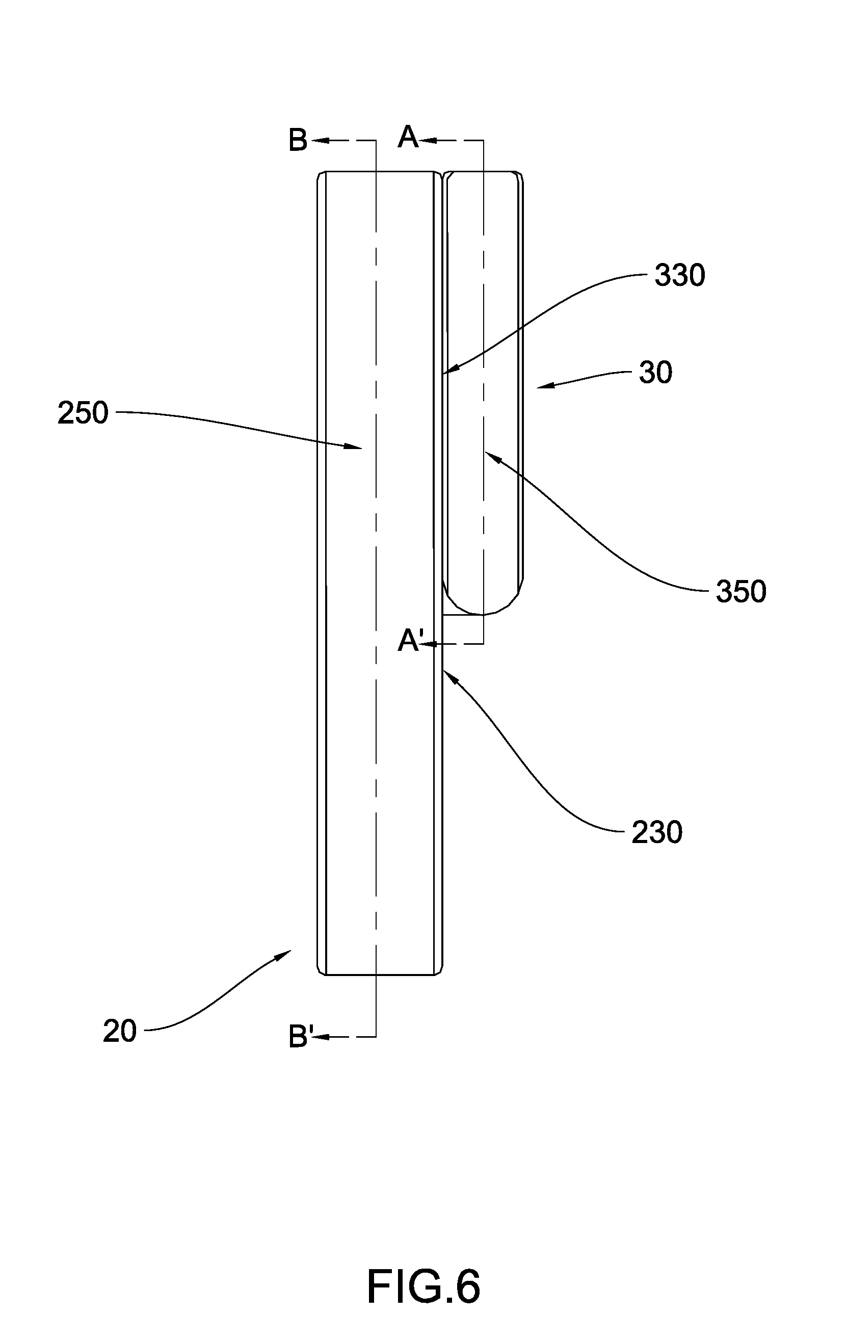
[0020] FIG. 6 is a side view of the foldable ring illustrating the flipper in the first position according to the first preferred embodiment of the present invention.
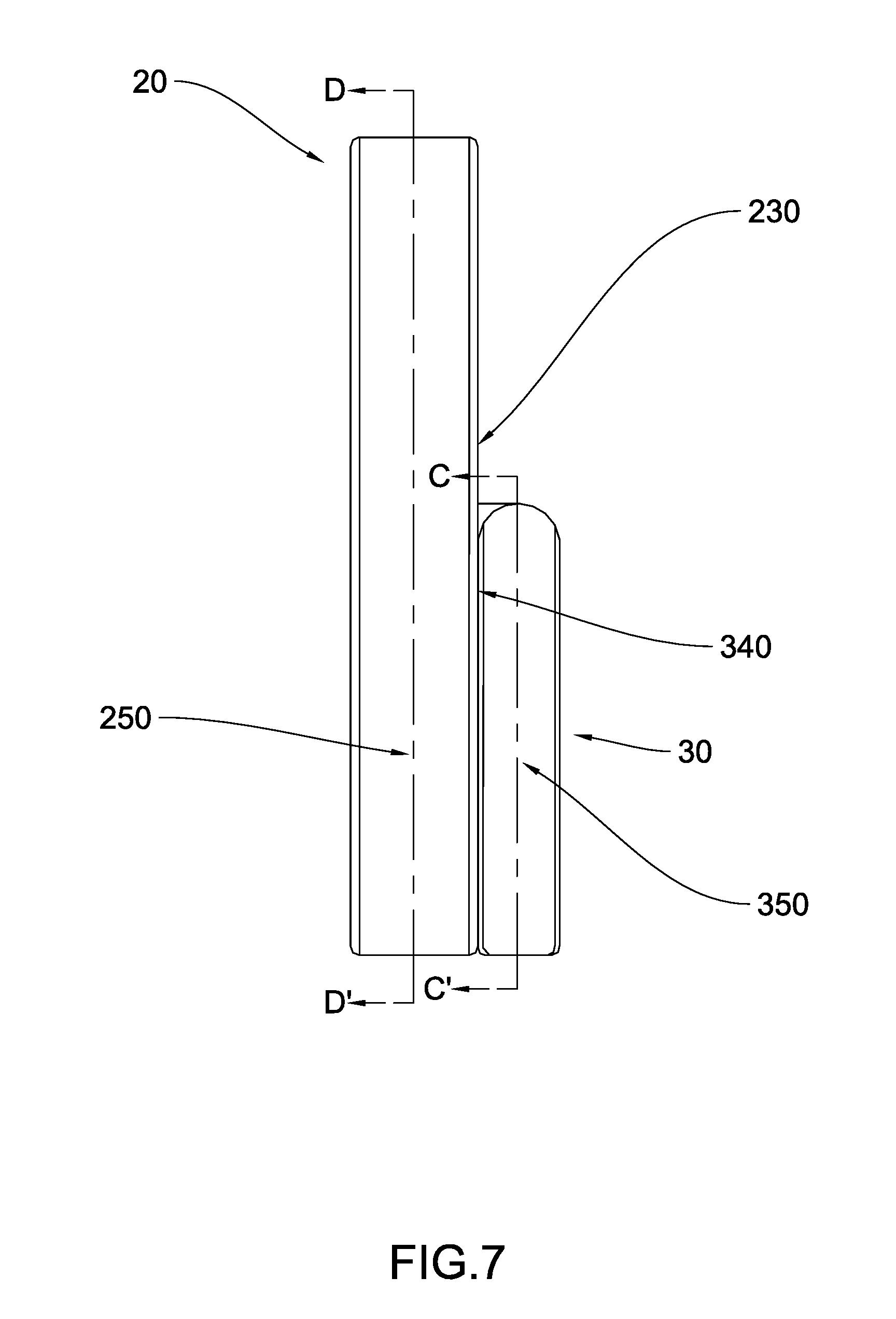
[0021] FIG. 7 is a side view of the foldable ring illustrating the flipper in the second position according to the first preferred embodiment of the present invention.
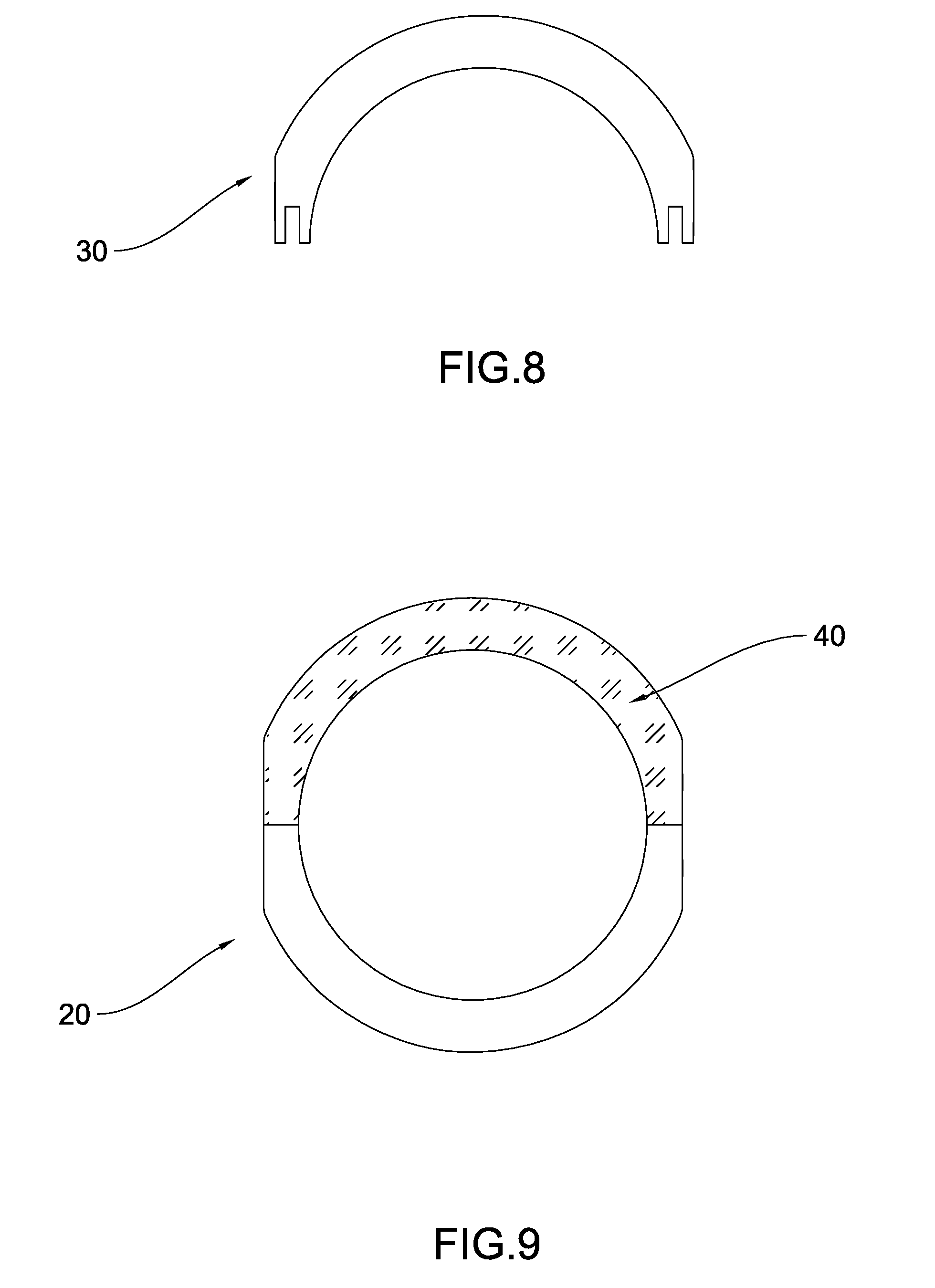
[0022] FIG. 8 is a cross sectional view of section A-A' according to the first preferred embodiment of the present invention illustrating the cross sectional shape of the flipper in the first position.
[0023] FIG. 9 is a cross sectional view of section B-B' according to the first preferred embodiment of the present invention illustrating the overlapping portion of the main ring when the flipper is in the first position.
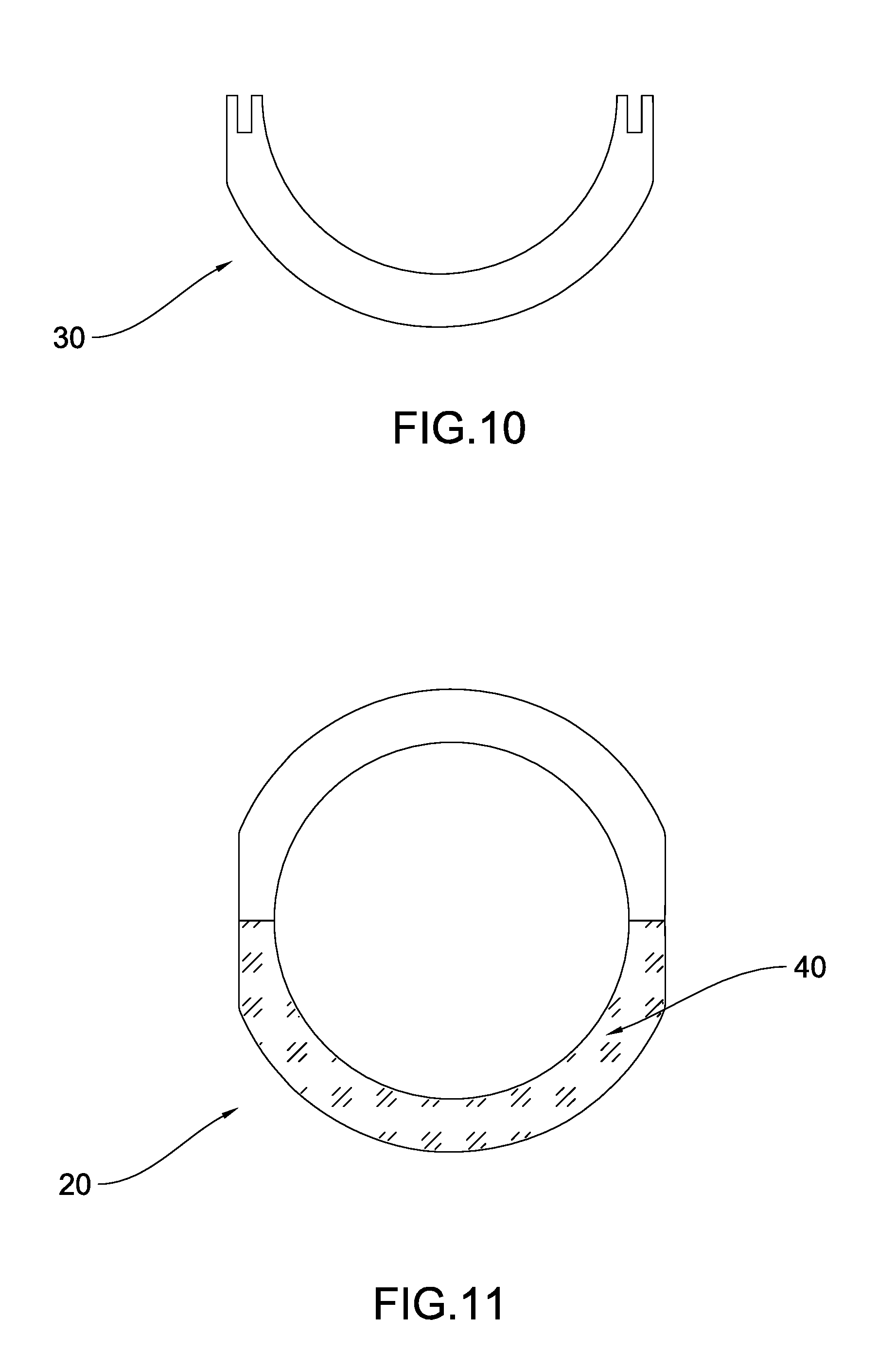
[0024] FIG. 10 is a cross sectional view of section C-C' according to the first preferred embodiment of the present invention illustrating the cross sectional shape of the flipper in the second position.
[0025] FIG. 11 is a cross sectional view of section D-D' according to the first preferred embodiment of the present invention illustrating the overlapping portion of the main ring when the flipper is in the second position.
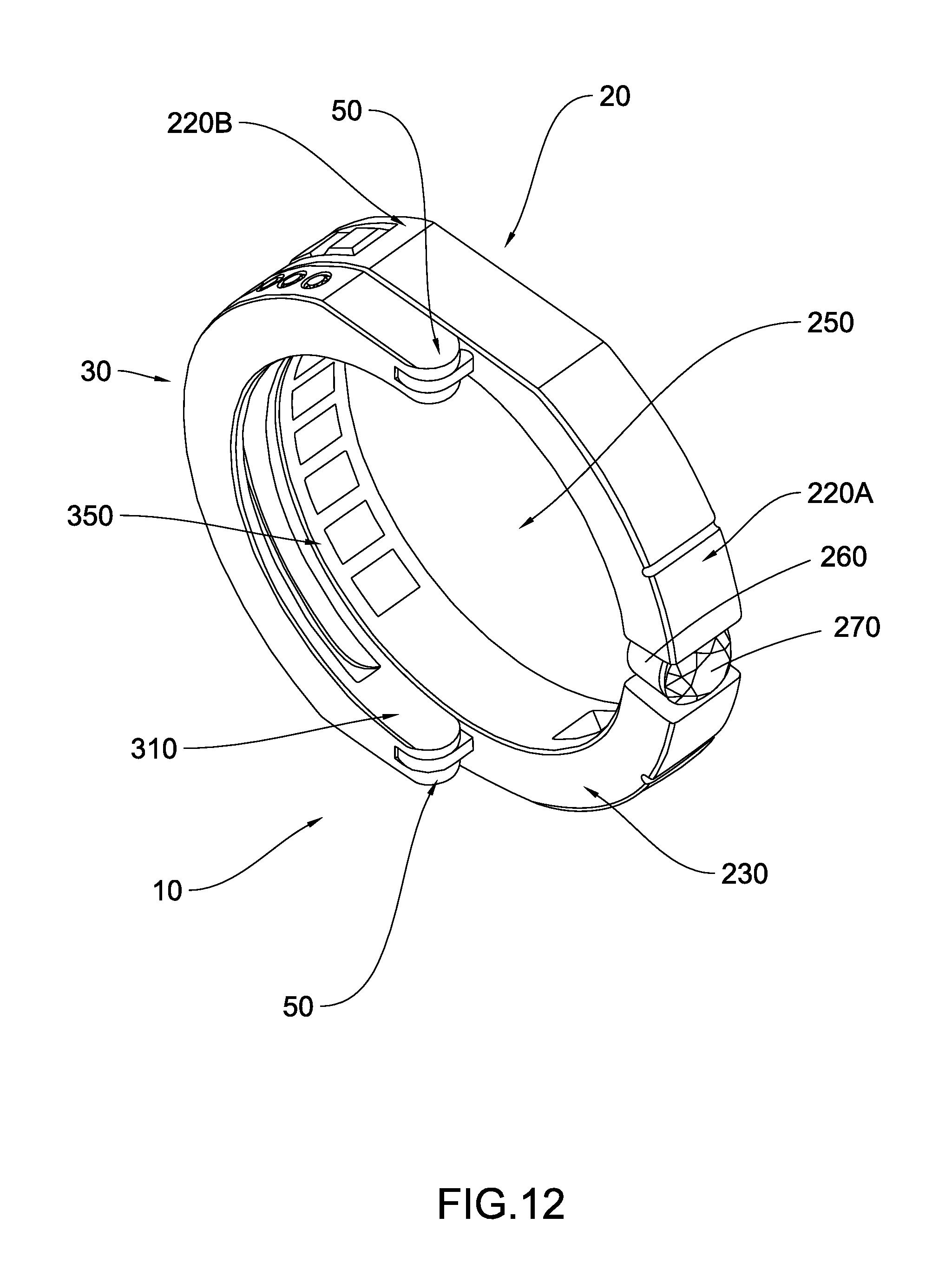
[0026] FIG. 12 is a perspective view of the foldable ring according to the first preferred embodiment of the present invention, illustrating the flipper in the first position.
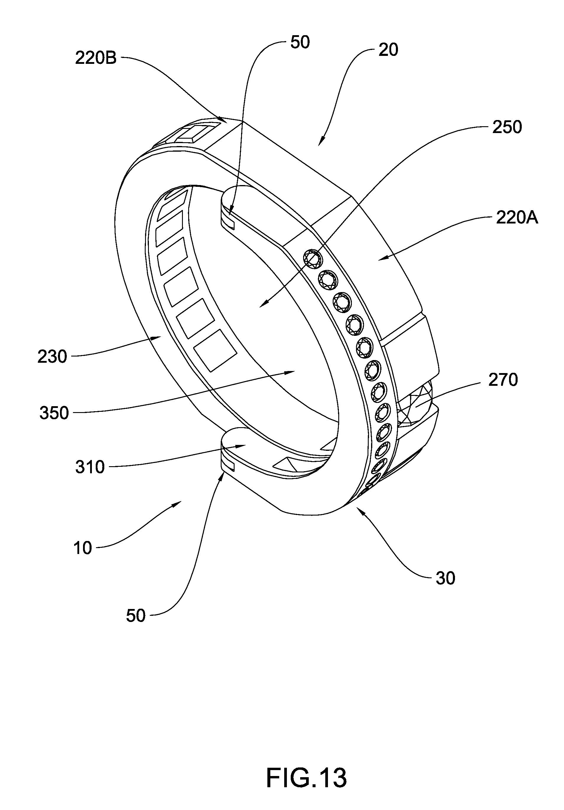
[0027] FIG. 13 is a perspective view of the foldable ring according to the first preferred embodiment of the present invention, illustrating the flipper in the second position.
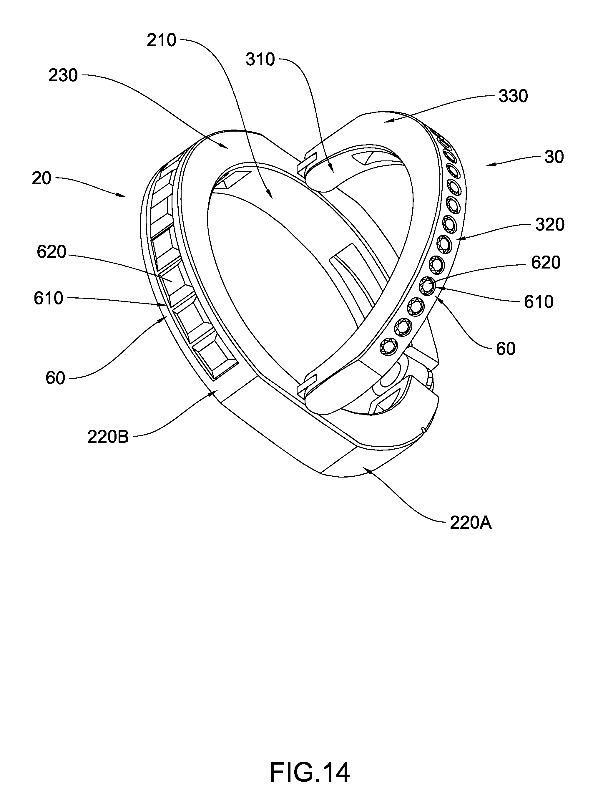
[0028] FIG. 14 is a perspective view of the foldable ring according to the first preferred embodiment of the present invention, illustrating different ornaments being provided on the foldable ring.
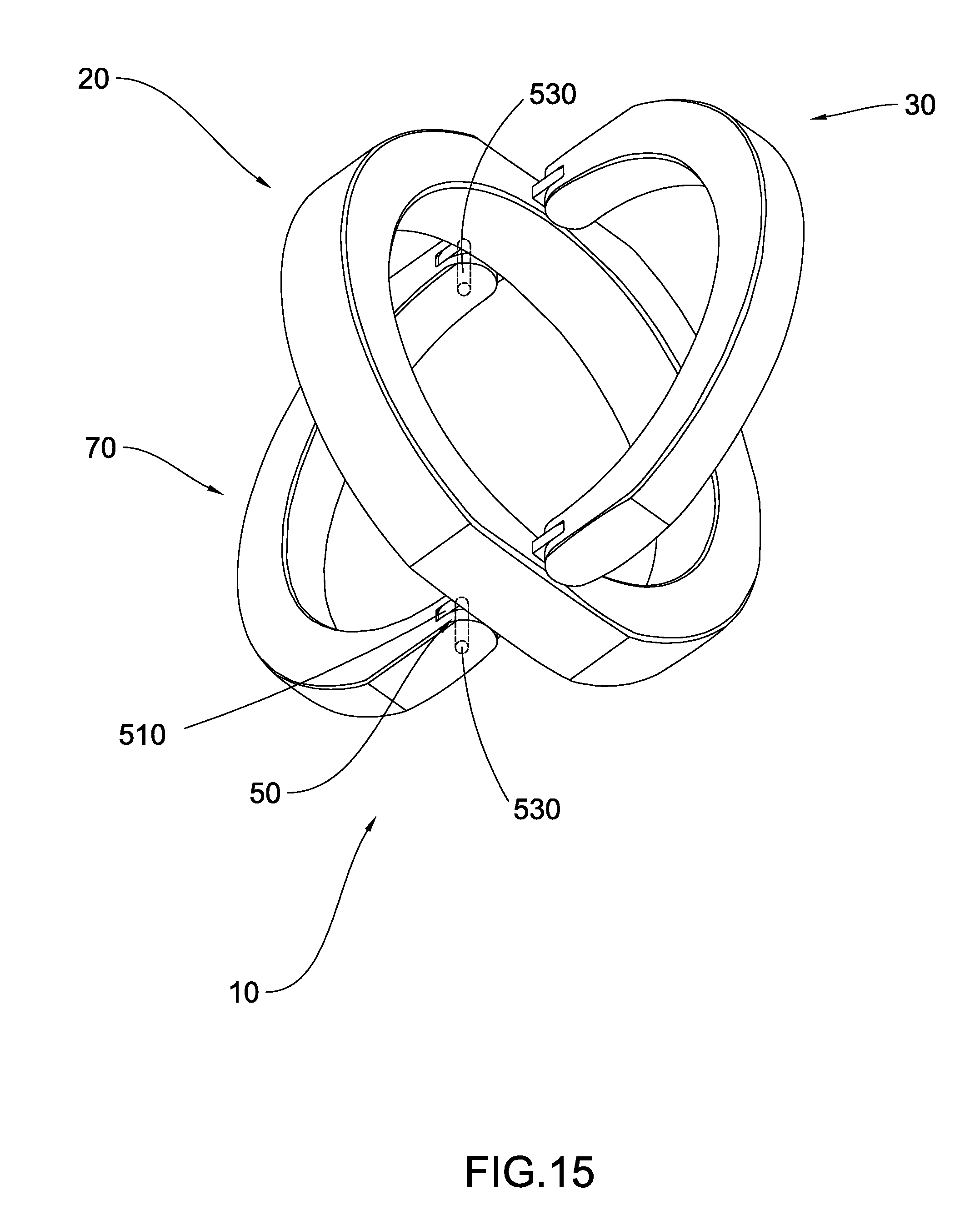
[0029] FIG. 15 is a perspective view of a foldable ring according to the second preferred embodiment of the present invention, illustrating that a flipper and an auxiliary flipper are attached on a main ring of the foldable ring.
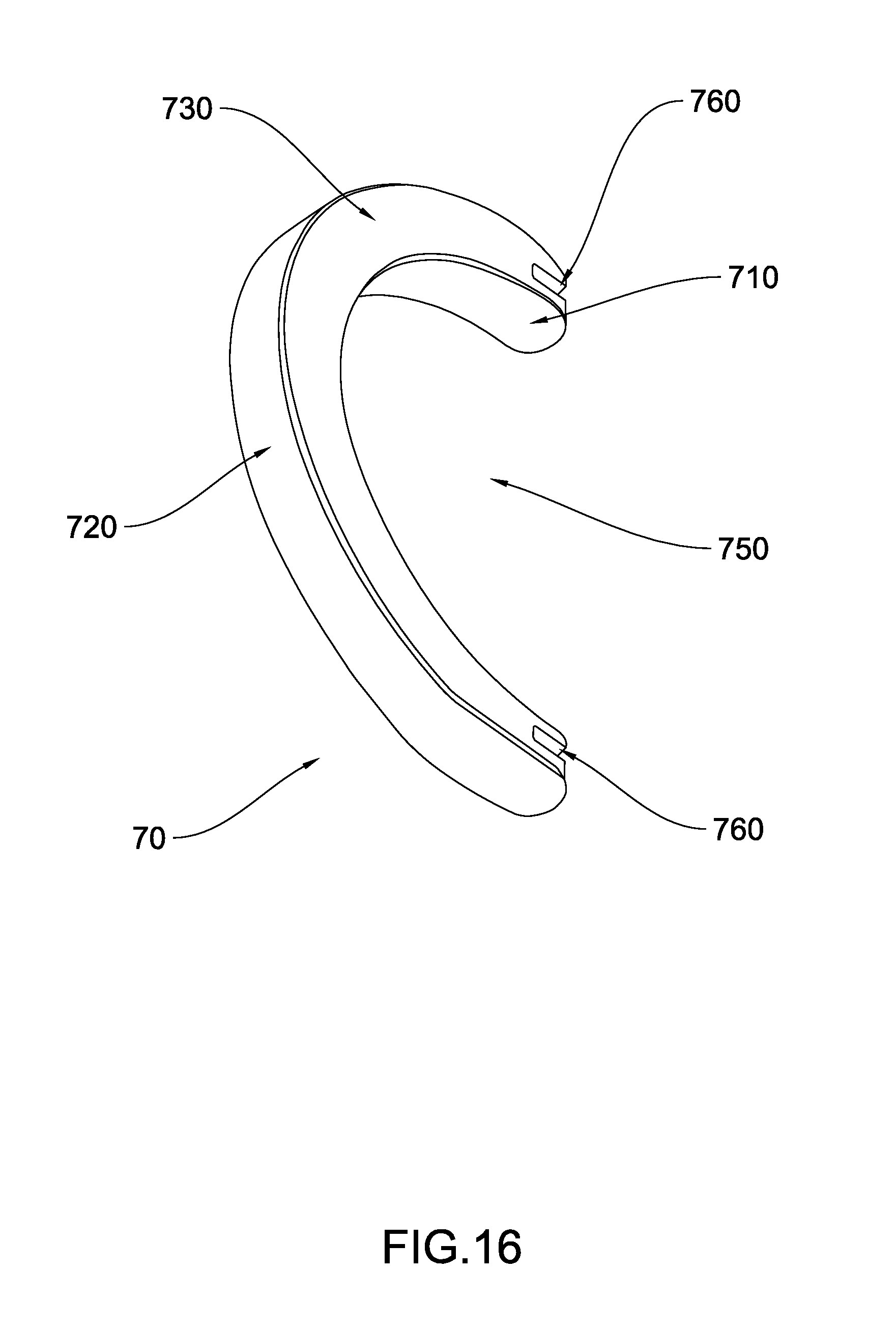
[0030] FIG. 16 is a first perspective view of the auxiliary flipper according to the second preferred embodiment of the present invention, illustrating the different surfaces of the auxiliary flipper.
[0031] FIG. 17 is a second perspective view of the auxiliary flipper according to the second preferred embodiment of the present invention, illustrating the different surfaces of the auxiliary flipper.
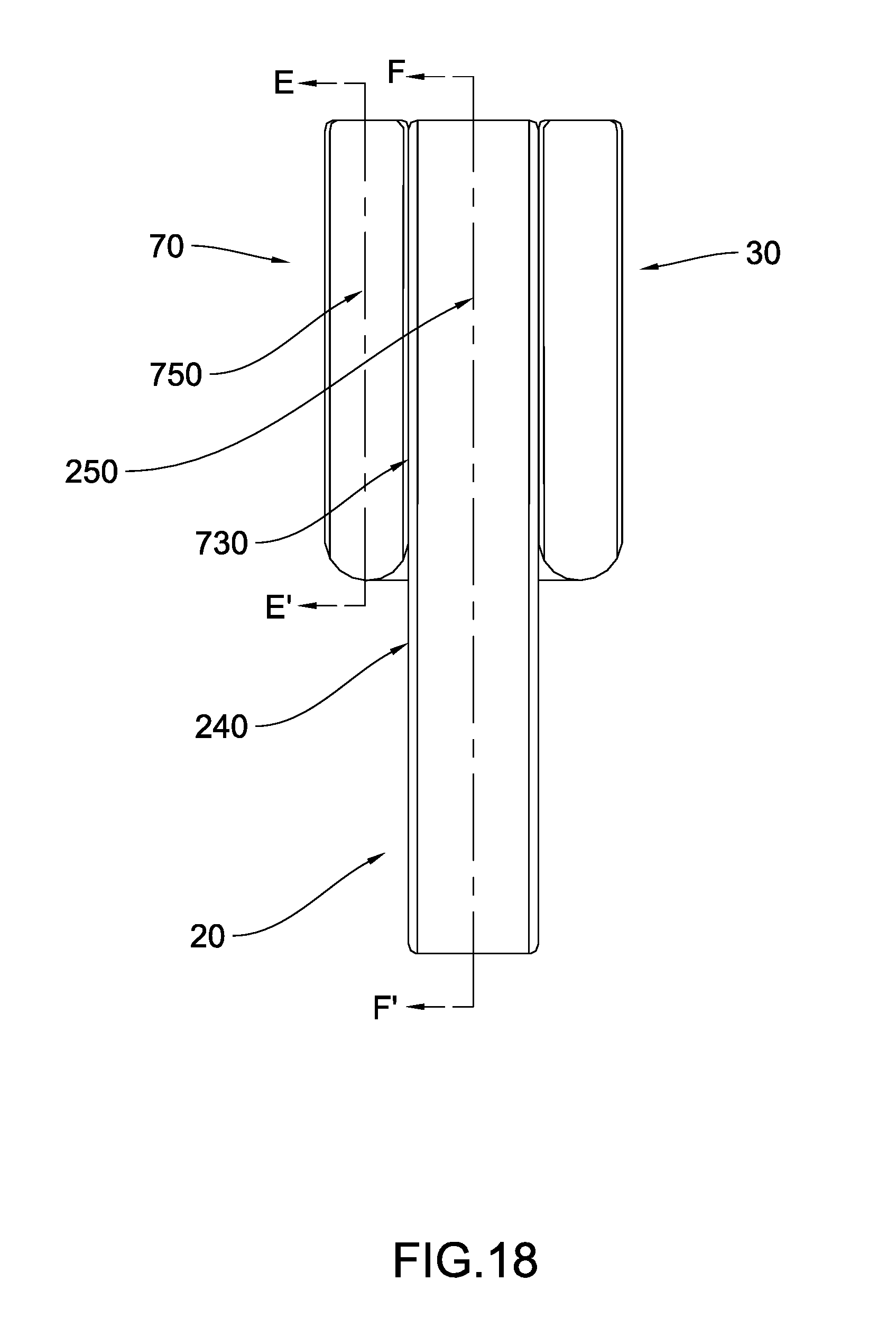
[0032] FIG. 18 is a side view of the foldable ring illustrating the auxiliary flipper in the first position according to the second preferred embodiment of the present invention.
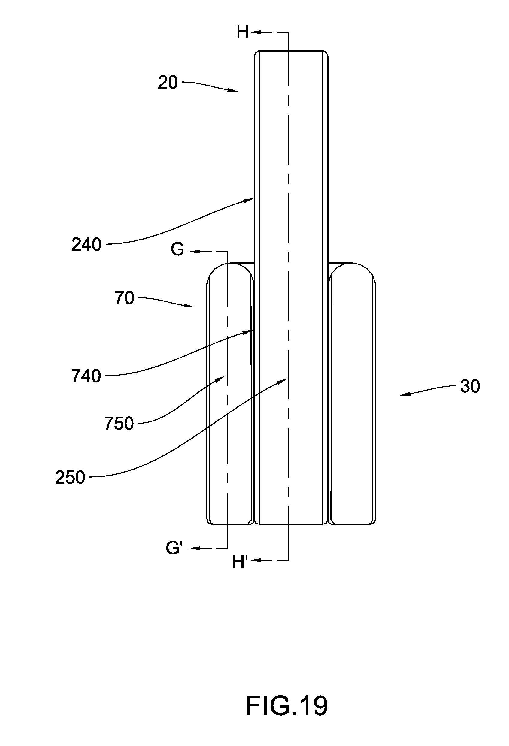
[0033] FIG. 19 is a side view of the foldable ring illustrating the auxiliary flipper in the second position according to the second preferred embodiment of the present invention.
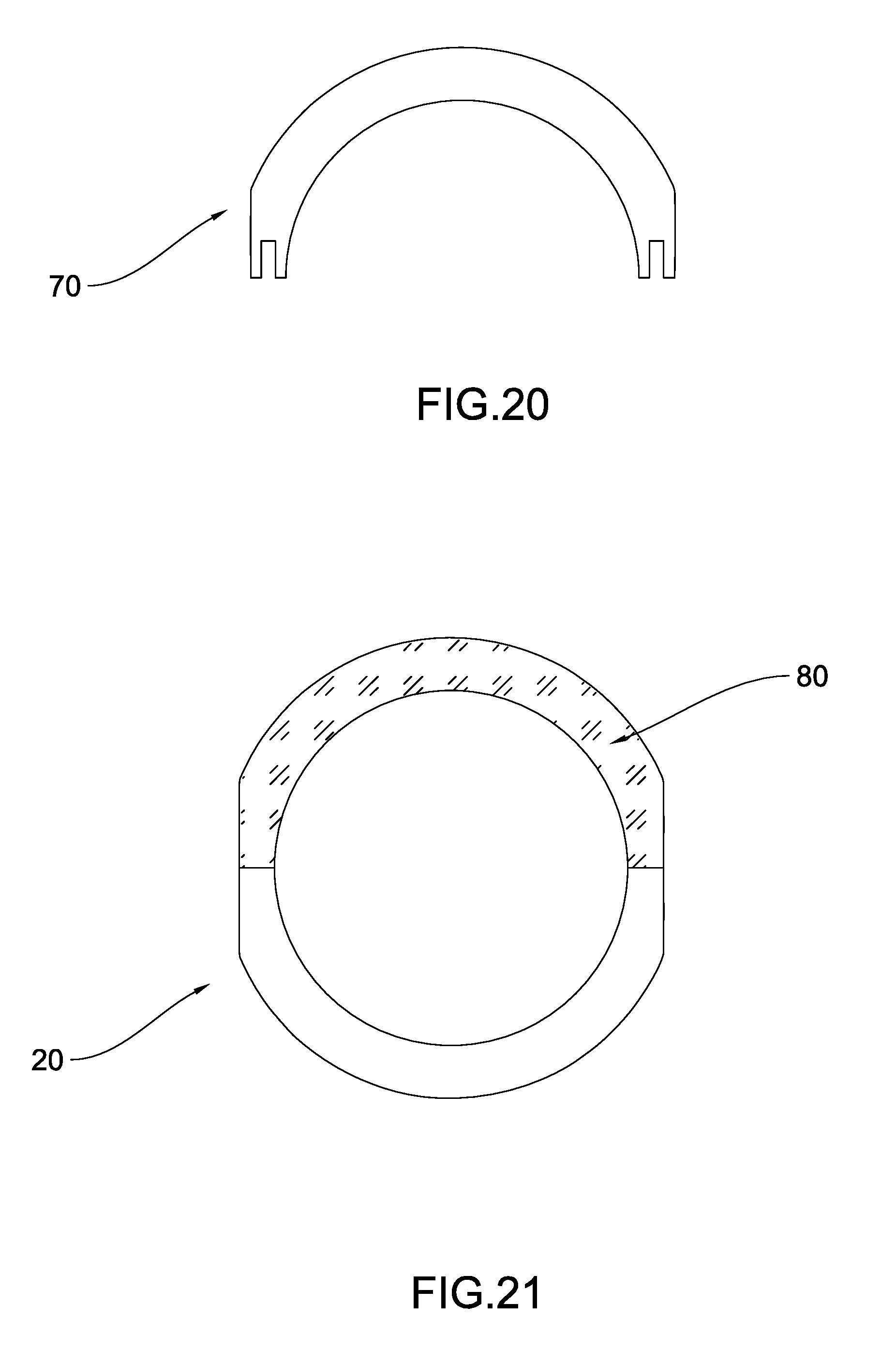
[0034] FIG. 20 is a cross sectional view of section E-E' according to the second preferred embodiment of the present invention illustrating the cross sectional shape of the auxiliary flipper in the first position.
[0035] FIG. 21 is a cross sectional view of section F-F' according to the second preferred embodiment of the present invention illustrating an auxiliary overlapping portion of the main ring when the auxiliary flipper is in the first position.
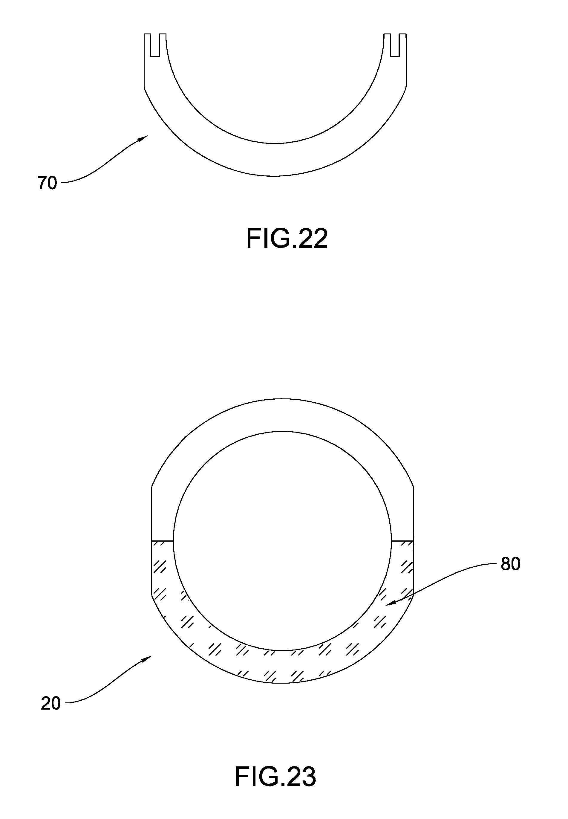
[0036] FIG. 22 is a cross sectional view of section G-G' according to the second preferred embodiment of the present invention illustrating the cross sectional shape of the auxiliary flipper in the second position.
[0037] FIG. 23 is a cross sectional view of section H-H' according to the second preferred embodiment of the present invention illustrating the auxiliary overlapping portion of the main ring when the flipper is in the second position.
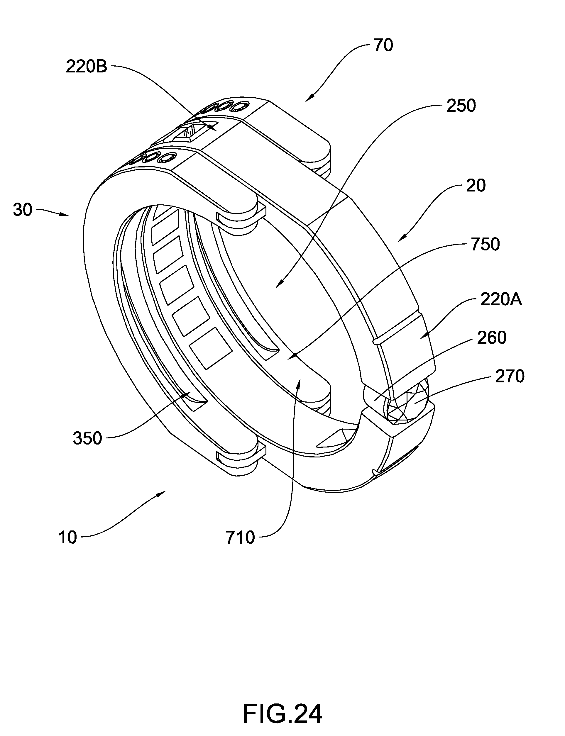
[0038] FIG. 24 is a perspective view of the foldable ring according to the second preferred embodiment of the present invention, illustrating both the flipper and the auxiliary flipper in the first position.
[0039] FIG. 25 is a perspective view of the foldable ring according to the second preferred embodiment of the present invention, illustrating both the flipper and the auxiliary flipper in the second position.
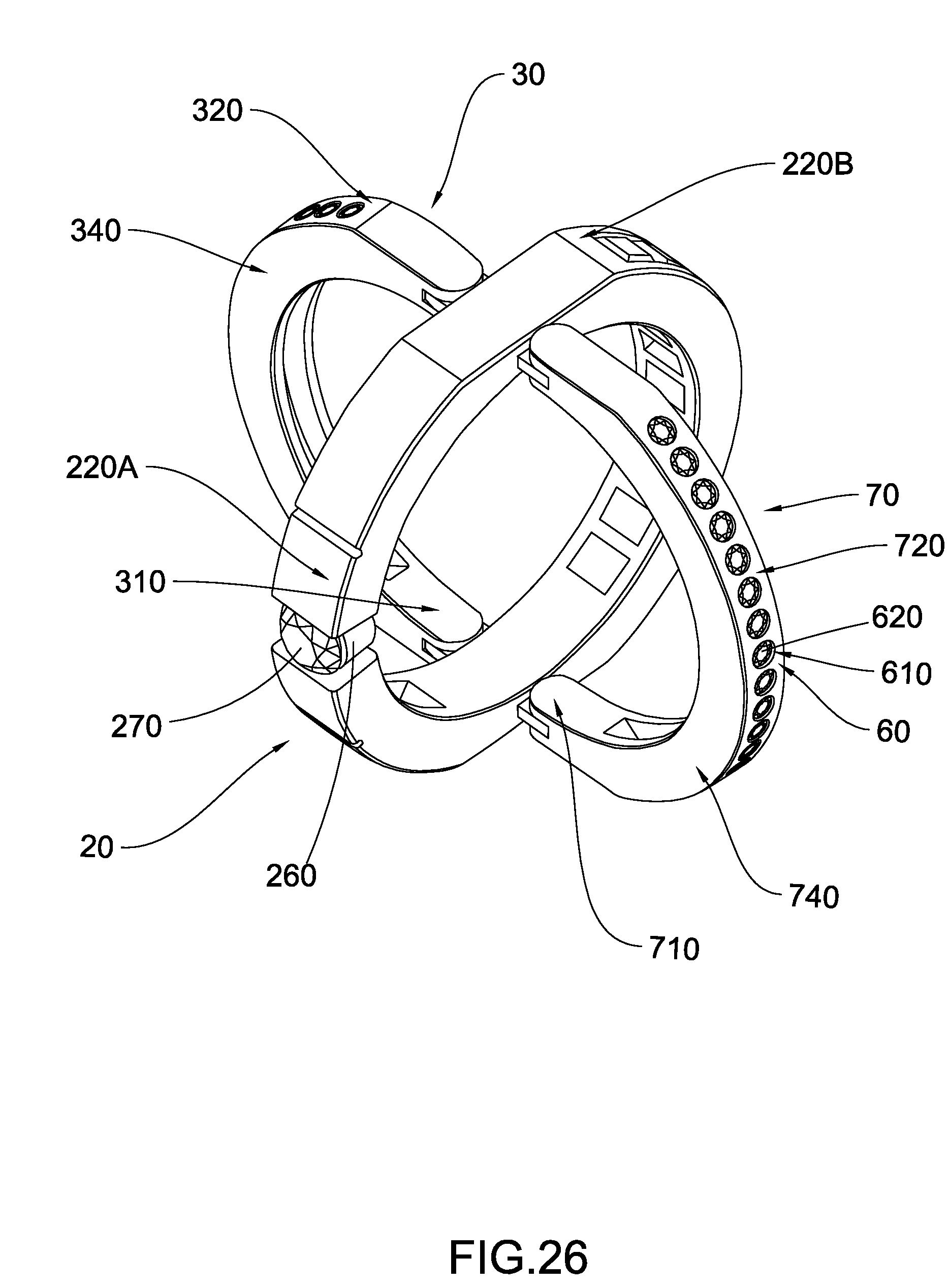
[0040] FIG. 26 is a perspective view of the foldable ring according to the second preferred embodiment of the present invention, illustrating different ornaments being provided on the foldable ring.
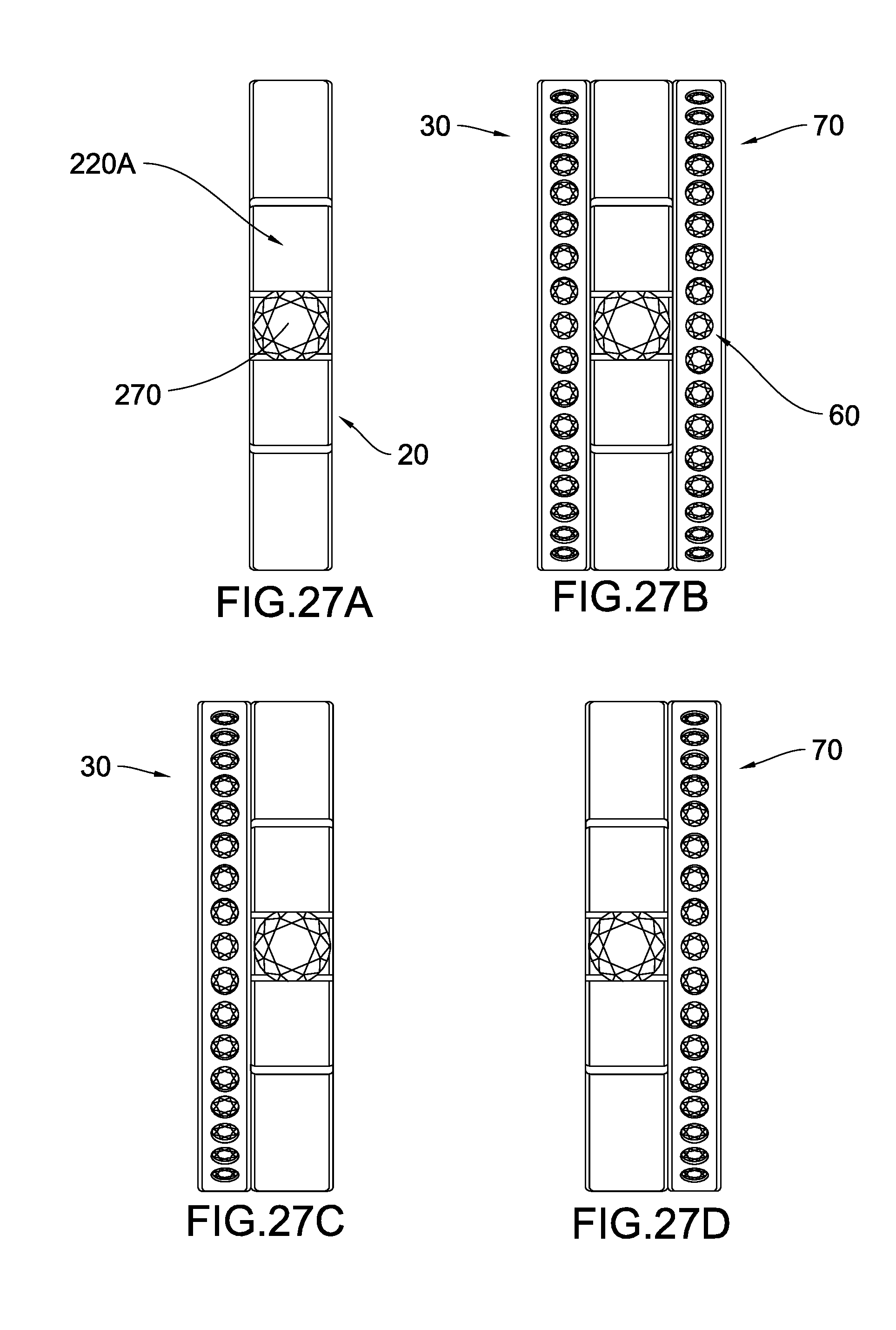
[0041] FIG. 27A-D are aerial views of the foldable ring according to the second preferred embodiment of the present invention, illustrating the four different displays when the first outer surface portion is displayed to the top.
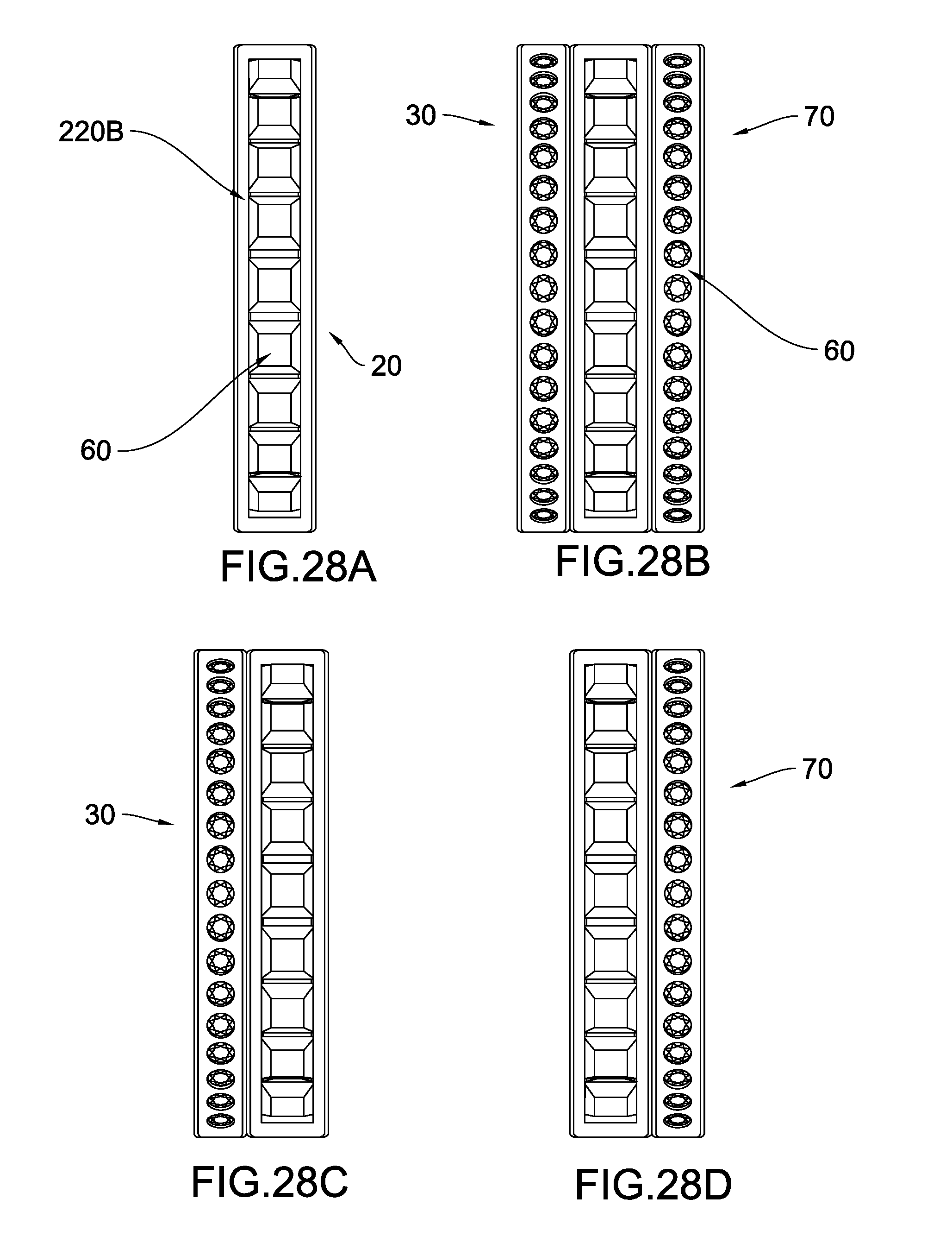
[0042] FIG. 28A-D are aerial views of the foldable ring according to the second preferred embodiment of the present invention, illustrating the four different displays when the second outer surface portion is displayed to the top.
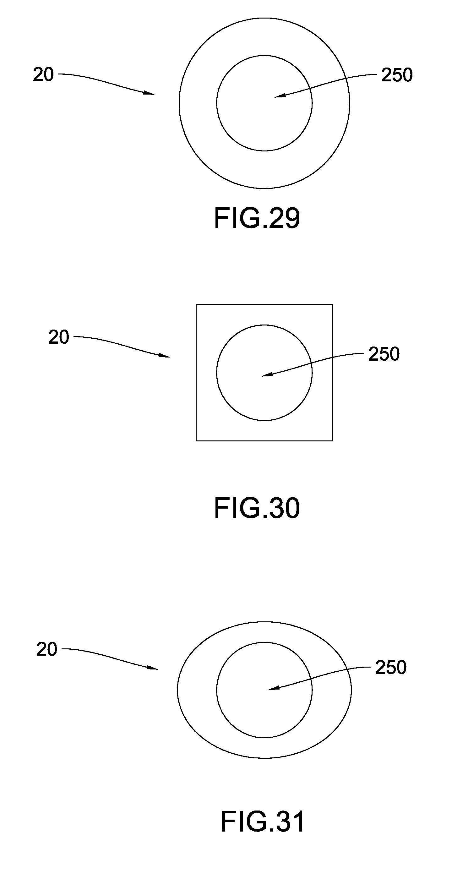
[0043] FIG. 29 is a cross section view of the main ring according to an alternative of the present invention.
[0044] FIG. 30 is a cross section view of the main ring according to an alternative of the present invention.
[0045] FIG. 31 is a cross section view of the main ring according to an alternative of the present invention.
DETAILED DESCRIPTION OF THE PREFERRED EMBODIMENT
[0046] The following detailed description of the preferred embodiment is the preferred mode of carrying out the invention. The description is not to be taken in any limiting sense. It is presented for the purpose of illustrating the general principles of the present invention.
[0047] Referring to FIG. 1 of the drawings, a foldable ring 10 according to the first preferred embodiment of the present invention is illustrated. Broadly, the foldable ring 10 may comprise a main ring 20 and a flipper 30.
[0048] Referring to FIG. 2 and FIG. 3 of the drawings, the main ring 20 according to the first preferred embodiment is illustrated. The main ring 20 may have a first inner peripheral surface 210, a first outer peripheral surface 220, a first front surface 230, a first rear surface 240, and a first through cavity 250 formed as a space surround by the first inner peripheral surface 210.
[0049] Referring to FIG. 4 and FIG. 5 of the drawings, the flipper 30 according to the first preferred embodiment of the present invention is illustrated. The flipper 30 may have a second inner peripheral surface 310, a second outer peripheral surface 320, a second front surface 330, a second rear surface 340, and a second through cavity 350 formed as a space surrounded by the second inner peripheral surface 310.
[0050] Referring to FIG. 6 and FIG. 7 of the drawings respectively, the flipper 30 according to the first preferred embodiment is pivotally attached on the first front surface 230 of the main ring 20 to move between a first position and a second position. In either the first position or the second position, the flipper 30 is arranged to pivotally move to overlap on the first front surface 230 of the main ring 20 and the first through cavity 250 is arranged to align with the second through cavity 350 so as to allow a user's finger to pass through both the main ring 20 and the flipper 30.
[0051] FIG. 8 is a cross sectional view of section A-A' from FIG. 6. Referring to FIG. 8 of the drawings, a cross sectional shape of the flipper 30 in the first position according to the first preferred embodiment of the present invention is illustrated. FIG. 9 is a cross sectional view of section B-B' from FIG. 6. Referring to FIG. 9 of the drawings, a cross sectional shape of the main ring 20 according to the first preferred embodiment of the present invention is illustrated. An overlapping portion 40 is defined as the portion where the second front surface 330 of the flipper 30 overlaps on the first front surface 230 of the main ring 20. The overlapping portion 40 of the main ring 20 in the first position is indicated by the shaded region. FIG. 10 is a cross section view of section C-C' from FIG. 7. Referring to FIG. 10 of the drawings, a cross sectional shape of the flipper 30 in the second position according to the first preferred embodiment of the present invention is illustrated. FIG. 11 is a cross section view of section D-D' from FIG. 7. Referring to FIG. 11 of the drawings, the overlapping portion 40 is defined as the portion where the second rear surface 340 of the flipper 30 overlaps on the first front surface 230 of the main ring 20. The overlapping portion 40 of the main ring 20 in the second position is indicated by the shaded region. According to FIG. 8 to FIG. 11, the cross sectional shape of the flipper 30 is substantially the same as that of the overlapping portion 40 of the main ring 20.
[0052] Referring to FIG. 1 to FIG. 4 of the drawings, the foldable ring 10 according to the first preferred embodiment of the present invention may further comprise a hinge mechanism 50 so that the flipper 30 may be pivotally attached on the first front surface 230 of the main ring 20 to move between the first position and the second position. The hinge mechanism 50 may comprise a connector 510 being protruded from the first front surface 230 which is adapted to fit inside a slot 360 at an end of the flipper 30. The connector 510 further comprises a hole 520. Once the connector 510 engages with the slot 360, a bolt 530 may be inserted in the hole 520 for joining the flipper 30 with then main ring 20 to provide a stable pivotal motion for the flipper 30 to move between the first position and the second position as desired by the user. The hinge mechanism 50 is provided along an axis of symmetry of the main ring 20. As shown in FIG. 12 and FIG. 13 of the drawings, a pair of hinge mechanisms 50 may be provided on the first front surface 230 along the axis of symmetry of the main ring 20.
[0053] Referring to FIG. 12 and FIG. 13 of the drawings, the foldable ring 10 according to the first preferred embodiment of the present invention is illustrated where the flipper 30 is in the first position and the second position respectively. Since the cross sectional shape of the flipper 30 is substantially the same as that of the overlapping portion 40, the first through cavity 250 is arranged to align with the second through cavity 350 so that the user may insert the foldable ring 10 into his/her finger through the first through cavity 250 and the second through cavity 350 in either the first position or the second position. In addition, once the foldable ring 10 is fittedly inserted onto the user's finger, the second inner peripheral surface 310 of the flipper 30 makes contact with the finger and may prevent the flipper 30 from moving out of the first position or the second position. Therefore, it is not necessary to provide a locking mechanism to retain the first or the second position of the flipper 30.
[0054] Referring to FIG. 12 and FIG. 13 of the drawings, the main ring 20 may further comprise a stone setting 260 as a part connecting the main ring 20 for receiving and setting a main ornament stone 270 for decorative purpose. According to the first preferred embodiment of the present invention, the first outer peripheral surface 220 of the main ring 20 may be further divided into a first outer surface portion 220A and a second outer surface portion 220B in such a manner that the first outer surface portion 220A and the second outer surface portion 220B may be divided by a hypothetical line joining the two hinge mechanisms 50. The stone setting 260 and the main ornament stone 270 are provided on the first outer surface portion 220A.
[0055] FIG. 14 of the drawings-illustrates that at least one ornament article 60 is provided on at least one of the first inner peripheral surface 210, the first outer peripheral surface 220, the first front surface 230, the first rear surface 240, the second inner peripheral surface 310, the second outer peripheral surface 320, the second front surface 330, and the second rear surface 340. The ornament article 60 may comprise an engraved slot 610 or a secondary ornamental stone 620 for decorative purpose. Referring to FIG. 14 of the drawings, it can be seen that a plurality of circular engraved slots 610 are carved into the second outer peripheral surface 320 while a plurality of circular secondary ornamental stones 620 such as diamonds are provided inside the circular engraved slots 610. Similarly, a rectangular engraved slot 610 is carved into the second outer surface portion 220B of the first outer peripheral surface 220 while a plurality of rectangular secondary ornamental stones 620 such as gems are provided inside the rectangular engraved slots 610 for decorative purpose.
[0056] Referring to FIG. 15 to FIG. 29 of the drawings, a second preferred embodiment of the present invention is illustrated. The structural and operational relationships between the main ring 20 and flipper 30 remain the same as illustrated above.
[0057] Referring to FIG. 15 of the drawings, the foldable ring 10 according to the second preferred embodiment of the present invention may further comprise an auxiliary flipper 70. Referring to FIG. 16 and FIG. 17 of the drawings, the auxiliary flipper 70 according to the second preferred embodiment of the present invention is illustrated. The auxiliary flipper 70 may have a third inner peripheral surface 710, a third outer peripheral surface 720, a third front surface 730, a third rear surface 740, and a third through cavity 750 formed as a space surrounded by the third inner peripheral surface 710.
[0058] Referring to FIG. 18 and FIG. 19 of the drawings respectively, the auxiliary flipper 70 according to the second preferred embodiment of the present invention is pivotally attached on the first rear surface 240 of the main ring 20 to move between a first position and a second position. In either the first position or the second position, the auxiliary flipper 70 is arranged to pivotally move to overlap on the first rear surface 240 of the main ring 20 and the first through cavity 250 is arranged to align with the third through cavity 750 so as to allow a user's finger to pass through both the main ring 20 and the auxiliary flipper 70.
[0059] FIG. 20 is a cross sectional view of section E-E' from FIG. 18. Referring to FIG. 20 of the drawings, a cross sectional shape of the auxiliary flipper 70 according to the second preferred embodiment of the present invention in the first position is illustrated. FIG. 21 is a cross sectional view of section F-F' from FIG. 18. Referring to FIG. 21 of the drawings, a cross sectional shape of the main ring 20 according to the second preferred embodiment of the present invention is illustrated. An auxiliary overlapping portion 80 is defined as the portion where the third front surface 730 of the auxiliary flipper 70 overlaps on the first rear surface 240 of the main ring 20. The auxiliary overlapping portion 80 of the main ring 20 in the first position is indicated by the shaded region. FIG. 22 is a cross section view of section G-G' from FIG. 19. Referring to FIG. 22 of the drawings, a cross sectional shape of the auxiliary flipper 70 in the second position according to the second preferred embodiment of the present invention is illustrated. FIG. 23 is a cross section view of section H-H' from FIG. 19. Referring to FIG. 23 of the drawings, the auxiliary overlapping portion 80 is defined as the portion where the third rear surface 740 of the auxiliary flipper 70 overlaps on the first rear surface 240 of the main ring 20. The auxiliary overlapping portion 80 of the main ring 20 in the second position is indicated by the shaded region. Referring to FIG. 20 to FIG. 23, the cross sectional shape of the auxiliary flipper 70 is substantially the same as that of the auxiliary overlapping portion 80 of the main ring 20.
[0060] Referring to FIG. 15, FIG. 16 and FIG. 17 of the drawings, the foldable ring 10 according to the second preferred embodiment of the present invention may comprise the hinge mechanism 50 so that the auxiliary flipper 70 may be pivotally attached on the first rear surface 240 of the main ring 20 to move between the first position and the second position. The hinge mechanism 50 may comprise the connector 510 being protruded from the first rear surface 240 which is adapted to fit inside a slot 760 at an end of the auxiliary flipper 70. The connector 510 further comprises the hole 520. Once the connector 510 engages with the slot 760, a bolt 530 may be inserted in the hole 520 for joining the auxiliary flipper 70 and the main ring 20 to provide a stable pivotal motion for the auxiliary flipper 70 to move between the first position and the second position as desired by the user. The hinge mechanism 50 is provided along an axis of symmetry of the main ring 20. As shown in FIG. 24 and FIG. 25 of the drawings, a pair of hinge mechanisms 50 may be provided on the first rear surface 240 along the axis of symmetry of the main ring 20.
[0061] Referring to FIG. 24 and FIG. 25 of the drawings, the foldable ring 10 according to the second preferred embodiment of the present invention is illustrated where both the flipper 30 and the auxiliary flipper 70 are in the first position and the second position respectively. Since the cross sectional shape of the auxiliary flipper 70 is substantially the same as that of the auxiliary overlapping portion 80, the first through cavity 250 is arranged to align with the third through cavity 750 so that the user may insert the foldable ring 10 into his/her finger through the first through cavity 250, the second through cavity 350 and the third through cavity 750 with the flipper 30 and the auxiliary flipper 70 in either the first position or the second position. In addition, once the foldable ring 10 is fittedly inserted onto the user's finger, the third inner peripheral surface 710 of the auxiliary flipper 70 makes contact with the finger and may prevent the auxiliary flipper 70 from moving out of the first position or the second position. Therefore, it is not necessary to provide a locking mechanism to retain the first or the second position of the auxiliary flipper 70.
[0062] Referring to FIG. 24 and FIG. 25 of the drawings, similar to the first preferred embodiment of the present invention, the main ring 20 according to the second preferred embodiment may further comprise the stone setting 260 as a part connecting the main ring 20 for receiving and setting the main ornament stone 270 for display purpose. Similar to the first preferred embodiment of the present invention, the first outer peripheral surface 220 of the main ring 20 may be further divided into the first outer surface portion 220A and the second outer surface portion 220B in such a manner that the first outer surface portion 220A and the second outer surface portion 220B may be divided by a hypothetical line joining the two hinge mechanisms 50. The stone setting 260 and the main ornament stone 270 are provided on the first outer surface portion 220A.
[0063] FIG. 26 of the drawings illustrates that at least one ornament article 60 is provided on at least one of the first inner peripheral surface 210, the first outer peripheral surface 220, the first front surface 230, the first rear surface 240, the second inner peripheral surface 310, the second outer peripheral surface 320, the second front surface 330, the second rear surface 340, the third inner peripheral surface 710, the third outer peripheral surface 720, the third front surface 730, and the third rear surface 740. Referring to FIG. 26 of the drawings, it can be seen that a plurality of circular engraved slots 610 are carved into the third outer peripheral surface 720 while a plurality of secondary ornamental stones 620 such as diamonds are provided inside the engraved slots 610.
[0064] According to the second preferred embodiment of the present invention, the flipper 30 and the auxiliary flipper 70 may operate independently with respect to each other. Since the user may select to flip the flipper 30 or the auxiliary flipper 70 to either the first position or the second position, there are a total of four different combinations. Referring to FIG. 26 of the drawings, the foldable ring 10 according to the second preferred embodiment of the present invention may be worn by the user to display either the first outer surface portion 220A or the second outer surface portion 220B to the top. From an aerial view, the foldable ring 10 may provide a total of eight different displays when worn by the user. FIG. 27A is an aerial view of the foldable ring 10 displaying the first outer surface portion 220A to the top with both the flipper 30 and auxiliary flipper 70 in the first position. When the foldable ring 10 in this configuration is worn by the user's finger, both the flipper 30 and the auxiliary flipper 70 cannot be seen from the aerial view. FIG. 27B is an aerial view of the foldable ring 10 displaying the first outer surface portion 220A to the top with both the flipper 30 and auxiliary flipper 70 in the second position. FIG. 27C is an aerial view of the foldable ring 10 displaying the first outer surface portion 220A to the top with the flipper 30 in the second position and the auxiliary flipper 70 in the first position. FIG. 27D is an aerial view of the foldable ring 10 displaying the first outer surface portion 220A to the top with the flipper 30 in the first position and the auxiliary flipper 70 in the second position. FIG. 28A is an aerial view of the foldable ring 10 displaying the second outer surface portion 220B to the top with both the flipper 30 and auxiliary flipper 70 in the second position. FIG. 28B is an aerial view of the foldable ring 10 displaying the second outer surface portion 220B to the top with both the flipper 30 and auxiliary flipper 70 in the first position. FIG. 28C is an aerial view of the foldable ring 10 displaying the second outer surface portion 220B to the top with the flipper 30 in the first position and the auxiliary flipper 70 in the second position. FIG. 28D is an aerial view of the foldable ring 10 displaying the second outer surface portion 220B to the top with the flipper 30 in the second position and the auxiliary flipper 70 in the first position.
[0065] FIG. 29 of the drawings illustrates that the main ring 20 may have a substantially circular cross sectional shape as an alternative. The cross sectional shape is viewed from the first front surface 230 through the first through cavity 250. Similarly, FIG. 30 and FIG. 31 of the drawings illustrate that the main ring 20 may have a substantially quadrilateral or elliptical cross sectional shape respectively as alternatives.
[0066] The present invention, while illustrated and described in terms of different preferred embodiments, is not limited to the particular description contained in this specification. Additional alternative or equivalent components could also be used to practice the present invention.
* * * * *
D00000
D00001
D00002
D00003
D00004
D00005
D00006
D00007
D00008
D00009
D00010
D00011
D00012
D00013
D00014
D00015

D00016
D00017
D00018
D00019
D00020
D00021

D00022
D00023
D00024
D00025
XML
uspto.report is an independent third-party trademark research tool that is not affiliated, endorsed, or sponsored by the United States Patent and Trademark Office (USPTO) or any other governmental organization. The information provided by uspto.report is based on publicly available data at the time of writing and is intended for informational purposes only.
While we strive to provide accurate and up-to-date information, we do not guarantee the accuracy, completeness, reliability, or suitability of the information displayed on this site. The use of this site is at your own risk. Any reliance you place on such information is therefore strictly at your own risk.
All official trademark data, including owner information, should be verified by visiting the official USPTO website at www.uspto.gov. This site is not intended to replace professional legal advice and should not be used as a substitute for consulting with a legal professional who is knowledgeable about trademark law.