Aerosol Generating Article With Ventilation Zone
CARRARO; Andrea ; et al.
U.S. patent application number 16/066179 was filed with the patent office on 2019-01-17 for aerosol generating article with ventilation zone. This patent application is currently assigned to Philip Morris Products S.A.. The applicant listed for this patent is Philip Morris Products S.A.. Invention is credited to Rui Nuno BATISTA, Andrea CARRARO.
| Application Number | 20190014813 16/066179 |
| Document ID | / |
| Family ID | 55027621 |
| Filed Date | 2019-01-17 |


| United States Patent Application | 20190014813 |
| Kind Code | A1 |
| CARRARO; Andrea ; et al. | January 17, 2019 |
AEROSOL GENERATING ARTICLE WITH VENTILATION ZONE
Abstract
An aerosol generating article is provided, including a combustible heat source; an aerosol forming substrate downstream of the combustible heat source; and a wrapper circumscribing at least a rear portion of the combustible heat source and at least a front portion of the aerosol forming substrate, wherein a plurality of weakness formations are provided on a region of the wrapper overlying the combustible heat source, and wherein the wrapper is rupturable at the plurality of weakness formations and is configured to form a ventilation zone comprising a plurality of apertures extending through the wrapper.
| Inventors: | CARRARO; Andrea; (Ins, CH) ; BATISTA; Rui Nuno; (Morges, CH) | ||||||||||
| Applicant: |
|
||||||||||
|---|---|---|---|---|---|---|---|---|---|---|---|
| Assignee: | Philip Morris Products S.A. Neuchatel CH |
||||||||||
| Family ID: | 55027621 | ||||||||||
| Appl. No.: | 16/066179 | ||||||||||
| Filed: | December 19, 2016 | ||||||||||
| PCT Filed: | December 19, 2016 | ||||||||||
| PCT NO: | PCT/EP2016/081783 | ||||||||||
| 371 Date: | June 26, 2018 |
| Current U.S. Class: | 1/1 |
| Current CPC Class: | A24F 47/006 20130101; A24D 3/043 20130101; A24D 1/025 20130101; A24D 1/02 20130101; A24D 1/027 20130101 |
| International Class: | A24D 1/02 20060101 A24D001/02; A24F 47/00 20060101 A24F047/00 |
Foreign Application Data
| Date | Code | Application Number |
|---|---|---|
| Dec 31, 2015 | EP | 15203245.4 |
Claims
1.-16. (canceled)
17. An aerosol generating article, comprising: a combustible heat source; an aerosol forming substrate downstream of the combustible heat source; and a wrapper circumscribing at least a rear portion of the combustible heat source and at least a front portion of the aerosol forming substrate, wherein a plurality of weakness formations are provided on a region of the wrapper overlying the combustible heat source, and wherein the wrapper is rupturable at the plurality of weakness formations and is configured to form a ventilation zone comprising a plurality of apertures extending through the wrapper.
18. The aerosol generating article according to claim 17, wherein at least one of the weakness formations is defined by one or more lines of weakness.
19. The aerosol generating article according to claim 17, wherein at least one of the weakness formations is defined by two or more intersecting lines of weakness.
20. The aerosol generating article according to claim 17, wherein the plurality of weakness formations are formed from a local reduction in thickness of the wrapper.
21. The aerosol generating article according to claim 17, wherein each weakness formation of the plurality of weakness formations has a circumferential dimension of at least about 0.5 mm.
22. The aerosol generating article according to claim 17, wherein each weakness formation of the plurality of weakness formations has a circumferential dimension of from about 0.5 mm to about 2.6 mm.
23. The aerosol generating article according to claim 17, wherein each weakness formation of the plurality of weakness formations has a circumferential dimension of from about 0.8 mm to about 1.8 mm.
24. The aerosol generating article according to claim 17, wherein each weakness formation of the plurality of weakness formations has a length of at least about 0.1 mm.
25. The aerosol generating article according to claim 17, wherein each weakness formation of the plurality of weakness formations has a length of from about 0.1 mm to about 2.1 mm.
26. The aerosol generating article according to claim 17, wherein each weakness formation of the plurality of weakness formations has a length of from about 0.2 mm to about 1.8 mm.
27. The aerosol generating article according to claim 17, wherein adjacent weakness formations among the plurality of weakness formations are separated in a circumferential direction by a circumferential separation of at least about 0.5 mm.
28. The aerosol generating article according to claim 17, wherein adjacent weakness formations among the plurality of weakness formations are separated in a longitudinal direction by a longitudinal separation of at least about 0.4 mm.
29. The aerosol generating article according to claim 17, wherein the plurality of weakness formations are provided in a regular pattern.
30. The aerosol generating article according to claim 17, wherein the plurality of weakness formations are arranged such that the plurality of apertures have a total area of at least about 0.09 millimetres squared.
31. The aerosol generating article according to claim 17, wherein the weakness formations of the plurality of weakness formations are arranged such that the plurality of apertures form indicia on an outer surface of the wrapper.
32. The aerosol generating article according to claim 17, wherein the wrapper is formed from a heat conductive material.
33. The aerosol generating article according to claim 17, wherein the wrapper is substantially impermeable to air.
34. The aerosol generating article according to claim 17, wherein the wrapper circumscribes the combustible heat source along at least about 50 percent of a length of the combustible heat source.
35. The aerosol generating article according to claim 34, wherein the weakness formations of the plurality of weakness formations are provided on the wrapper such that a ventilation zone extends along at least about 50 percent of the length of the combustible heat source.
36. The aerosol generating article according to claim 17, wherein the wrapper is in direct contact with an outer surface of the combustible heat source.
Description
[0001] The present invention relates to an aerosol generating article, such as a heated smoking article. In particular, examples of the present invention relate to an aerosol generating article comprising a combustible heat source, an aerosol-forming substrate downstream of the combustible heat source and a wrapper circumscribing at least a rear portion of the combustible heat source and at least a front portion of the aerosol-forming substrate.
[0002] A number of smoking articles in which tobacco is heated rather than combusted have been proposed in the art. An aim of such `heated` smoking articles is to reduce known harmful smoke constituents of the type produced by the combustion and pyrolytic degradation of tobacco in conventional cigarettes. In one known type of heated smoking article, an aerosol is generated by the transfer of heat from a combustible heat source to a physically separate aerosol-forming substrate located downstream of the combustible heat source. During smoking, volatile compounds are released from the aerosol-forming substrate by heat transfer from the combustible heat source and entrained in air drawn through the smoking article. As the released compounds cool, they condense to form an aerosol that is inhaled by the user.
[0003] It is known to include a heat-conducting element around at least a rear portion of the combustible heat source and at least a front portion of the aerosol-forming substrate of the heated smoking article in order to ensure conductive heat transfer from the combustible heat source to the aerosol-forming substrate to obtain an aerosol. For example, WO-A2-2009/022232 discloses a smoking article comprising a combustible heat source, an aerosol-forming substrate downstream of the combustible heat source, and a heat-conducting element around and in direct contact with a rear portion of the combustible heat source and an adjacent front portion of the aerosol-forming substrate. The heat-conducting element and the aerosol-forming substrate are circumscribed by an outer wrapper of paper. In use, the front portion of the aerosol-forming substrate is heated by conduction through the abutting rear portion of the combustible heat source and the heat-conducting element.
[0004] In smoking articles in which tobacco is heated rather than combusted, the temperature attained in the aerosol-forming substrate has a significant impact on the ability to generate a sensorially acceptable aerosol. It is typically desirable to maintain the temperature of the aerosol-forming substrate within a certain range in order to optimise the aerosol delivery to a user. In smoking articles comprising a combustible heat source and an aerosol-forming substrate located downstream of the combustible heat source, movement of the combustible heat source relative to the aerosol-forming substrate during use of the smoking article may cause the temperature of the aerosol-forming substrate to drop outside of a desired range, thereby impacting the performance of the smoking article. If the temperature of the aerosol-forming substrate drops too low, for instance, it may adversely impact the consistency and the amount of aerosol delivered to a user.
[0005] A number of ways of retaining combustible heat sources in position within heated smoking articles have been proposed. For example, it is known to apply a layer of glue around the combustible heat source, between the combustible heat source and the wrapper. However, if the glue is combusted during use, the combustible heat source may be held in place only by the wrapper. This may lead to movement of the combustible heat source relative to the aerosol forming substrate if the holding force applied by the wrapper is insufficient.
[0006] It has also been proposed to wrap the wrapper tightly around the combustible heat source, or to extend the wrapper such that it circumscribes the entire length of the combustible heat source. However, in both cases, the wrapper may adversely affect combustion of the heat source by restricting the air supply, which may lead to a drop in the temperature of the aerosol-forming substrate and an adverse impact on the consistency and the amount of aerosol delivered to a user. Additionally, the pressure generated by combustion gases produced by the combustible heat source may build up behind a tightly wrapped wrapper. This may lead to the creation of an air gap between the combustible heat source and the wrapper, reducing the holding force applied during use by the wrapper and possibly leading to movement of the combustible heat source relative to the aerosol forming substrate. Where the wrapper comprises a heat conducting element, air gaps between the combustible heat source and the wrapper may adversely affect conductive heat transfer from the combustible heat source to the aerosol forming substrate by the heat conducting element and hence the performance of the smoking article. In some cases, pressure generated by combustion gases behind a tightly wrapped wrapper may be sufficient to damage the wrapper or the combustible heat source.
[0007] It would be desirable to provide an aerosol generating article in which retention of the combustible heat source is improved preferably with no or low adverse impact on conductive heat transfer from the combustible heat source to the aerosol-forming substrate and hence on the performance of the aerosol generating article.
[0008] According to a first aspect of the present invention, there is provided an aerosol generating article comprising: a combustible heat source; an aerosol forming substrate downstream of the combustible heat source; a wrapper circumscribing at least a rear portion of the combustible heat source and at least a front portion of the aerosol forming substrate; wherein a plurality of weakness formations are provided on a region of the wrapper overlying the combustible heat source, and wherein the wrapper is rupturable during use at the plurality of weakness formations to form a ventilation zone comprising a plurality of apertures extending through the wrapper.
[0009] Advantageously, with this arrangement, the wrapper can be applied tightly around the combustible heat source to hold it in the correct position while still allowing a sufficient supply of air to the combustible heat source and allowing combustion gases generated by the heat source to escape through the plurality of apertures during use. This ensures that the conductive heat transfer from the heat source to the aerosol forming substrate, and consequently the performance of the aerosol generating article, is maintained. It may also remove the need for glue to be applied around the combustible heat source, simplifying manufacture. In some examples, the weakness formations are arranged such that the wrapper ruptures at the weakness formations for example under the pressure generated by combustion gases. This advantageously allows the combustible heat source to be ventilated during use without undue burden on the user. Additionally, by providing weakness formations at which the wrapper is rupturable to form a plurality of apertures, the wrapper forms a barrier prior to rupture, for example to restrict the amount of moisture absorbed from the atmosphere by the heat source during transportation and storage. As moisture may hinder the heating performance of the heat source, restricting the amount of moisture absorbed by the heat source may have a positive impact on the performance of the aerosol generating article.
[0010] As used herein, the term "weakness formations" refers to structural weaknesses in the wrapper arranged to facilitate tearing or breakage of the wrapper at predefined positions to form apertures with predefined shapes and dimensions. The structural weaknesses may be formed for example through removal or destruction of some of the material in that portion for example laser ablation or other method, or through mechanical pressing or rolling without removing material. The term "weakness formations" includes lines of weakness, along which the wrapper material has been weakened, and areas of weakness across which the wrapper material has been removed.
[0011] As used herein, the terms `upstream` and `front`, and `downstream` and `rear`, are used to describe the relative positions of components, or portions of components, of the aerosol generating article in relation to the direction in which air flows through the aerosol generating article during use thereof. Aerosol generating articles according to the invention comprise a proximal end through which, in use, an aerosol exits the article for delivery to a user. The proximal end of the aerosol generating article may also be referred to as the mouth end or the downstream end. In use, a user draws on the mouth end of the aerosol generating article. The mouth end is downstream of the distal end. The combustible heat source is located at or proximate to the distal end. The distal end of the aerosol generating article may also be referred to as the upstream end. Components, or portions of components, of the smoking article may be described as being upstream or downstream of one another based on their relative positions between the proximal end of the smoking article and the distal end of the smoking article. The front of a component, or portion of a component, of the aerosol generating article is the portion at the end closest to the upstream end of the aerosol generating article. The rear of a component, or portion of a component, of the aerosol generating article is the portion at the end closest to the downstream end of the aerosol generating article. The rear portion of the combustible heat source is the portion of the combustible heat source at the downstream end of the combustible heat source. The front portion of the aerosol forming substrate is the portion of the aerosol forming substrate at the upstream end of the aerosol forming substrate.
[0012] In certain preferred embodiments, at least one of the weakness formations is defined by one or more lines of weakness. The plurality of weakness formations may each be defined by one or more lines of weakness. The weakness formations may be defined by an area of weakness, for example an area of the wrapper having a local reduction in thickness. At least one of the weakness formations may be defined by a single line of weakness extending along the perimeter, or part of the perimeter, of the desired aperture shape. In such examples, the line of weakness may have any suitable shape, for example a straight line, a curved or uneven line, a closed shape, or any combination thereof. In other examples, at least one of the weakness formations may be defined by two or more lines of weakness. The two or more lines of weakness may extend along the perimeter, or part of the perimeter, of the desired aperture shape. The two or more lines of weakness may combine to define the perimeter, or part of the perimeter, of the desired aperture shape. At least one of the weakness formations may be defined by a plurality of lines of weakness that diverge from an unweakened central region.
[0013] Where at least one of the weakness formations is defined by two or more lines of weakness, the two or more lines of weakness may have substantially the same dimensions. The dimensions of one or more of the two or more lines of weakness may be different.
[0014] Where at least one of the weakness formations is defined by one or more lines of weakness, the one or more lines of weakness preferably do not extend through the thickness of the wrapper. With such an arrangement, the wrapper may form a barrier prior to rupture, even in the regions defined by the weakness formation.
[0015] As used herein, the term "line of weakness" refers to a line in the wrapper along which the wrapper material has been weakened to facilitate tearing or breakage of the wrapper along a desired line.
[0016] In certain preferred embodiments, at least one of the weakness formations is defined by two or more intersecting lines of weakness. This may allow a sufficiently large aperture to be defined by the lines of weakness without significantly impacting on the strength of the wrapper prior to use of the aerosol generating article. The plurality of weakness formations may each be defined by two or more intersecting lines. In such examples, the lines of weakness may have any suitable shape, for example a straight line, a curved or uneven line, a closed shape, or any combination thereof. The two or more intersecting lines may intersect each other at any suitable position along their respective lengths. This may depend on the desired shape of aperture to be formed by the rupture of the wrapper at the weakness formation. Preferably, the two or more intersecting lines of weakness are arranged such that the resulting weakness formation has an open shape. That is, the two or more intersecting lines do not combine to completely enclose any part of the wrapper. With this arrangement, the ruptured portions of wrapper may remain connected to the aerosol generating article after the plurality of apertures have been formed. By this, the creation of debris can be avoided.
[0017] The plurality of weakness formations may be formed from a local reduction in thickness of the wrapper. In such embodiments, the local reduction in thickness may be achieved through removal of material, such as by laser ablation. The local reduction in thickness may be achieved through mechanical deformation of the wrapper, such as by rolling or scoring.
[0018] The weakness formations may be defined by a plurality of perforations.
[0019] The weakness formations may have any suitable dimensions.
[0020] In certain embodiments, one or more of the weakness formations may have a circumferential dimension of at least about 0.5 mm, preferably from about 0.5 mm to about 2.6 mm, more preferably from about 0.8 mm to about 1.8 mm. Preferably, each of the weakness formations has a circumferential dimension of at least about 0.5 mm, preferably from about 0.5 mm to about 2.6 mm, more preferably from about 0.8 mm to about 1.8 mm.
[0021] In certain embodiments, one or more of the weakness formations may have a length of at least about 0.1 mm, preferably from about 0.1 mm to about 2.1 mm, more preferably from about 0.2 mm to about 1.8 mm. Preferably, each weakness formation has a length of at least about 0.1 mm, preferably from about 0.1 mm to about 2.1 mm, more preferably from about 0.2 mm to about 1.8 mm.
[0022] Preferably the length of each weakness formation is less than its circumferential dimension. This may help to improve the resistance of the wrapper to rupture due to tension in the circumferential direction of the wrapper in comparison to a weakness formation having a length which is greater than its circumferential dimension.
[0023] The weakness formations may be separated in the circumferential direction by any suitable circumferential separation. In certain embodiments, adjacent weakness formations are separated in the circumferential direction by a circumferential separation of at least about 0.5 mm, preferably from about 0.5 mm to about 2.5 mm, more preferably from about 0.7 mm to about 1.5 mm.
[0024] The weakness formations may be separated in the longitudinal direction by any suitable longitudinal separation. In certain embodiments, adjacent weakness formations are separated in the longitudinal direction by a longitudinal separation of at least about 0.4 mm, preferably from about 0.4 mm to about 1.8 mm, more preferably from about 0.5 mm to about 1.3 mm.
[0025] As used herein, the terms "circumferential separation" and "longitudinal separation" are used to denote the minimum distance between two adjacent weakness formations in the circumferential direction and in the longitudinal direction, respectively.
[0026] The plurality of weakness formations may be arranged in an irregular manner. In certain preferred embodiments, the plurality of weakness formations are provided in a regular pattern. With this arrangement, when the wrapper is ruptured along the plurality of weakness formations, the resulting plurality of apertures are arranged in a regular pattern. This advantageously may lead to homogeneous venting of the combustible heat source. Homogeneous venting of the combustible heat source may prevent sharp localised increases in gas pressure. It may also prevent sharp localised increases in heat source temperature.
[0027] As used herein, the term "regular pattern" is used to denote a pattern comprising a consistently spaced array of weakness formations. For example, the weakness formations may be provided on the wrapper in a regular striped pattern, a regular checked or square pattern, a regular brick pattern, a regular dotted or spotted pattern, a regular honeycomb or hexagonal pattern or any other regular alphanumeric, pictographic or geometric pattern.
[0028] In certain preferred embodiments, the plurality of weakness formations are arranged such that the plurality of apertures have a total area of at least about 0.09 millimetres squared, preferably from about 0.09 millimetres squared to about 40 millimetres squared, more preferably from about 0.4 millimetres squared to about 30 millimetres squared. This arrangement has been found to provide sufficient venting of the combustible heat source without having a significant impact on the strength of the wrapper.
[0029] In certain embodiments, the weakness formations may be arranged such that the plurality of apertures form visible indicia on an outer surface of the wrapper. As used herein, the term "visible indicia" refers to a discrete element, or repeating elements or patterns that provide an aesthetically pleasing, or informative, representation. The indicia may be in the form of text, images, letters, words, logos, or a combination thereof. The indicia may comprise a brand or manufacturer logo that allows the consumer to identify the type or origin of the aerosol-generating article. The indicia may provide information to the user, for example informing the user that the aerosol generating article is ready for use. Light emitted from the combustible heat source during use may be visible through the plurality of apertures. This may increase the visibility of the indicia.
[0030] The wrapper may comprise any suitable material. In certain embodiments, the wrapper may comprise a heat conductive material. The wrapper may be formed from a heat conductive material. In such embodiments, the wrapper may form a heat conducting element extending between the combustible heat source and the aerosol forming substrate. The heat conducting element improves conductive heat transfer from the combustible heat source to the aerosol forming substrate.
[0031] As used herein, the term "heat conductive material" is used to describe a material having a bulk thermal conductivity of at least about 10 W per metre Kelvin (W/(m K)) at 23 degrees Celsius and a relative humidity of 50 percent as measured using the modified transient plan source (MTPS) method. In preferred embodiments, the wrapper is formed from a heat conductive material having a bulk thermal conductivity of at least about 50 W per metre Kelvin, more preferably at least about 100 W per metre Kelvin, most preferably at least about 150 W per metre Kelvin.
[0032] The wrapper may be air restricting prior to rupture of the weakness formations. In other words, the wrapper may inhibit or resist the passage of air through the wrapper prior to use.
[0033] In certain preferred embodiments, the wrapper is substantially impermeable to air. That is, the wrapper is formed from one or more materials that are substantially impermeable to air. With such an arrangement, the wrapper forms a substantially airtight barrier around the combustible heat source. This may substantially prevent absorption of moisture from the atmosphere by the combustible heat source through the wrapper.
[0034] The wrapper circumscribes at least a rear portion of the combustible heat source. Preferably, the wrapper circumscribes the combustible heat source along at least about 50 percent of the length of the combustible heat source. For example, the wrapper may circumscribe the combustible heat source along at least about 60 percent of the length of the combustible heat source, at least about 70 percent of the length of the combustible heat source, at least about 80 percent of the length of the combustible heat source, or at least about 90 percent of the length of the combustible heat source. By extending along a greater amount of the length of the combustible heat source, the wrapper may mechanically protect the combustible heat source and may retain the combustible heat source in position relative to the aerosol forming substrate. Due to the presence of the weakness formations at which the wrapper is rupturable during use to form a ventilation zone comprising a plurality of apertures extending through the wrapper, the wrapper can extend further along the length of the combustible heat source than might otherwise be possible without adversely effecting the performance of the aerosol generating article.
[0035] Where the wrapper circumscribes the combustible heat source along at least about 50 percent of the length of the combustible heat source, the ventilation zone may extend along less than 50 percent of the length of the combustible heat source. In preferred embodiments in which the wrapper circumscribes the combustible heat source along at least about 50 percent of the length of the combustible heat source, the weakness formations are provided on the wrapper such that the ventilation zone also extends along at least about 50 percent of the length of the combustible heat source.
[0036] In any of the above embodiments, the weakness formations may be provided on the wrapper such that the ventilation zone extends along substantially the entire length of the region of the wrapper overlying the combustible heat source.
[0037] The wrapper may be in indirect contact with an outer surface of the combustible heat source via one or more intermediate components. The wrapper may be in direct contact with an outer surface of the combustible heat source. The wrapper may be in direct contact with the outer surface of the combustible heat source along substantially the entire length of the region of the wrapper overlying the combustible heat source.
[0038] As used herein, the terms `longitudinal` and `axial` are used to describe the direction between the opposed upstream and downstream ends of the aerosol generating article, or of a component of the aerosol generating article.
[0039] As used herein, the term `length` is used to describe the maximum dimension in the longitudinal direction of a component of the aerosol generating article, such as the combustible heat source, or of the aerosol generating article itself. That is, the maximum dimension in the direction between the opposed upstream and downstream ends of the component, or of the aerosol generating article itself.
[0040] As used herein, the terms `radial` and `transverse` are used to describe the direction perpendicular to the longitudinal direction. That is, the direction perpendicular to the direction between the opposed upstream and downstream ends of a component of the aerosol generating article, such as the combustible heat source, or of the aerosol generating article itself.
[0041] As used herein, the terms "inner surface" and "outer surface" refer to the radially inner and radially outer surfaces, respectively, of a component of the aerosol generating article.
[0042] As used herein, the term `diameter` denotes the maximum dimension in the transverse direction of a component of the aerosol generating article, such as the combustible heat source, or of the aerosol generating article itself.
[0043] Aerosol generating articles according to the present invention comprise a combustible heat source for heating the aerosol forming substrate. The combustible heat source is preferably a solid heat source, and may comprise any suitable combustible fuel including, but not limited to, carbon and carbon-based materials containing aluminium, magnesium, one or more carbides, one or more nitrides and combinations thereof. Solid combustible heat sources for heated smoking articles and methods for producing such heat sources are known in the art and described in, for example, U.S. Pat. No. 5,040,552 and U.S. Pat. No. 5,595,577. Typically, known solid combustible heat sources for heated smoking articles are carbon-based, that is they comprise carbon as a primary combustible material.
[0044] The combustible heat source may be a combustible carbonaceous heat source.
[0045] The combustible heat source is preferably a blind combustible heat source.
[0046] As used herein, the term `blind` describes a heat source that does not comprise any airflow channels extending from the front end face to the rear end face of the combustible heat source. As used herein, the term `blind` is also used to describe a combustible heat source including one or more airflow channels extending from the front end face of the combustible heat source to the rear end face of the combustible heat source, wherein a combustible substantially air impermeable barrier between the rear end face of the combustible heat source and the aerosol-forming substrate barrier prevents air from being drawn along the length of the combustible heat source through the one or more airflow channels.
[0047] The inclusion of one or more closed air passageways increases the surface area of the blind combustible heat source that is exposed to oxygen from the air and may advantageously facilitate ignition and sustained combustion of the blind combustible heat source.
[0048] Aerosol generating articles according to the invention comprising blind combustible heat sources comprise one or more air inlets downstream of the rear end face of the combustible heat source for drawing air into one or more airflow pathways through the aerosol generating article. Aerosol generating articles according to the invention comprising non-blind combustible heat sources may also comprise one or more air inlets downstream of the rear end face of the combustible heat source for drawing air into one or more airflow pathways through the aerosol generating article.
[0049] In some embodiments, aerosol generating articles according to the invention comprising blind combustible heat sources comprise one or more air inlets located proximate to the downstream end of the aerosol-forming substrate.
[0050] In use, air drawn along the one or more airflow pathways of aerosol generating articles according to the invention comprising a blind combustible heat source does not pass through any airflow channels along the blind combustible heat source. The lack of any airflow channels through the blind combustible heat source advantageously substantially prevents or inhibits activation of combustion of the blind combustible heat source during puffing by a user. This substantially prevents or inhibits spikes in the temperature of the aerosol-forming substrate during puffing by a user. By preventing or inhibiting activation of combustion of the blind combustible heat source, and so preventing or inhibiting excess temperature increases in the aerosol-forming substrate, combustion or pyrolysis of the aerosol-forming substrate under intense puffing regimes may be advantageously avoided. In addition, the impact of a user's puffing regime on the composition of the mainstream aerosol may be advantageously minimised or reduced.
[0051] The inclusion of a blind combustible heat source may also advantageously substantially prevent or inhibit combustion and decomposition products and other materials formed during ignition and combustion of the blind combustible heat source from entering air drawn through aerosol generating articles according to the invention during use thereof. This is particularly advantageous where the blind combustible heat source comprises one or more additives to aid ignition or combustion of the blind combustible heat source.
[0052] In aerosol generating articles according to the invention comprising a blind combustible heat source, heat transfer from the blind combustible heat source to the aerosol-forming substrate occurs primarily by conduction. Heating of the aerosol-forming substrate by forced convection is minimised or reduced. This may advantageously help to minimise or reduce the impact of a user's puffing regime on the composition of the mainstream aerosol of articles according to the invention.
[0053] In aerosol generating articles according to the invention comprising a blind combustible heat source, it is particularly important to optimise the conductive heat transfer between the combustible heat source and the aerosol-forming substrate. As described further below, the inclusion of one or more heat-conducting elements around at least a rear portion of the combustible carbonaceous heat source and at least a front portion of the aerosol-forming substrate is particularly preferred in aerosol generating articles according to the invention including blind heat sources, where there is little if any heating of the aerosol-forming substrate by forced convection.
[0054] In certain embodiments of the invention, the combustible heat source comprises at least one longitudinal airflow channel, which provides one or more airflow pathways through the heat source. The term "airflow channel" is used herein to describe a channel extending along the length of the heat source through which air may be drawn through the aerosol generating article. Such heat sources including one or more longitudinal airflow channels are referred to herein as "non-blind" heat sources.
[0055] The diameter of the at least one longitudinal airflow channel may be between about 1.5 mm and about 3 mm, more preferably between about 2 mm and about 2.5 mm. The inner surface of the at least one longitudinal airflow channel may be partially or entirely coated, as described in more detail in WO-A-2009/022232.
[0056] As used herein, the term "aerosol-forming substrate" is used to describe a substrate capable of releasing upon heating volatile compounds, which can form an aerosol. The aerosols generated from aerosol-forming substrates of aerosol generating articles according to the invention may be visible or invisible and may include vapours (for example, fine particles of substances, which are in a gaseous state, that are ordinarily liquid or solid at room temperature) as well as gases and liquid droplets of condensed vapours.
[0057] The aerosol-forming substrate may be a solid aerosol-forming substrate. Alternatively, the aerosol-forming substrate may comprise both solid and liquid components. The aerosol-forming substrate may comprise a tobacco-containing material containing volatile tobacco flavour compounds, which are released from the substrate upon heating. Alternatively, the aerosol-forming substrate may comprise a non-tobacco material. The aerosol-forming substrate may further comprise one or more aerosol formers. Examples of suitable aerosol formers include, but are not limited to, glycerine and propylene glycol.
[0058] The aerosol-forming substrate may be a rod comprising a tobacco-containing material.
[0059] If the aerosol-forming substrate is a solid aerosol-forming substrate, the solid aerosol-forming substrate may comprise, for example, one or more of: powder, granules, pellets, shreds, spaghetti strands, strips or sheets containing one or more of: herb leaf, tobacco leaf, fragments of tobacco ribs, reconstituted tobacco, homogenised tobacco, extruded tobacco and expanded tobacco. The solid aerosol-forming substrate may be in loose form, or may be provided in a suitable container or cartridge. For example, the aerosol-forming material of the solid aerosol-forming substrate may be contained within a paper or other wrapper and have the form of a plug. Where an aerosol-forming substrate is in the form of a plug, the entire plug including any wrapper is considered to be the aerosol-forming substrate.
[0060] Optionally, the solid aerosol-forming substrate may contain additional tobacco or non-tobacco volatile flavour compounds, to be released upon heating of the solid aerosol-forming substrate. The solid aerosol-forming substrate may also contain capsules that, for example, include the additional tobacco or non-tobacco volatile flavour compounds and such capsules may melt during heating of the solid aerosol-forming substrate.
[0061] Optionally, the solid aerosol-forming substrate may be provided on or embedded in a thermally stable carrier. The carrier may take the form of powder, granules, pellets, shreds, spaghetti strands, strips or sheets. The solid aerosol-forming substrate may be deposited on the surface of the carrier in the form of, for example, a sheet, foam, gel or slurry. The solid aerosol-forming substrate may be deposited on the entire surface of the carrier, or alternatively, may be deposited in a pattern in order to provide a non-uniform flavour delivery during use.
[0062] The aerosol-forming substrate may be in the form of a plug or segment comprising a material capable of emitting volatile compounds in response to heating circumscribed by a paper or other wrapper. Where an aerosol-forming substrate is in the form of such a plug or segment, the entire plug or segment including any wrapper is considered to be the aerosol-forming substrate.
[0063] The aerosol-forming substrate preferably has a length of between about 5 mm and about 20 mm. In certain embodiments, the aerosol-forming substrate may have a length of between about 6 mm and about 15 mm or a length of between about 7 mm and about 12 mm.
[0064] The aerosol-forming substrate may comprise a plug of tobacco-based material wrapped in a plug wrap. In preferred embodiments, the aerosol-forming substrate comprises a plug of homogenised tobacco-based material wrapped in a plug wrap.
[0065] In any of the above embodiments, the combustible heat source and the aerosol-forming substrate may be in abutting coaxial alignment. As used herein, the terms "abutting" and "abut" are used to describe a component, or a portion of a component, being in direct contact with another component, or portion of a component. This includes embodiments in which the combustible heat source comprises a non-combustible barrier between its rear face and the aerosol forming substrate, the non-combustible barrier being in direct contact with the aerosol forming substrate.
[0066] Aerosol generating articles according to the invention may comprise a heat-conducting element around and in direct contact with both at least a rear portion of the combustible heat source and at least a front portion of the aerosol-forming substrate. In such embodiments, the heat-conducting element provides a thermal link between the combustible heat source and the aerosol-forming substrate of aerosol generating articles according to the invention and advantageously helps to facilitate adequate heat transfer from the combustible heat source to the aerosol-forming substrate to provide an acceptable aerosol.
[0067] Aerosol generating articles according to the invention may comprise a heat-conducting element spaced apart from one or both of the combustible heat source and the aerosol-forming substrate, such that there is no direct contact between the heat-conducting element and one or both of the combustible heat source and the aerosol-forming substrate.
[0068] Where the aerosol generating article comprises a heat-conducting element around at least a rear portion of the combustible heat source and at least a front portion of the aerosol-forming substrate, the heat-conducting element may be formed by the wrapper. For example, the wrapper may comprise one or more layers of heat conductive material which form the one or more heat-conducting elements.
[0069] The heat-conducting element is preferably non-combustible. In certain embodiments, the heat-conducting element may be oxygen restricting. In other words, the one or more heat-conducting elements may inhibit or resist the passage of oxygen through the heat-conducting element.
[0070] Suitable heat-conducting elements include, but are not limited to: metal foil wrappers such as, for example, aluminium foil wrappers, steel wrappers, iron foil wrappers and copper foil wrappers; and metal alloy foil wrappers.
[0071] Aerosol generating articles according to the invention may comprise a transfer element, or spacer element, downstream of the aerosol-forming substrate. Such an element may take the form of a hollow tube that is located downstream of an aerosol-forming substrate.
[0072] The transfer element may abut one or both of the aerosol-forming substrate and a mouthpiece. Alternatively, the transfer element may be spaced apart from one or both of the aerosol-forming substrate and the mouthpiece.
[0073] The inclusion of a transfer element advantageously allows cooling of the aerosol generated by heat transfer from the combustible heat source to the aerosol forming substrate. The inclusion of a transfer element also advantageously allows the overall length of the aerosol generating article to be adjusted to a desired value, for example to a length similar to that of a conventional cigarette, through an appropriate choice of the length of the transfer element.
[0074] The transfer element may have a length of between about 7 mm and about 50 mm, for example a length of between about 10 mm and about 45 mm or of between about 15 mm and about 30 mm. The transfer element may have other lengths depending upon the desired overall length of the aerosol generating article, and the presence and length of other components within the aerosol generating article.
[0075] Preferably, the transfer element comprises at least one open-ended tubular hollow body. In such embodiments, in use, air drawn into the aerosol generating article passes through the at least one open-ended tubular hollow body as it passes downstream through the aerosol generating article from the aerosol-forming substrate to the distal end of the aerosol generating article.
[0076] The transfer element may comprise at least one open-ended tubular hollow body formed from one or more suitable materials that are substantially thermally stable at the temperature of the aerosol generated by the transfer of heat from the combustible heat source to the aerosol-forming substrate. Suitable materials are known in the art and include, but are not limited to, paper, cardboard, plastics, such a cellulose acetate, ceramics and combinations thereof.
[0077] Aerosol generating articles according to the invention may comprise an aerosol-cooling element or heat exchanger downstream of the aerosol-forming substrate. The aerosol-cooling element may comprise a plurality of longitudinally extending channels. Where the aerosol generating article comprises a transfer element downstream of the aerosol-forming substrate, the aerosol-cooling element is preferably downstream of the transfer element.
[0078] The aerosol-cooling element may comprise a gathered sheet of material selected from the group consisting of metallic foil, polymeric material, and substantially non-porous paper or cardboard. In certain embodiments, the aerosol-cooling element may comprise a gathered sheet of material selected from the group consisting of polyethylene (PE), polypropylene (PP), polyvinylchloride (PVC), polyethylene terephthalate (PET), polylactic acid (PLA), cellulose acetate (CA), and aluminium foil.
[0079] In certain preferred embodiments, the aerosol-cooling element may comprise a gathered sheet of biodegradable polymeric material, such as polylactic acid (PLA) or a grade of Mater-Bi.RTM. (a commercially available family of starch based copolyesters).
[0080] Preferably, the aerosol generating article comprises a mouthpiece downstream of the aerosol-forming substrate and positioned at the downstream end of the aerosol generating article. The mouthpiece may comprise a filter. For example, the mouthpiece may comprise a filter plug having one or more segments. Where the mouthpiece comprises a filter plug, preferably the filter plug is a single segment filter plug. The filter plug may comprise one or more segments comprising cellulose acetate, paper or other suitable known filtration materials, or combinations thereof. Preferably, the filter plug comprises filtration material of low filtration efficiency.
[0081] Aerosol-generating articles according to the present invention may comprise a plurality of elements assembled in the form of a rod.
[0082] As used herein, the term `aerosol-generating article` is used to denote an article comprising an aerosol-forming substrate that is capable of releasing volatile compounds that can form an aerosol. An aerosol-generating article may be a non-combustible aerosol-generating article, which is an article that releases volatile compounds without the combustion of the aerosol-forming substrate. An aerosol-generating article may be a heated aerosol-generating article, which is an aerosol-generating article comprising an aerosol-forming substrate that is intended to be heated rather than combusted in order to release volatile compounds that can form an aerosol. A heated aerosol-generating article may comprise an onboard heating means forming part of the aerosol-generating article, or may be configured to interact with an external heater forming part of a separate aerosol-generating device.
[0083] An aerosol-generating article may be a smoking article. An aerosol-generating article may be a smoking article that generates an aerosol that is directly inhalable into a user's lungs through the user's mouth. An aerosol-generating article may resemble a conventional smoking article, such as a cigarette. An aerosol-generating article may comprise tobacco. An aerosol-generating article may be disposable. An aerosol-generating article may be partially-reusable and comprise a replenishable or replaceable aerosol-forming substrate.
[0084] The aerosol generating article may be substantially cylindrical in shape. The aerosol generating article may be substantially elongate. The aerosol-forming substrate may be substantially cylindrical in shape. The aerosol-forming substrate may be substantially elongate. The aerosol-forming substrate may be located in the aerosol generating article such that the length of the aerosol-forming substrate is substantially parallel to the airflow direction in the aerosol generating article.
[0085] The transfer section or element may be substantially elongate.
[0086] The aerosol generating article may have any desired length. For example, the aerosol generating article may have a total length of between approximately 65 mm and approximately 100 mm. The aerosol generating article may have any desired external diameter. For example, the aerosol generating article may have an external diameter of between approximately 5 mm and approximately 12 mm.
[0087] The aerosol generating article may be circumscribed by an outer wrapper of, for example, cigarette paper, which has low air permeability. Alternatively or in addition, the mouthpiece may be circumscribed by tipping paper.
[0088] It should also be appreciated that particular combinations of the various features described and defined in any aspects of the invention can be implemented and/or supplied and/or used independently.
[0089] The invention will be further described, by way of example only, with reference to the accompanying drawings in which:
[0090] FIG. 1 shows a schematic longitudinal cross-sectional view of a first embodiment of smoking article according to the present invention;
[0091] FIGS. 2A and 2B show a schematic side perspective view of a multi-segment component of the smoking article of FIG. 1 having a wrapper with a plurality of weakness formations according to a first example;
[0092] FIG. 2C shows an enlarged view of the wrapper of the multi-segment component of FIGS. 2A and 2B;
[0093] FIG. 3 shows a schematic side perspective view of the smoking article of FIG. 1, in which the cap has been removed and the wrapper is ruptured to form a ventilation zone;
[0094] FIG. 4A shows an enlarged view of a wrapper for the smoking article of FIG. 1, the wrapper having a plurality of weakness formations according to a second example;
[0095] FIG. 4B shows an enlarged view of the wrapper of FIG. 4A in which the wrapper is ruptured at the weakness formations to form a ventilation zone.
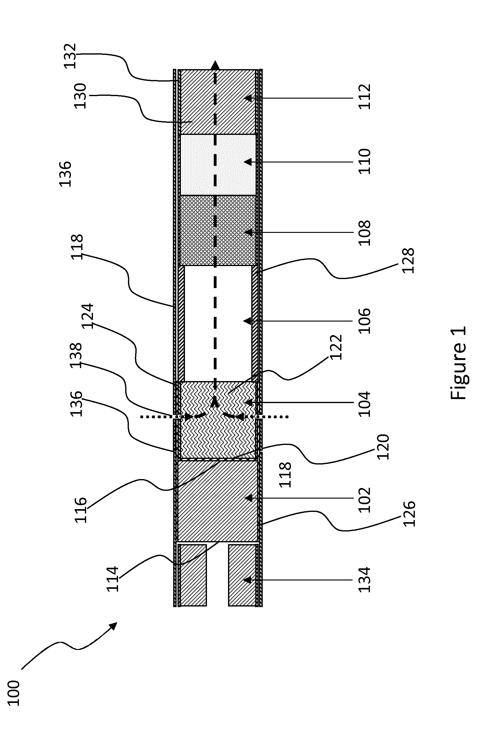
[0096] The smoking article 100 according to the first embodiment of the invention shown in FIG. 1 comprises a combustible heat source 102, an aerosol-forming substrate 104, a transfer element 106, an aerosol-cooling element 108, a spacer element 110 and a mouthpiece 112 in abutting coaxial alignment. The combustible carbonaceous heat source 102 has a front end face 114 and an opposed rear end face 116. As shown in FIG. 1, the combustible heat source 102, aerosol-forming substrate 104, transfer element 106, aerosol-cooling element 108, spacer element 110 and mouthpiece 112 are wrapped in an outer wrapper 118 of sheet material such as, for example, cigarette paper.
[0097] The combustible heat source 102 is a blind carbonaceous combustible heat source and is located at the distal end of the smoking article 100. As shown in FIG. 1, a non-combustible substantially air impermeable barrier 120 in the form of a disc of aluminium foil is provided between the rear end face 116 of the combustible carbonaceous heat source 102 and the aerosol-forming substrate 104. The barrier 120 is applied to the rear end face 116 of the combustible heat source 102 by pressing the disc of aluminium foil onto the rear end face 116 of the combustible heat source 102. The barrier 120 and abuts the rear end face 116 of the combustible carbonaceous heat source 102 and the aerosol-forming substrate 104.
[0098] The aerosol-forming substrate 104 is located immediately downstream of the barrier 120 applied to the rear end face 116 of the combustible carbonaceous heat source 102. As shown in FIG. 1, the combustible heat source 102 and the aerosol-forming substrate 104 are in abutting coaxial alignment. The aerosol-forming substrate 104 comprises a cylindrical plug of homogenised tobacco-based material 122 including an aerosol former such as, for example, glycerine, wrapped in plug wrap 124.
[0099] The transfer element 106 is located immediately downstream of the aerosol-forming substrate 104 and comprises a cylindrical open-ended hollow cellulose acetate tube 128.
[0100] The aerosol-cooling element 108 is located immediately downstream of the transfer element 106 and comprises a gathered sheet of biodegradable polymeric material such as, for example, polylactic acid.
[0101] The spacer element 110 is located immediately downstream of the aerosol-cooling element 108 and comprises a cylindrical open-ended hollow paper or cardboard tube.
[0102] The mouthpiece 112 is located immediately downstream of the spacer element 110. As shown in FIG. 1, the mouthpiece 112 is located at the proximal end of the smoking article 100 and comprises a cylindrical plug of suitable filtration material 130 such as, for example, cellulose acetate tow of very low filtration efficiency, wrapped in filter plug wrap 132. The smoking article 100 may further comprise a band of tipping paper (not shown) circumscribing a downstream end portion of the outer wrapper 118.
[0103] As shown in FIG. 1, the smoking article 100 further comprises a wrapper 126 circumscribing at least a rear portion of the combustible heat source 102 and at least a front portion of the aerosol forming substrate 104. The wrapper 126 is wrapped tightly around the combustible heat source 102 and the aerosol forming substrate 104 to maintain the correct position of the combustible heat source 102 relative to the aerosol forming substrate. In this example, the wrapper 126 is formed from a heat conductive material such as, for example, aluminium foil, such that it forms a heat conducting element. Thus, the wrapper 126 forms a thermal bridge between the combustible heat source 102 and the aerosol forming substrate to ensure sufficient conductive heat transfer from the combustible heat source 102 to the aerosol forming substrate 104. The wrapper 126 is substantially impermeable to air. Consequently, the wrapper 126 forms a barrier prior to rupture, for example to restrict the amount of moisture absorbed from the atmosphere by the combustible heat source 102 during transportation and storage. As moisture may hinder the heating performance of the heat source, restricting the amount of moisture absorbed by the heat source may have a positive impact on the performance of the smoking article 100. In other examples, the wrapper 126 may be formed from a heat insulative sheet material such as, for example, cigarette paper, of low air permeability, which is wrapped around the combustible heat source 102 and the aerosol-forming substrate 104.
[0104] In this example, the wrapper 126 overlies the entire length of the combustible heat source 102, with the exception of a front portion adjacent to the front end face 114 of the combustible heat source 102, and the entire length of the aerosol-forming substrate 104. In other embodiments of the invention (not shown), the aerosol-forming substrate 104 may extend beyond the heat-conducting element 126 in the downstream direction. That is the wrapper 126 may overlie only a front portion of the aerosol-forming substrate 104. It will be appreciated that in other embodiments of the invention (not shown), one or more additional heat-conducting elements may be provided that overlie the wrapper 126.
[0105] In this example, the smoking article 100 further comprises a removable cap 134 at its distal end and directly adjacent to the heat source 102. For example, the removable cap may comprise a central portion including a desiccant, such as glycerine, to absorb moisture as compared to the heat source, which is wrapped in a portion of the outer wrapper 118 and connected to the rest of the outer wrapper 118 along a line of weakness 136 comprising a plurality of perforations in the outer wrapper that circumscribe the smoking article. To use the smoking article, the user removes the removable cap 134 by transversely compressing the cap by pinching it between thumb and finger. By compressing the cap, sufficient force is provided to the line of weakness 136 to locally break the outer wrapper 118. The user then removes the cap by twisting the cap to break the remaining portion of the line of weakness. When the cap is removed, the front portion of the combustible heat source 102 is exposed which enables the user to light the smoking article 100.
[0106] The smoking article 100 comprises one or more air inlets 138 around the periphery of the aerosol-forming substrate 104. As shown in FIG. 1, a circumferential arrangement of air inlets 138 is provided in the plug wrap 126 of the aerosol-forming substrate 104 and the overlying outer wrapper 120 to admit cool air (shown by dotted arrows in FIG. 1) into the aerosol-forming substrate 104.
[0107] In use, the user removes the cap 134 and ignites the combustible heat source 102, which heats the aerosol-forming substrate 104 to produce an aerosol. When the user inhales on the mouthpiece 110, air (shown by dotted arrows in FIG. 1) is drawn into the aerosol-forming substrate 104 through the air inlets 138.
[0108] The front portion of the aerosol-forming substrate 104 is heated by conduction through the rear end face 116 of the combustible carbonaceous heat source 102, through the barrier 120 and through the wrapper 126 which acts as a heat conducting element.
[0109] The heating of the aerosol-forming substrate 104 by conduction releases glycerine and other volatile and semi-volatile compounds from the plug of homogenised tobacco-based material 122. The compounds released from the aerosol-forming substrate 104 form an aerosol that is entrained in the air drawn into the aerosol-forming substrate 104 of the smoking article 100 through the air inlets 138 as it flows through the aerosol-forming substrate 104. The drawn air and entrained aerosol (shown by dashed arrows in FIG. 1) pass downstream through the interior of the cylindrical open-ended hollow cellulose acetate tube 128 of the transfer element 106, the aerosol-cooling element 108 and the spacer element 110, where they cool and condense. The cooled drawn air and entrained aerosol pass downstream through the mouthpiece 112 and are delivered to the user through the proximal end of the smoking article 100. The non-combustible substantially air impermeable barrier 120 on the rear end face 116 of the combustible heat source 102 isolates the combustible heat source 102 from air drawn through the smoking article 100 such that, in use, air drawn through the smoking article 100 does not come into direct contact with the combustible heat source 102.
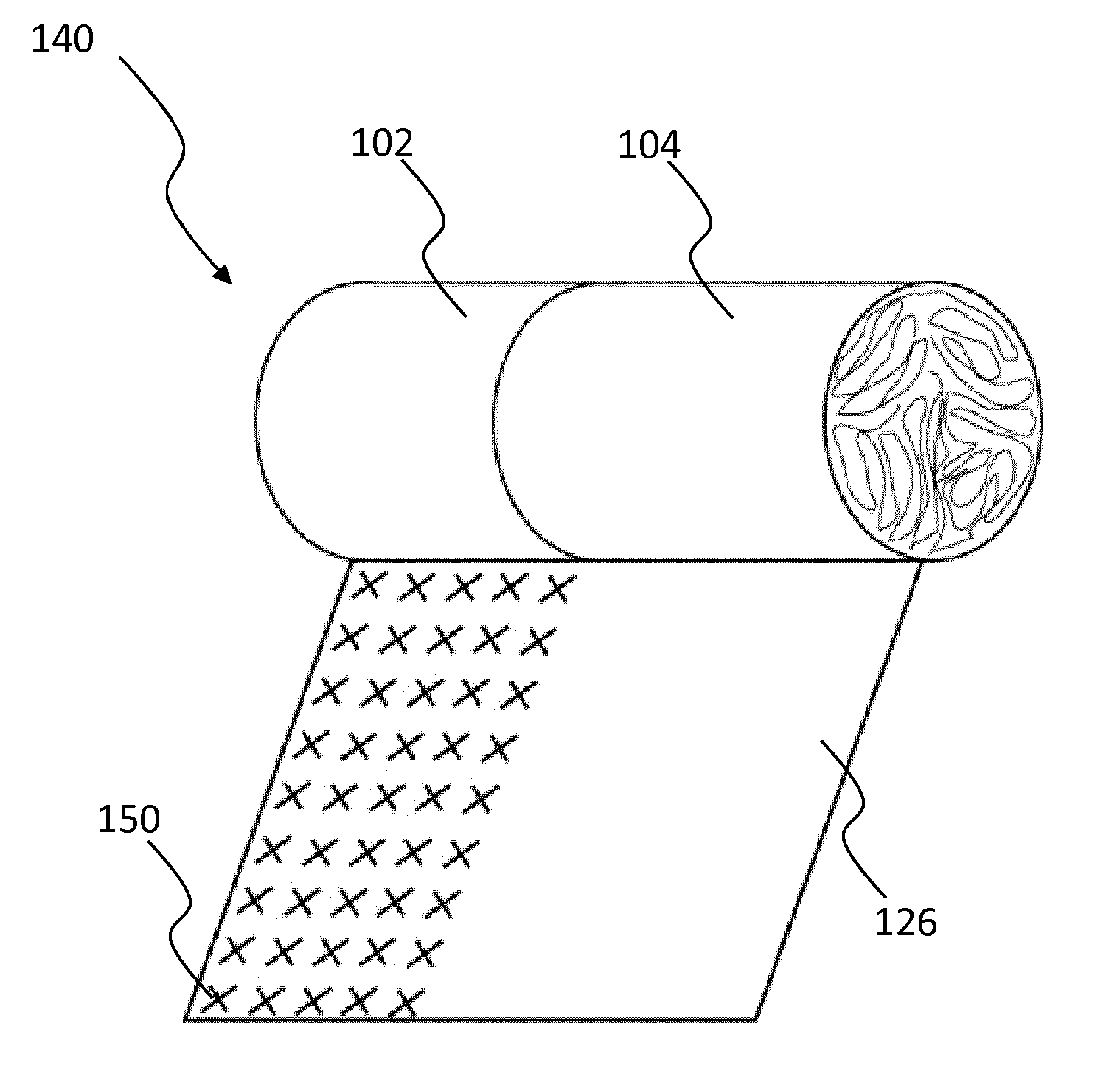
[0110] FIGS. 2A and 2B show a schematic side perspective view of a multi-segment component 140 of the smoking article 100 of FIG. 1. The multi-segment component 140 comprises the combustible heat source 102, aerosol forming substrate 104 and wrapper 126 of the smoking article 100 of FIG. 1. FIG. 2A shows the wrapper 126 circumscribing the combustible heat source 102 and the aerosol forming substrate 104. FIG. 2B shows the wrapper 126 as partially unravelled to allow the combustible heat source 102 and the aerosol-forming substrate 104 to be viewed.
[0111] The multi-segment component 140 may be pre-assembled separately to the remaining components of the smoking article for subsequent assembly, or may be manufactured and assembled together with one or more other components of the smoking article 100.
[0112] As shown in FIGS. 2A and 2B, a plurality of weakness formations 150 according to a first example are provided on a weakness region 160 of the wrapper 126 overlying the combustible heat source 102. The wrapper 126 is rupturable at the weakness formations 150 to form a ventilation zone corresponding to the weakness region 160. The weakness formations 150 are arranged in a regular pattern of aligned rows and columns on the wrapper 126 and do not extend through the thickness of the wrapper.
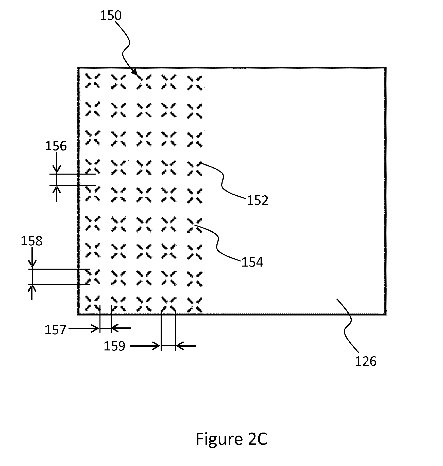
[0113] FIG. 2C shows an enlarged view of the wrapper 126 of the multi-segment component 140. In this example, the weakness formations 150 are each defined by a plurality of lines of weakness 152 extending from a central unweakened region 154. The lines of weakness 152 are oblique to the longitudinal direction of the multi-segment component 140. In this example, each weakness formation 150 is shown as including lines of weakness 152, the four lines being grouped into two pairs of collinear lines that are transverse to each other such that each weakness formation 150 is approximately `X` shaped. As the lines are of similar length, the weakness formations 150 will form approximately square shaped apertures upon rupture.
[0114] Although each weakness formation 150 is shown as being defined by four lines of weakness 152, it will be appreciated that one or more of the weakness formations may be formed from fewer or more than four lines of weakness. For example, one or more of the weakness formations may be formed from three or more lines of weakness extending from a central unweakened region. In other examples, one or more of the weakness formations may comprise two or more intersecting lines of weakness. In such examples, the lines of weakness may intersect towards either end of one or more of the lines of weakness. The intersecting lines of weakness may intersect at a central region of the weakness formation. In yet further examples, one or more weakness formations may be formed by one or more lines of weakness extending along the perimeter, or part of the perimeter, of the desired aperture shape.
[0115] Although the lines of weakness 152 are shown as being of similar length, in other examples, one or more of the lines of weakness may be of different length.
[0116] Adjacent weakness formations are separated in the circumferential direction by a circumferential separation 156 and in the longitudinal direction by a longitudinal separation 157. Preferably, the circumferential separation 156 is at least about 0.5 mm, preferably from about 0.5 mm to about 2.5 mm, more preferably from about 0.7 mm to about 1.5 mm. Preferably, the longitudinal separation 157 is at least about 0.4 mm, preferably from about 0.4 mm to about 1.8 mm, more preferably from about 0.5 mm to about 1.3 mm.
[0117] Each weakness formation has a circumferential dimension 158 and a length 159. Preferably, the circumferential dimension 158 is at least about 0.5 mm, preferably from about 0.5 mm to about 2.6 mm, more preferably from about 0.8 mm to about 1.8 mm. Preferably, the length 159 is at least about 0.1 mm, preferably from about 0.1 mm to about 2.1 mm, more preferably from about 0.2 mm to about 1.8 mm.
[0118] The weakness formations 150 are arranged so that the resulting plurality of apertures has a total aperture area which is sufficient to allow sufficient supply of air to the combustible heat source 102 and to allow sufficient venting of combustion gases from the combustible heat source 102. Preferably, the weakness formations 150 are arranged so that the resulting plurality of apertures has a total aperture area of at least about 0.09 millimetres squared, preferably from about 0.09 millimetres squared to about 40 millimetres squared, more preferably from about 0.4 millimetres squared to about 30 millimetres squared.
[0119] During use of the smoking article 100, pressure exerted on the wrapper 126 by combustion gases released by the combustible heat source 102 causes the wrapper 126 to rupture at the weakness formations 150 to form a ventilation zone comprising a plurality of apertures extending through the wrapper 126, as discussed below in relation to FIG. 3.
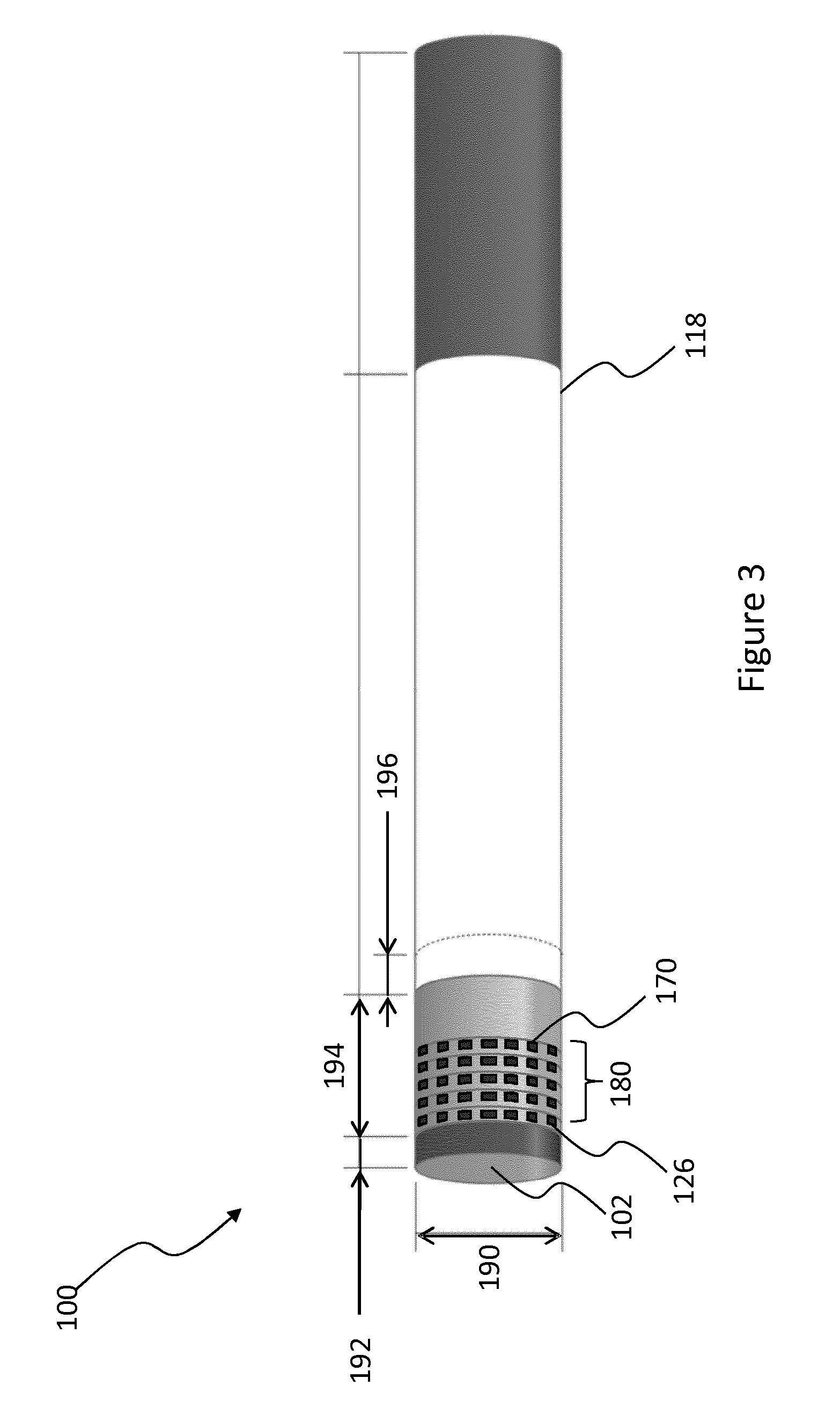
[0120] FIG. 3 shows a schematic side view of the smoking article 100 during use. As shown, the cap has been removed from the upstream end of the smoking article to allow the combustible heat source 102 to be lit by the user at its upstream end. When lit, the combustible heat source 102 generates heat and combustion gases which exert pressure on the wrapper 126. This causes the wrapper 126 to rupture at the weakness formations to form a ventilation zone 180 comprising a plurality of apertures 170 extending through the wrapper 126, with each aperture 170 corresponding to a weakness formation in the wrapper.
[0121] Due to the presence of the ventilation zone 180, the supply of air to the combustible heat source may be sufficient despite tight wrapping of the wrapper 126 around the combustible heat source 102. This ensures that there is no significant adverse effect on the amount of heat generated by the combustible heat source 102 during use, despite the extent to which the combustible heat source 102 is covered by the wrapper 126. The ventilation zone 180 also allows combustion gases generated by the combustible heat source 102 to escape through the plurality of apertures 170. This prevents a build up of excessive pressure behind the wrapper 126 which may, given the amount of the combustible heat source 102 which is covered by the wrapper 126, lead to a radial gap being formed between the wrapper 126 and the combustible heat source 102, which could in turn lead to relative movement between the combustible heat source 102 and the aerosol forming substrate 104. The ventilation zone 180 thus ensures that the heat generation by the combustible heat source 102, the conductive heat transfer from the heat source 102 to the aerosol forming substrate 104, and consequently the performance of the smoking article, is maintained, despite the extent to which the combustible heat source 102 is covered by the wrapper 126.
[0122] As shown in FIG. 3, the combustible heat source 102 has a diameter 190 and extends upstream of the upstream end of the wrapper 126 by an amount 192. The wrapper 126 extends upstream of the outer wrapper 118 by an amount 194 and is overlapped at its downstream by the outer wrapper 118 by an amount 196. Example ranges for dimensions 190, 192, 194 and 196 are shown below in Table 1.
TABLE-US-00001 EXAMPLE PREFERRED DIMENSION DIMENSION RANGE DIMENSION RANGE 190 5-12 mm 7-8.1 mm 192 0-4 mm 1-2 mm 194 4-11 mm 5-8 mm 196 1-5 mm 2-4 mm
[0123] FIG. 4A shows an enlarged view of an alternative wrapper 426 for the smoking article 100 of FIG. 1, the wrapper 426 having a plurality of weakness formations according to a second example. As shown in FIG. 4A, each weakness formation 450 comprises a circumferential line of weakness 452 and a longitudinal line of weakness 453 intersecting at a central region 454. The weakness formations 450 are arranged in a regular pattern of evenly spaced rows, with adjacent rows being longitudinally offset and alternate rows being longitudinally aligned. It will be appreciated that other patterns of weakness formation are also envisaged.
[0124] Adjacent weakness formations 450 in longitudinally aligned alternate rows are separated in the circumferential direction by a circumferential separation 456. Adjacent weakness formations 450 in each row are separated in the longitudinal direction by a longitudinal separation 457. Preferably, the circumferential separation 456 is at least about 0.5 mm, preferably from about 0.5 mm to about 2.5 mm, more preferably from about 0.7 mm to about 1.5 mm. Preferably, the longitudinal separation 457 is at least about 0.4 mm, preferably from about 0.4 mm to about 1.8 mm, more preferably from about 0.5 mm to about 1.3 mm
[0125] Each weakness formation 450 has a circumferential dimension 458 and a length 459. As the weakness formations 450 are each formed by a circumferential line of weakness 452 and a longitudinal line of weakness 453, the circumferential dimension 458 corresponds to the circumferential length of the circumferential line of weakness 452 and the longitudinal dimension 459 corresponds to the length of the longitudinal line of weakness 453. Preferably, the circumferential dimension 458 is at least about 0.5 mm, preferably from about 0.5 mm to about 2.6 mm, more preferably from about 0.8 mm to about 1.8 mm. Preferably, the length 459 is at least about 0.1 mm, preferably from about 0.1 mm to about 2.1 mm, more preferably from about 0.2 mm to about 1.8 mm.
[0126] FIG. 4B shows an enlarged view of the wrapper 426 of FIG. 4A in which the wrapper 426 has ruptured at the plurality of weakness formations to form a ventilation zone 480 comprising a plurality of apertures 470 through the wrapper 426. As shown, due to the arrangement of the weakness formations, the plurality of apertures 470 are approximately diamond shaped and the ruptured portions 472 of wrapper have remained attached to the wrapper 426. This avoids the creation of debris from the wrapper 426.
[0127] The specific embodiments and examples described above illustrate but do not limit the invention. It is to be understood that other embodiments of the invention may be made and the specific embodiments and examples described herein are not exhaustive.
* * * * *
D00000
D00001
D00002
D00003
D00004
D00005
XML
uspto.report is an independent third-party trademark research tool that is not affiliated, endorsed, or sponsored by the United States Patent and Trademark Office (USPTO) or any other governmental organization. The information provided by uspto.report is based on publicly available data at the time of writing and is intended for informational purposes only.
While we strive to provide accurate and up-to-date information, we do not guarantee the accuracy, completeness, reliability, or suitability of the information displayed on this site. The use of this site is at your own risk. Any reliance you place on such information is therefore strictly at your own risk.
All official trademark data, including owner information, should be verified by visiting the official USPTO website at www.uspto.gov. This site is not intended to replace professional legal advice and should not be used as a substitute for consulting with a legal professional who is knowledgeable about trademark law.