Reliable Telemetry
Anand; Madhukar ; et al.
U.S. patent application number 15/947198 was filed with the patent office on 2019-01-10 for reliable telemetry. This patent application is currently assigned to Infinera Corporation. The applicant listed for this patent is Infinera Corporation. Invention is credited to Madhukar Anand, Ramesh Subrahmaniam, Radhakrishna Valiveti.
| Application Number | 20190014395 15/947198 |
| Document ID | / |
| Family ID | 64902985 |
| Filed Date | 2019-01-10 |

| United States Patent Application | 20190014395 |
| Kind Code | A1 |
| Anand; Madhukar ; et al. | January 10, 2019 |
RELIABLE TELEMETRY
Abstract
A system and methods for reliable telemetry are disclosed herein. In an example of reliable in-band telemetry in a communications network, intent information for a destination device may be generated at a network device indicating a type of telemetry data to be collected. The network device may update a locally stored invertible Bloom function (IBF) by applying one or more hash function to the intent information, a destination identifier (ID) associated with the destination device, and/or a local timestamp, and periodically forward the locally stored IBF to the destination device. The network device may receive a notification message by the destination device that the intent information is missing at the destination device and re-forward the intent information to the destination device. In another example, a network device may maintain and periodically forward a locally stored IBF based on response data and the destination ID.
| Inventors: | Anand; Madhukar; (Fremont, CA) ; Subrahmaniam; Ramesh; (Fremont, CA) ; Valiveti; Radhakrishna; (Union City, CA) | ||||||||||
| Applicant: |
|
||||||||||
|---|---|---|---|---|---|---|---|---|---|---|---|
| Assignee: | Infinera Corporation Sunnyvale CA |
||||||||||
| Family ID: | 64902985 | ||||||||||
| Appl. No.: | 15/947198 | ||||||||||
| Filed: | April 6, 2018 |
Related U.S. Patent Documents
| Application Number | Filing Date | Patent Number | ||
|---|---|---|---|---|
| 62528964 | Jul 5, 2017 | |||
| Current U.S. Class: | 1/1 |
| Current CPC Class: | H04L 45/38 20130101; H04J 3/0673 20130101; G06F 16/9014 20190101; H04J 14/0267 20130101; H04L 9/3297 20130101; H04L 69/22 20130101; H04Q 11/0067 20130101; H04L 12/465 20130101; H04L 45/245 20130101; G06F 16/2322 20190101; H04L 12/4633 20130101; H04Q 9/02 20130101; H04Q 11/0066 20130101; H04Q 2011/0083 20130101; G06F 16/2477 20190101; H04Q 11/0005 20130101; H04L 9/085 20130101; H04L 2012/4629 20130101; H04L 9/3242 20130101; H04Q 11/00 20130101; H04L 12/4641 20130101; H04M 11/002 20130101 |
| International Class: | H04Q 9/02 20060101 H04Q009/02; G06F 17/30 20060101 G06F017/30; H04L 9/32 20060101 H04L009/32; H04Q 11/00 20060101 H04Q011/00 |
Claims
1. A network device comprising: a processor coupled to at least one interface; the processor and the at least one interface configured to: generate intent information for a destination device, wherein the intent information indicates a type of telemetry data to be collected along a network path to the destination device; update a locally stored invertible Bloom function (IBF) by applying at least one hash function to at least the intent information and a destination identifier (ID) associated with the destination device; and periodically forward the locally stored IBF to the destination device.
2. The network device of a claim 1, wherein the processor and the at least one interface are further configured to: forward the intent information to the destination device, wherein the locally stored IBF is forwarded with the intent information.
3. The network device of claim 1, wherein the processor and the at least one interface are further configured to: receive a notification message that the intent information is missing at the destination device based at least in part on the locally stored IBF; and re-forward the intent information to the destination device.
4. The network device of claim 1, wherein the processor and the at least one interface are further configured to: apply the at least one hash function to a local timestamp in addition to the intent information and the destination ID to update the locally stored IBF.
5. The network device of claim 1, wherein the processor and the at least one interface are further configured to: periodically receive a destination IBF calculated at the destination device; and compute a set different between the locally stored IBF and the destination IBF to determine if the intent information is missing at the destination device.
6. The network device of claim 1, wherein the processor and the at least one interface are further configured to: apply a digital signature to the intent information.
7. The network device of claim 1, wherein the processor and the at least one interface are further configured to: apply a keyed hash function to at least a secret symmetric key and a packet or frame to generate a keyed hash function value; and forward the keyed hash function value with the locally stored IBF in the packet or frame to the destination device.
8. The network device of claim 1, wherein the processor and the at least one interface are further configured to: generate second intent information for a second destination device, wherein the second intent information indicates a type of telemetry data to be collected along a second network path to the second destination device; update a second locally stored IBF by applying at least a second hash function to at least the second intent information and a destination identifier (ID) associated with the second destination device; and periodically forward the second locally stored IBF to the second destination device.
9. A network device comprising: a processor coupled to at least one interface; the processor and the at least one interface configured to: receive a packet or frame including intent information, wherein the intent information indicates a type of telemetry data to be collected along a network path to a destination device; read and translate the intent information to generate a device-specific action; execute the device-specific action to generate a local response corresponding to the intent information; encode the local response; update a locally stored invertible Bloom function (IBF) by applying at least one hash function to at least the local response and a destination identifier (ID) associated with the destination device; and periodically forward the locally stored IBF to the destination device.
10. The network device of a claim 9, wherein the processor and the at least one interface are further configured to: forward the encoded local response to the destination device, wherein the locally stored IBF is forwarded with the encoded local response.
11. The network device of a claim 9, wherein the packet or frame further includes a plurality of responses generated by other devices along the network path, and wherein the processor and the at least one interface are further configured to: apply the least one hash function to the plurality of responses in addition to the local response and the destination ID to update the locally stored IBF; and append the local response to the plurality of responses carried un the packet or frame.
12. The network device of claim 9, wherein the processor and the at least one interface are further configured to: receive a notification message that the response is missing at the destination device based at least in part on the locally stored IBF; and re-forward the local response to the destination device.
13. The network device of claim 9, wherein the processor and the at least one interface are further configured to: receive a secret symmetric key; apply a keyed hash function to at least the secret symmetric key and the packet or frame to generate a keyed hash function value; and forward the keyed hash function value with the locally stored IBF to the destination device.
14. The network device of claim 9, wherein the processor and the at least one interface are further configured to: periodically receive a destination IBF calculated at the destination device; and compute a set different between the locally stored IBF and the destination IBF to determine if the local response is missing at the destination device.
15. The network device of claim 9, wherein the processor and the at least one interface are further configured to: receive a second packet or frame including second intent information, wherein the second intent information indicates a type of telemetry data to be collected along a second network path to a second destination device; read and translate the second intent information to generate a second device-specific action; execute the second device-specific action to generate a second local response corresponding to the second intent; encode the second local response; update a second locally stored IBF by applying at least a second hash function to at least the second local response and a destination ID associated with the second destination device; and periodically forward the second locally stored IBF to the second destination device.
16. A method performed by a network device, the method comprising: generating intent information for a destination device, wherein the intent information indicates a type of telemetry data to be collected along a network path to the destination device; updating a locally stored invertible Bloom function (IBF) by applying at least one hash function to at least the intent information and a destination identifier (ID) associated with the destination device; and periodically forwarding the locally stored IBF to the destination device.
17. The method of a claim 16, further comprising: forwarding the intent information to the destination device, wherein the locally stored IBF is forwarded with the intent information.
18. The method of a claim 16, further comprising:: receiving a notification message that the intent information is missing at the destination device based at least in part on the locally stored IBF; and re-forwarding the intent information to the destination device.
19. The method of a claim 16, further comprising: applying the at least one hash function to a local timestamp in addition to the intent information and the destination ID to update the locally stored IBF.
20. The method of a claim 16, further comprising: periodically receiving a destination IBF calculated at the destination device; and computing a set different between the locally stored IBF and the destination IBF to determine if the intent information is missing at the destination device.
Description
CROSS REFERENCE TO RELATED APPLICATIONS
[0001] This application claims the benefit of U.S. Provisional Application No. 62/528,964, filed Jul. 5, 2017, which is incorporated by reference as if fully set forth herein.
FIELD OF INVENTION
[0002] The disclosure relates generally to a system and method for reliable telemetry.
BACKGROUND
[0003] Network telemetry involves the use of automated tools and processes designed to collect measurements and other data at points throughout the network, which can then be used for network monitoring and performance analysis.
[0004] In an example telemetry solution, the in-band network telemetry (INT) framework for packet networks is implemented in the data plane such that telemetry information is carried in data packets (e.g., in the header of data packets) and can be modified with each hop. The data plane refers to the part of a device's architecture that makes routing decisions for incoming packets. For example, routing may be determined by the device using a locally stored table in which the device looks up the destination address of the incoming packet and retrieves the information needed for forwarding.
[0005] The INT framework relies on programmable data planes to bring flexibility to telemetry data collection. Devices with programmable data planes include network processors or general-purpose central processing units (CPUs) at the low end, and data path programmable switch chips at the high end. With INT, a source switch (or more generally, a source network device) incorporates an instruction header to collect network state information as a part of the data packet. Intermediate INT-capable switches (devices) interpret the instruction header and collect and insert the desired network state information or responses in the data packet, which eventually reaches a sink switch and can be used as needed to monitor and evaluate the operation of the network. Advantages of INT include real-time telemetry rates, low CPU and operating system (O/S) overhead, and the flexibility to programmatically instrument packets to carry useful telemetry data.
[0006] In another example telemetry solution, the packet-optical in-band telemetry (POINT) framework provides in-band telemetry data for end-to-end correlation of collected network state data in mixed networks with multiple network layers, such as packet-optical networks. According to the POINT framework, a source device inserts an intent (POINT intent) instruction for telemetry data collection into the data flow. The intent communicates the parameters of data collection such as conditions for data collection, entities being monitored, and/or the type of data to be collected for that flow. Intermediate devices on that data flow process the high-level intent if it is targeted towards them, translate the intent into a suitable device-specific action for data collection and execute that action to collect a response.
[0007] The degree to which telemetry data can be depended on to be accurate, in other words the reliability of the data, is an important aspect of telemetry applications. For example, for the POINT framework, it is desirable to maintain reliable intent information and response information. While hop-by-hop reliability of intent/response information may use data path reliability mechanisms focused on data loss occurring along a network link (e.g., forward error correction (FEC), checksums, sequence numbers (SNs)), the end-to-end reliability of intent information may not be covered by data path reliability mechanisms. For example, intents and responses may be lost due to queuing employed at different levels (e.g., ingress/egress, layer boundary) in the devices that may not be covered by the mechanisms for detecting loss on a link. In fact, existing reliability solutions for telemetry applications may rely on best effort communications for the intent transfer across layers, and the response communication across layers. Thus, solutions for providing hop-by-hop reliability, end-to-end reliability, data integrity (i.e., the maintenance and assurance of the accuracy and consistency of data), and reliability of response aggregation are desirable for telemetry applications, including the INT and POINT frameworks.
SUMMARY
[0008] A system and methods for reliable telemetry are disclosed herein. In an example of reliable in-band telemetry in a communications network, intent information for a destination device may be generated at a network device (e.g., source device), such that the intent information indicates a type of telemetry data to be collected along a network path to the destination device. The network device may update a locally stored invertible Bloom function (IBF) by applying one or more hash function to the intent information, a destination identifier (ID) associated with the destination device, and/or a local timestamp. The network device may periodically forward the locally stored IBF to the destination device. The network device may receive a notification message generated by the destination device that the intent information is missing at the destination device based at least in part on the locally stored IBF, and re-forward the intent information to the destination device. In another example, a locally stored IBF based on response data and the destination ID may be maintained at a network device and periodically forwarded to the destination device. In an example, the disclosed reliable telemetry system and methods may be used in a packet-optical in-band telemetry (POINT) framework designed for gathering multi-layer telemetry data, which may be used in packet-optical networks.
BRIEF DESCRIPTION OF THE DRAWINGS
[0009] FIG. 1 is a high-level diagram of an example packet-optical in-band telemetry (POINT) framework implemented in an example packet-optical network, in accordance with the disclosures herein;
[0010] FIG. 2 is a high-level illustration of the set difference problem for two hosts (e.g., two network devices);
[0011] FIG. 3 is an overview of the procedure for creating an IBF data structure;
[0012] FIG. 4 is an overview of the procedure for calculating the IBF difference;
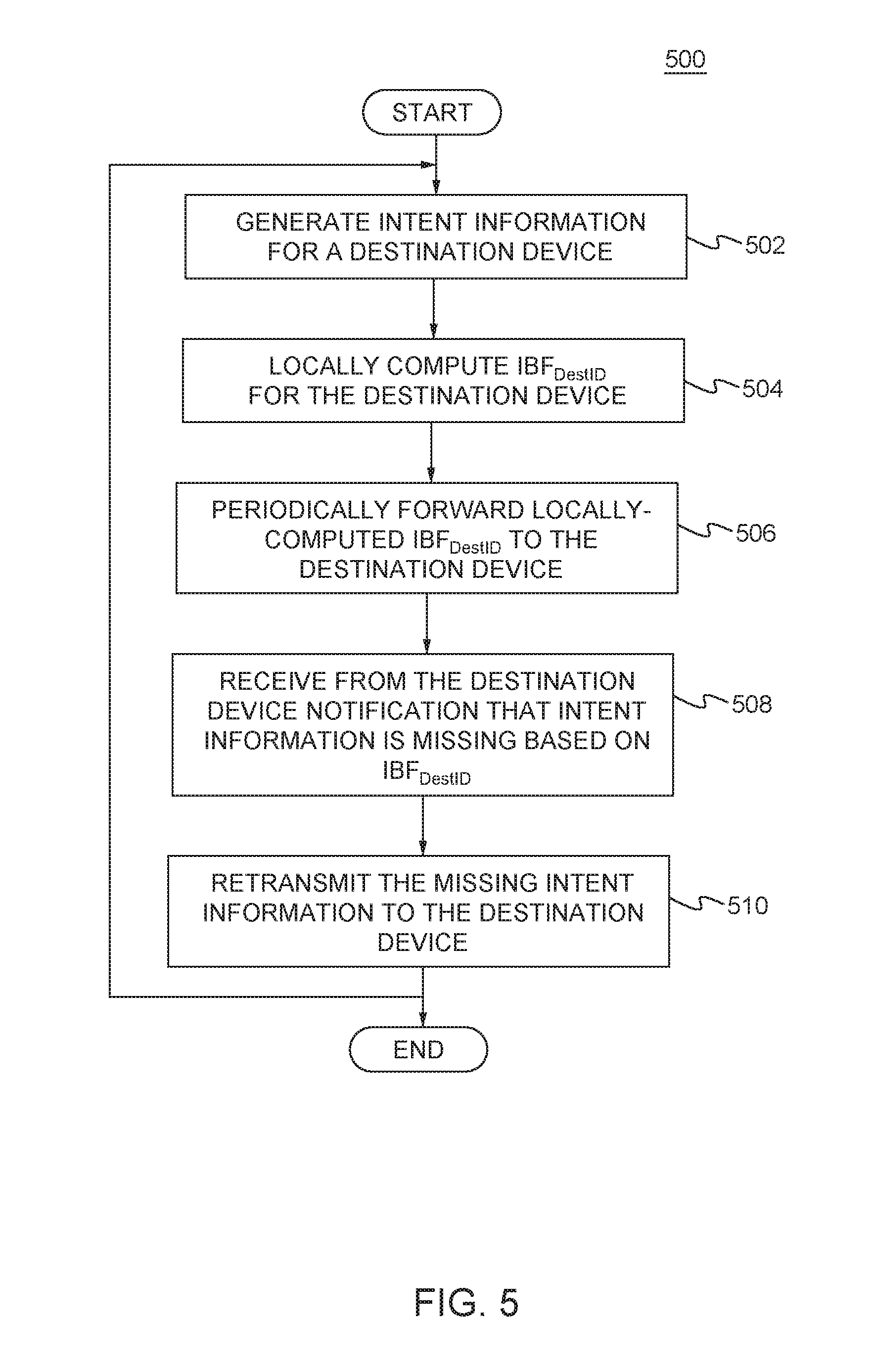
[0013] FIG. 5 is a flow diagram of an example procedure for reliable routing of intent performed by a network device that originates the intent in a POINT framework implemented in a communications network, in accordance with the disclosures herein;
[0014] FIG. 6 is a flow diagram of an example procedure for reliable routing of response data performed by a network device that generates response data in a POINT framework implemented in a communications network, in accordance with the disclosures herein; and
[0015] FIG. 7 is a block diagram of a computing system in which one or more disclosed embodiments may be implemented.
DETAILED DESCRIPTION OF THE EMBODIMENTS
[0016] In the following, telemetry applications are described in more detail and examples are given of the disclosed reliability system and method as used in telemetry applications.
[0017] Streaming telemetry mechanisms, such as OpenConfig, are designed to streamline the notification of a network state by having the network elements stream the telemetry data up to a central management entity where the data gets stored and processed. While streaming telemetry mechanisms employ extensive offline algorithms to process telemetry data, they are not designed to inherently improve the quality of the data collected. As explained above, the INT framework relies on programmable data planes to bring flexibility to telemetry data collection. The programmable data planes used in INT have been explicitly designed for packet networks; however, extending INT mechanisms into optical networks, where there is no notion of data packets, is far from straightforward due to factors such as layering and the presence of purely analog devices.
[0018] The emergence of integrated packet and optical networks, or "packet-optical networks", such as those interconnecting data centers, see additional challenges when it comes to network telemetry because of the different types of telemetry data collected in packet versus optical networks. For example, the telemetry data collected in a packet layer of a packet network, such as packet loss and latency, on a per-flow basis cannot be easily attributed to or correlated with data collected in the optical layer of an optical network, such as a bit error rate (BER) and quality factor (Q-factor). Moreover, an optical network lacks the digital constructs used by telemetry solutions such as INT, and the packet layer does not have access to measurements in the optical network. A further challenge occurs in associating packet flow telemetry data with the corresponding data from optical transport network (OTN) layers, which involves piecing together telemetry data from many devices.
[0019] Optical parameters may affect traffic flows. For example, if a link experiences degradation in Q-factor without link failure, operators can use knowledge of the degradation to proactively move critical applications away from the affected link. Thus, it is useful for network operators to be able to monitor optical parameters over time and use optical telemetry information in routing decisions and other applications.
[0020] Thus, the packet-optical in-band telemetry (POINT) framework was developed (as described in U.S. patent application Ser. No. 15/801,526, which is incorporated herein by reference in its entirety) to achieve end-to-end correlation of collected network state data in mixed networks with multiple network layers, such as packet-optical networks.
[0021] According to the POINT framework, a source device inserts intent information (i.e., POINT intent) for telemetry data collection along with the data flow. The intent communicates the parameters of data collection, such as conditions for data collection, entities being monitored, and the type of data to be collected for that flow. Intermediate devices on that data flow process the high-level intent if it is targeted towards them, translate the intent into a suitable device-specific action for data collection and execute that action to collect an intent response. At a layer boundary, such as a packet to optical boundary, or across optical layers such as a hierarchy of optical data units (ODUs), intermediate devices translate the intent and response using a layer-appropriate mechanism. For example, in the packet network, the intent and response may be encapsulated using IP options or VXLAN metadata header. At the packet-optical boundary, the intent can be retrieved from the packet header, and translated and encapsulated as ODU layer metadata, which remain accessible to all nodes along the end-to-end path of the ODU.
[0022] In another example, the POINT intent can be translated into an appropriate query for telemetry data collection via the management plane of the optical devices. As soon as the response of data collection is ready, it is communicated through the optical network and translated appropriately into a packet or packet header at the packet-optical boundary and forwarded to the sink for analysis. For example, the response communication may be out-of-band using the optical supervisory channel (OSC). The POINT framework also supports adding response metadata for incorporating deployment-specific reliability mechanisms.
[0023] Thus, the POINT framework provides hierarchical layering with intent and response translation at each layer boundary, and mapping of the intent to layer-specific data collection mechanism, such that the POINT framework can be deployed across a network layer hierarchy. The POINT framework also provides for fate sharing of telemetry intent and data flow. Telemetry data for a specific data flow can be collected in-band as the data traverses the network layers. By design, intent responses can be out-of-band to accommodate scenarios such as troubleshooting networks when there is no connectivity between the source and the sink. Additionally, intents, which are high level instructions for data collection, can be mapped to existing data collection mechanisms between two POINT capable intermediate network devices.
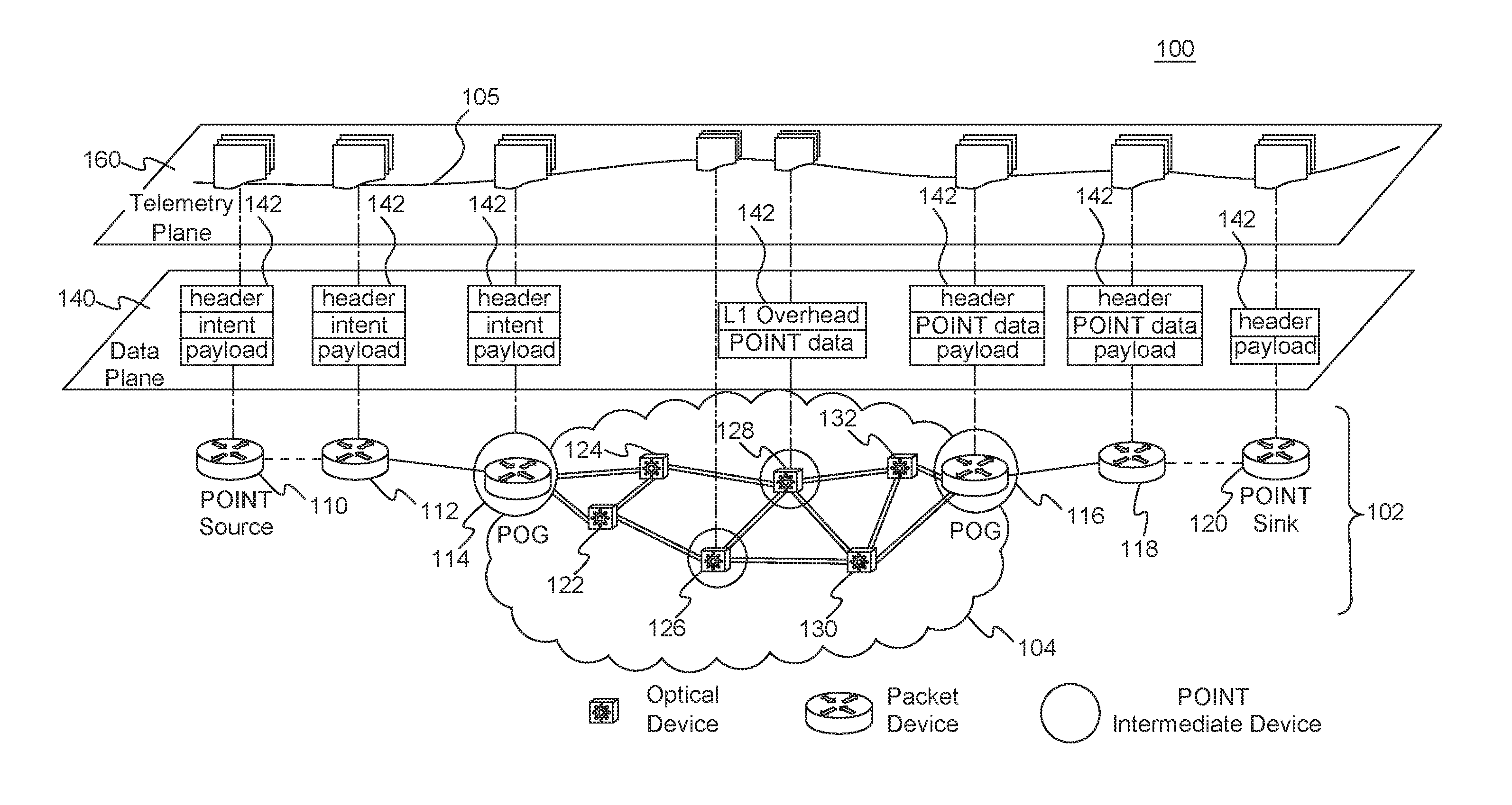
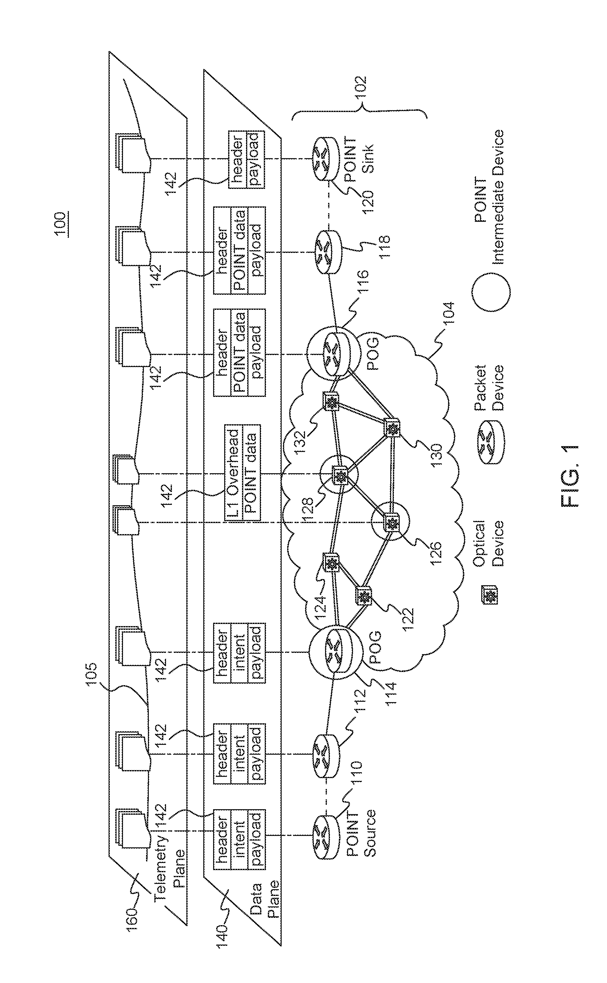
[0024] FIG. 1 is a high-level diagram of an example POINT framework 100 implemented in an example packet-optical network 102, in accordance with the disclosures herein. The example packet-optical network 102 includes packet devices 110, 112, 114, 116, 118 and 120, and an optical network 104 segment that includes optical devices 122, 124, 126, 128, 130 and 132. The POINT framework 100 can operate over an optical network 104 with Layer-0 (L0) and/or Layer-1 (L1) circuits. The packet devices include a POINT source device 110 and a POINT sink device 120, as well as packet optical gateways (POGs) 114 and 116 located at the interfaces between the packet segments and optical network 104 segment of the packet-optical network 102. The packet devices 110, 120, 114 and 116 can operate at the packet layer, for example at layer 2 (L2)/layer 3 (L3) (e.g., L2 may be a data link layer and L3 may be a network layer, which exist above a physical layer). POGs 114 and 116 are also connected via lower layer devices, such as L1/L0 devices 122, 124, 126, 128, 130 and 132. In the example packet-optical network 102, POGs 114 and 116 and optical devices 126 and 128 are configured as POINT intermediate devices (i.e., devices with digital capability to interpret POINT intent, translate it across layers, and aggregate and propagate the telemetry state information in the packet-optical network 102).
[0025] According to the POINT framework 100, telemetry information for a packet-optical traffic flow 105, such as intent or POINT data (e.g., intent and response), in the packet-optical network 102 is gathered in the data plane 140 as part of the information carried in the network 102, as described below. The telemetry plane 160 represents the telemetry information for the packet optical flow 105 being mapped and correlated across network layers, constructs (e.g., secure network communications (SNC), label-switched path (LSP), or virtual local area network (ULAN)) and devices operating at different layers in the networking stack to give the end user (e.g., at the POINT sink) a unified view of the operation of the entire packet-optical network 102.
[0026] In accordance with the disclosed POINT framework 100, a POINT source device 110 may initiate a network telemetry data collection for a packet-optical flow 105 along a packet-optical data path from the source device 110 to a sink device 120. Along the packet-optical data path, POINT intermediate devices, such as POGs 114, 116, and optical devices 126, 128, may interpret the intent, collect the desired telemetry data, and encode it back into the packet (flow) 142, which eventually gets forwarded to the sink device 120. For example, as packet (frame) 142 traverses the packet-optical network 102 across devices and layers (e.g., packet layers L2/L3 and optical layers L1/L0) in the data plane 140, intent information is transferred into other layers and translated into device-specific actions, and responses are collected (e.g., added to POINT data in packet 142) for use at the POINT sink device 120. At the sink device 120, the collected telemetry data for the packet-optical flow 105 (collected from POINT source device 110 to POINT sink device 120) is processed as needed by the intended applications. Examples of telemetry data processing may include triggering a report to a management entity (e.g., using mechanisms like OpenConfig) or archiving collected data in a storage device.
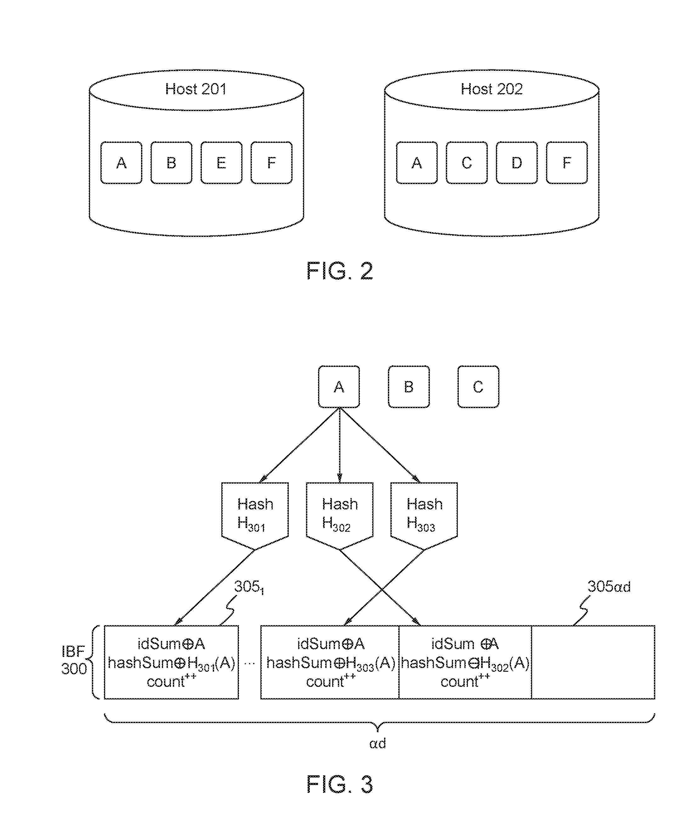
[0027] According to the disclosures herein, a sufficient degree of reliability of applications for networking and distributed systems, including telemetry, may be achieved by using solutions to the set difference problem for distributed applications that need to compare remote states. FIG. 2 is a high-level illustration of the set difference problem for two hosts (e.g., network devices). The set difference problem seeks to determine which data or objects are unique to host 201 (in this example, data B and E) and which data or objects are unique to host 202 (in this example, data C and D). By enhancing a telemetry application with a solution to the set difference problem, reliability may be provided because missing data from the source device may be identified by the destination device, or vice versa (i.e., data synchronization). Additionally, solutions to the set difference problem may identify duplicate data.
[0028] According to the disclosures herein, a possible solution to the set difference problem is the difference digest that allows two nodes (e.g., hosts, devices) to compute the elements belonging to the set difference in a single round with communication overhead proportional to the size of the difference times the logarithm of the keyspace. The difference digest may use invertible Bloom filters (IBFs), as described in the following. An IBF is a data structure that efficiently computes the set difference between two sets and uses the size of the difference. According to the difference digest, local object identifiers (IDs) (i.e., numbers that uniquely identify each object or element, where the object may be telemetry data such as intent or response data) at a host (e.g., objects A, B, E, F local to host 201, and objects A, C, D, F local to host 202 in FIG. 2) may be encoded into an IBF at the respective host.
[0029] An overview of an example algorithm for generating an IBF is described in the following. An empty IBF, prior to application of the hash functions, may consist of an array of in bits set to `0`, where in is proportional to the number of data elements (e.g., Object IDs for telemetry data) to be encoded. To populate the IBF, k hash functions may be used to map (or hash) each set element (e.g., an Object ID) to one of the in array positions to generate a uniform random distribution. A hash function is a function that maps data of an arbitrary size (e.g., multiple object IDs) to data of a fixed size (e.g., the hash value, hash code, or hash). Examples of types of hash functions that may be used for creating the IBF data structure may include, but are not limited to, MurmurHash functions or Fowler-Noll-Vo (FNV) hash functions.
[0030] In an example, the number of hash functions, k, may be a constant and may be less than the number of bits in the IBF, in. To add an element (e.g., Object ID) to the IBF, each of the k hash functions may be applied to the element to generate k array positions, and the bits associated with the k array positions may be set to T. To query for an element in the IBF to determine if the element is in the set, the k hash functions may be applied to the element to obtain k' array positions. If any of the bits at the k' array positions is set to `0`, then it can be determined that the queried element is not in the set. If all of the bits at the k' array positions are set to `1`, then it can be determined that the queried element is in the set or the bits have been erroneously set to `1` (e.g., due the insertion of other elements) resulting in a false positive. Although the IBF set difference algorithm is referred to herein, any other set difference algorithm may be used.
[0031] FIG. 3 is an overview of the procedure for creating an IBF data structure 300 at a host. For each object (e.g., objects with ID A, B, C, and which may represent telemetry data such as intent data or response data) stored on the host, one or more hash functions (e.g., hash functions H.sub.301, H.sub.302, H.sub.303) may be applied to the object ID to generate a hash value, represented by H(objectID) (e.g., H.sub.301(A)) and the hash sum (i.e., exclusive-OR (XOR)) may be taken of the hash function value.
[0032] The IBF data structure 300 may include an array of IBF cells 305.sub.1 . . . 305.sub.ad each containing: idSum equal to the exclusive-OR (XOR) of all object IDs in the cell; H(objectID), which is the hash value for all object IDs in the cell; hashSum equal to the XOR of one or more hash values (i.e., hash functions applied to object IDs); and count equal to the number of object IDs assigned to the cell. Each object ID (e.g., A, B, C) may be hashed multiple times using different hash functions H.sub.301, H.sub.302, H.sub.303 and assigned to different IBF cells 305.sub.1 . . . 305.sub.ad, and for a set difference of size d, ad IBF cells are used where a is an integer greater than 1. IBFs may be created in this manner at the two hosts, and the local IBF may then be traded with the remote host (e.g., host 201 trades it's local IBF with host 202 in FIG. 2) to calculate the set (IBF) difference.
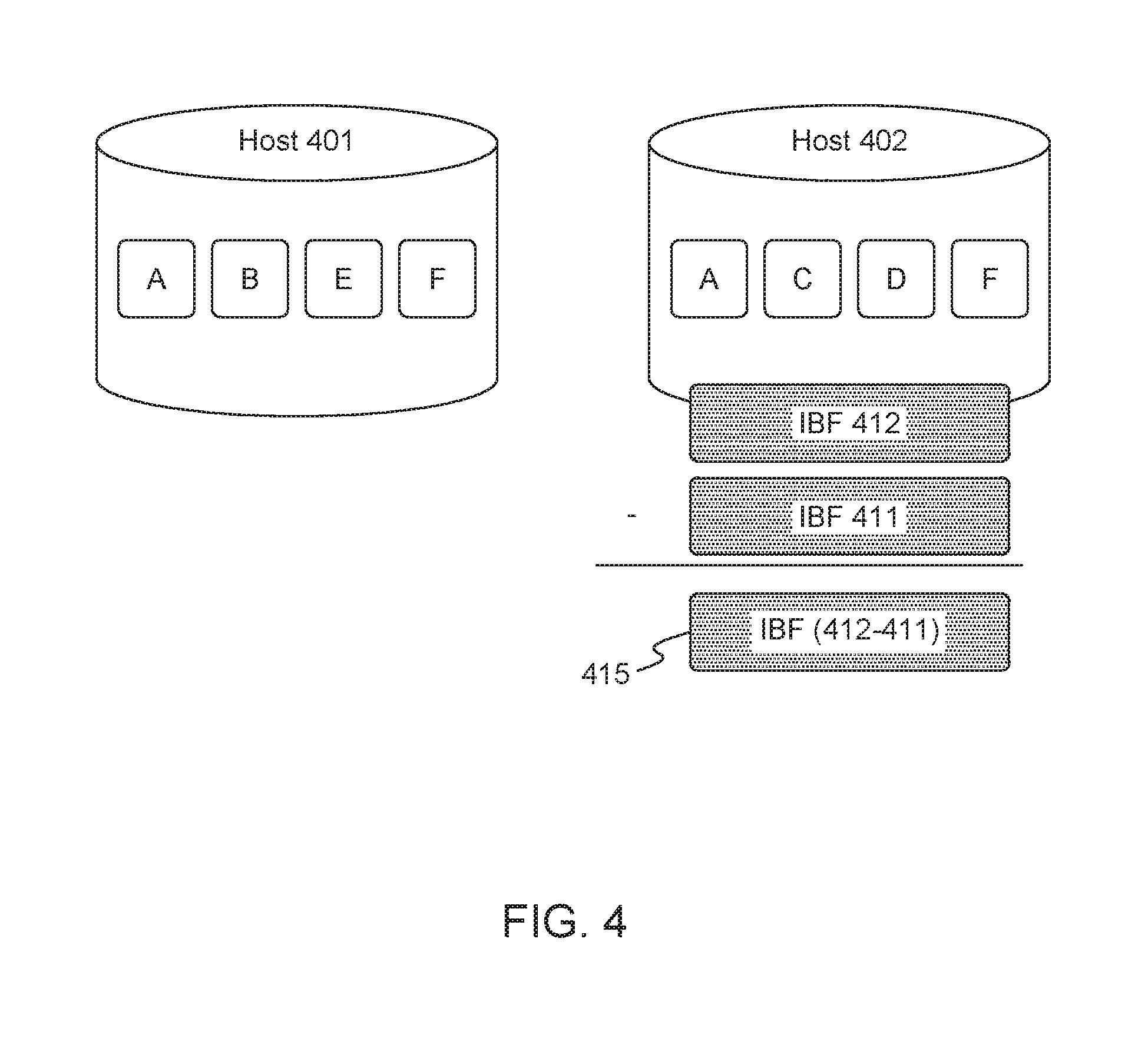
[0033] FIG. 4 is an overview of the procedure for calculating the IBF difference. In this example, host 401 has provided its local IBF 411 to host 402, and host 402 takes the set difference (e.g., using the approach described above) between IBF structures 412 and 411 to produce a new IBF 415 containing only unique object IDs for the objects that are on host 401 and not on host 402.
[0034] According to the disclosures herein, IBFs, or any other set difference algorithm, may be used to provide reliability of intent and/or response data for in-band telemetry applications such as the INT or POINT frameworks. Examples of the disclosed reliability methods and systems are given in the following with reference to the POINT framework; however, any of the disclosed reliability mechanisms, alone or in combination, may be used in any telemetry application, including, but not limited to INT, POINT, and OpenConfig.
[0035] According to an example reliable telemetry solution for the intent in a POINT framework, intent information is included in the data path and forwarded along with the data at each networking element (e.g., packet device, optical device, etc.). If local action is warranted at a network element based on the intent, the networking element may copy the intent and execute an appropriate data collection action. At the point of intent origination (e.g. the POINT source device), which may be, for example, a layer boundary such as at the packet-optical layer boundary, once the intent is forwarded, a local destination IBF that is associated with the destination device of the intent (e.g., POINT sink device or node) is updated. The destination device may maintain a corresponding IBF. A different IBF may be maintained by the source device for each device that is a destination for locally-originating intent. Note that the source device and sink device may be intermediate devices, such as layer boundary devices, along a network path.
[0036] End-to-end reliability for the intent is achieved by the exchange of the IBFs periodically between source device and sink device of a network path, or between devices at layer boundaries along a network path. The source and sink devices (or layer boundary devices) that exchange respective IBFs may take the set difference between the two IBFs to determine if telemetry information (e.g., intent and/or response) is missing at the sink or destination device. For example, if it is determined by the sink device (or layer boundary device) by computing the IBF set difference that particular intent information is missing at the sink device (or a layer boundary device), then the sink device may send a notification message to the source device (i.e., the originating device of the intent) to request retransmission of the missing intent.
[0037] In an example, IBF computed for the intent at a POINT device (e.g., source device, sink device) may involve the POINT device computing a hash function (e.g., Murmur hash or FNV hash) over the following data (or a subset of the following data): the intent, the destination ID, and/or the source timestamp. The intent and the destination ID are used to distinguish from IBFs for other intent and destinations, and the source timestamp may be included to distinguish telemetry data requests over time. In an example, data freshness can be used to check if intent is fresh instead of the timestamp. In some cases, telemetry data requests (i.e., intent) may be repeated over time. Devices need to distinguish between two requests for the same data that are separated over a time frame (e.g., current temperature queried every hour) and repeated queries for the data within that time frame (e.g., current temperature queried multiple times within the same hour). According to an example, the request data (i.e., intent) may be timestamped and the timestamp may then be used to distinguish between the two scenarios. In another example, response data may be flagged as stale or expired based on freshness criteria or a freshness time threshold, such that response data for the intent may be discarded if the response data does not meet the freshness criteria or threshold (e.g., temperature readings collected more than one hour prior to receiving the intent information are discarded). In another example, every network element along the data path may compute a local destination IBF using the destination ID.
[0038] In an example, data integrity may be ensured by including digital signatures of querying entities along with the intent. For example, the source device may apply a digital signature to the intent information. This may be done using the elliptic curve digital signature algorithm or Rivest-Shamir-Adleman (RSA) algorithm. In another example, a device at a layer boundary (e.g., a POG), along with intent translation, may include the digital signature of the source device with the intent. In another example, an intermediate device along the network path may verify a digital signature included with the intent to authenticate the source and intent before generating a response to the intent.
[0039] FIG. 5 is a flow diagram of an example procedure 500 for reliable routing of intent performed by a network device that originates the intent in a POINT framework implemented in a communications network, in accordance with the disclosures herein. For example, the network device may be a packet device or an optical device. The network device may be source device or a layer boundary device (e.g., a POG). At 502, the network device may generate intent information for a particular destination device (e.g., sink device or layer boundary device). At 504, the network device may generate and maintain an IBF, IBF.sub.DestID, for the intent information destined for the destination device. The IBF may be computed by applying at least one hash function to the intent information and/or the destination ID of the destination device (and/or the source timestamp). Each time new intent information is generated, the network device may update the IBF.sub.DestID associated with the destination device.
[0040] At 506, the network device may periodically forward the locally computed IBF.sub.DestID to the destination device. For example, the network device may forward IBF.sub.DestID in-band using the same channel as response communication or using an out-band channel such as management channel. The frequency with which the network device forwards IBF.sub.DestID may be at set time intervals (e.g., at every one minute interval), or each time new intent information is generated, for example. In an example, the destination device may compute the set different between the received and locally generated IBF.sub.DestID's. In the case that intent is determined to be missing at the destination device, at 508, the network device may receive a notification message from the destination device indicating which intent information is missing.
[0041] In an example not shown in FIG. 5, the network device and the destination device may exchange their locally computed IBF.sub.DestID's. In other words, in addition to the network device periodically forwarding its locally computed IBF.sub.DestID to the destination device, the network device may also periodically receive, from the destination, the IBF.sub.DestID.sub._.sub.2 calculated at the destination device. In this case, the network device may compute the set difference between IBF.sub.DestID and IBF.sub.DestID.sub._.sub.2 to determine if any intent information is missing at the destination device.
[0042] With reference to FIG. 5, if intent information is determined to be missing (either by notification from the destination device or by local computation of the IBF set difference), then, at 510, the network device may retransmit the missing intent information to the destination device. In an example, intent caching at intermediate devices along the network path between the source device and destination device may be used to quickly retransmit the missing intent at the cost of intent storage at the intermediate device. The procedure 500 may be performed each time intent information is generated at the network device.
[0043] The procedure 500 may be performed by the network device for multiple destination devices in parallel, such that unique destination IBFs may be maintained for each respective destination device. Additionally, the procedure 500 may be performed by an intermediate device along the network path other than the source device that originated the intent information.
[0044] The network device may read the POINT intent from the data (packet or frame). If intent instructions apply to the network device, the network device may translate the intent into a suitable device-specific action for data collection, execute that action, and the response. The network device may forward the intent on the outbound interface along the network path. The network device may update the destination IBF associated with the destination IBF.sub.DestID.
[0045] As explained above, the destination device may also calculate a local IBF. The destination device may generate and maintain a local IBF, IBF.sub.DestID.sub._.sub.2, for the intent information associated with its own destination ID and/or the source ID (to distinguish from IBFs from other source devices). The IBF.sub.DestID.sub._.sub.2 may be computed by applying at least one hash function to the intent information and/or the destination ID at the destination device (and/or the source timestamp). Each time new intent information is received, the destination device may update the IBF.sub.DestID.sub._.sub.2. The destination device may periodically receive from the source device (i.e., the device that originated the intent) the IBF.sub.DestID that was computed at the source device. For example, the destination device may receive IBF.sub.DestID in-band over the same channel as response communication or over an out-band channel such as management channel. The destination device may compute the set different between the received and locally generated IBF.sub.DestID's. In the case that intent is determined to be missing at the destination device, the destination device may send a notification message to the source device indicating which intent information is missing.
[0046] In the following, example reliable telemetry solutions for the response data in a POINT framework (or any in-band telemetry framework, such as INT) are described, in accordance with the disclosures herein. In the POINT framework, response data generated (i.e., in response to received intent) by a device along the network path may be forwarded hop-by-hop by intermediate devices along the network path to the destination (sink) device. In an example, response data may be stored and forwarded at each network device along the network path using the data forwarding mechanisms programmed/configured on those network devices. In an example, an intermediate network device may append its respective local response(s) to the data packet/frame carrying existing responses as the data packet/frame is forwarded along the network path. In another example, in some cases, the locally generated response data at a network device may be aggregated with the existing response data that is being carried in the data frame/packet.
[0047] In order to achieve hop-by-hop and end-to-end reliability for response data, in the case that local responses are appended to a data frame/packet as it traverses the network, a response IBF.sub.response associated with the destination may be generated and updated along with the response data at each device along the network path. For example, the response data and IBF.sub.response carried in the data frame/packet may have the following structure: {<Device ID.sub.1, Response.sub.1>, . . . <Device ID.sub.n, Response.sub.n>, IBF.sub.response}, where the Response.sub.i was generated by the device with Device ID.sub.i, and IBF.sub.response is based on the accumulated responses Response.sub.1 . . . Response.sub.n in the data frame/packet. In an example, any device that generates a response along the network path may also update the IBF.sub.response by taking a hash function over <DeviceID, Response> for all device/response pairs in the data frame or packet including the locally generated response for the device itself. Then, the updated IBF.sub.response may replace the previous IBF.sub.response in the data frame/packet and thus be forwarded along the network path toward the destination device.
[0048] The destination device (e.g., sink device or layer boundary device) may locally compute/re-compute IBF.sub.response.sub._.sub.2 based on the responses it has received and compare IBF.sub.response.sub._.sub.2 with the IBF.sub.response received in the data frame/packet in order to compute the set difference of the IBFs and determine which responses are missing at the destination device. For response data determined to be missing, the destination device may send a notification message to an intermediate device and/or the source device to request retransmission of the missing response data. For example, this may result in the missing response data being retransmitted, and/or the intent information associated with the missing response data being retransmitted. In an example, for high loss rates of response data, other set difference algorithms, such as difference digests that maintain a number of IBFs along with an estimate of the size of set difference, may be used instead of IBFs.
[0049] In order to achieve data integrity of response data, in the case that local responses are appended to a data frame/packet as it traverses the network ("append model"), cryptographic hash functions with IBFs and/or digital signatures may be used. For example, as response data traverses a network path from source device to the destination device, each intermediate device may update the bloom filter (e.g., IBF.sub.response) and forward the response data and bloom filter along the network path, as described above. As described above, the sink device (or a layer boundary device), may verify the contents of the data and re-compute the bloom filter IBF.sub.response. If the filter values match up, then the response contents are deemed valid and forwarded. In an example, bloom filter calculation may use a cryptographic hash function SHA-1, such that the source device and sink device share keys with intermediate devices along the network path to use in the cryptographic hash function computation. Each device may update the bloom filter IBF.sub.response using the shared key(s) and known hash functions.
[0050] In another example, the intermediate device that is the originator of response data and the destination device may exchange a keyed hash function value (HMac(K;m)) in addition to the IBF in order to authenticate and validate the data integrity of response data and the IBF. For example, let H() denote a cryptographic hash function, and HMAC() denote a keyed hash function for message authentication. To authenticate a message m (e.g., a frame or packet) with a secret symmetric key K, the keyed has function HMac(K;m) may be calculated according to the following equation:
HMac(K;m)=H((K.sym.ipad).parallel.k H((K.sym.ipad)k.parallel.m)) Equation 1
where .parallel. denotes concatenation, .sym. denotes exclusive-OR (XOR), opad is the one-block-size outer padding (0x5c5c:::5c), and ipad is the one-block-size inner padding (0x3636:::36). In an example, the source device may calculate HMac(K;m) the data and shared keys, and include it in a packet header with the response data and IBF. The destination device may also locally HMac.sub.2(K;m). The destination device may proceed to use a received IBF when the HMAC(K;m) received from the source device matches the locally computed HMac.sub.2(K;m). If the locally computed HMac.sub.2(K;m) does not match the HMAC(K;m) received from the source device, the destination device then it may be considered that the data has been tampered with and the destination device may choose to discard the received IBF and/or response data. The approaches described above for data integrity and authentication, including the use of cryptographic hash functions, digital signatures, and keyed hash functions, may be used in a similar fashion described for intent data and/or response data.
[0051] FIG. 6 is a flow diagram of an example procedure 600 for reliable routing of response data performed by a network device that generates response data in a POINT framework implemented in a communications network, in accordance with the disclosures herein. For example, the network device may be a packet device or an optical device. The network device may be any intermediate device that generates response data along the network path between the source device and the destination device. At 602, the network device may receive and read intent information in a received data packet or frame. At 604, the network device may process (e.g., translate) the intent and generate a response.
[0052] At 606, the network device may generate and maintain an IBF, IBF.sub.DestID, for the response information destined for the destination device. The IBF IBF.sub.DestID may be computed by applying at least one hash function to the locally-generated response information and/or the destination ID of the destination device (and/or the local timestamp). Each time new response information is generated, the network device may update the IBF.sub.DestID associated with the destination device. The hash function may be a cryptographic hash function, as described above.
[0053] At 608, the network device may periodically forward the locally computed IBF.sub.DestID to the destination device. For example, the network device may forward IBF.sub.DestID in-band using the same channel as response communication or using an out-band channel such as a management channel. The frequency with which the network device forwards IBF.sub.DestID may be at set time intervals (e.g., every 15 minutes), or each time new intent information is generated, for example. In an example, the destination device may compute the set different between the received and locally generated IBF.sub.DestID. In the case that response data is determined to be missing at the destination device, at 610, the network device may receive a notification message from the destination device indicating which response information is missing.
[0054] In an example not shown in FIG. 6, the network device and the destination device may exchange their locally computed IBF.sub.DestID's. In other words, in addition to the network device periodically forwarding its locally computed IBF.sub.DestID to the destination device, the network device may also periodically receive, from the destination, the IBF.sub.DestID.sub._.sub.2 calculated at the destination device. In this case, the network device may compute the set difference between IBF.sub.DestID and IBF.sub.DestID.sub._.sub.2 to determine if any response information is missing at the destination device.
[0055] With reference to FIG. 6, if response information is determined to be missing (either by notification from the destination device or by local computation of the IBF set difference), then, at 612, the network device may retransmit the missing response information to the destination device. In an example, response caching at intermediate devices along the network path between the network device and destination device may be used to quickly retransmit the missing response data at the cost of intent storage at the intermediate device. The procedure 600 may be performed each time response information is generated at the network device, and the IBF.sub.DestID may be updated each time new response data is locally generated for the associated destination device. The procedure 600 may be performed by the network device for multiple destination devices in parallel, such that unique destination IBFs may be maintained for each respective destination device.
[0056] As explained above, the destination device may also calculate a local IBF. The destination device may generate and maintain a local IBF, IBF.sub.DestID.sub._.sub.2, for the response information associated with its own destination ID and/or the ID of the originating device of the response data. The IBF.sub.DestID.sub._.sub.2 may be computed by applying at least one hash function to the response information and/or the destination ID at the destination device (and/or the source timestamp). Each time new response information is received, the destination device may update the IBF.sub.DestID.sub._.sub.2. The destination device may periodically receive from the source device (i.e., the device that originated the response) the IBF.sub.DestID that was computed at the source device. For example, the destination device may receive IBF.sub.DestID in-band over the same channel as response communication or over an out-band channel such as management channel. The destination device may compute the set different between the received and locally generated IBF.sub.DestID's. In the case that response data is determined to be missing at the destination device, the destination device may send a notification message to the source device indicating which response information is missing.
[0057] In an example, the disclosed reliable telemetry methods and system, and any subset or one or more component(s) thereof, may be implemented using software and/or hardware and may be partially or fully implemented by computing devices, such as the computing device 700 shown in FIG. 7.
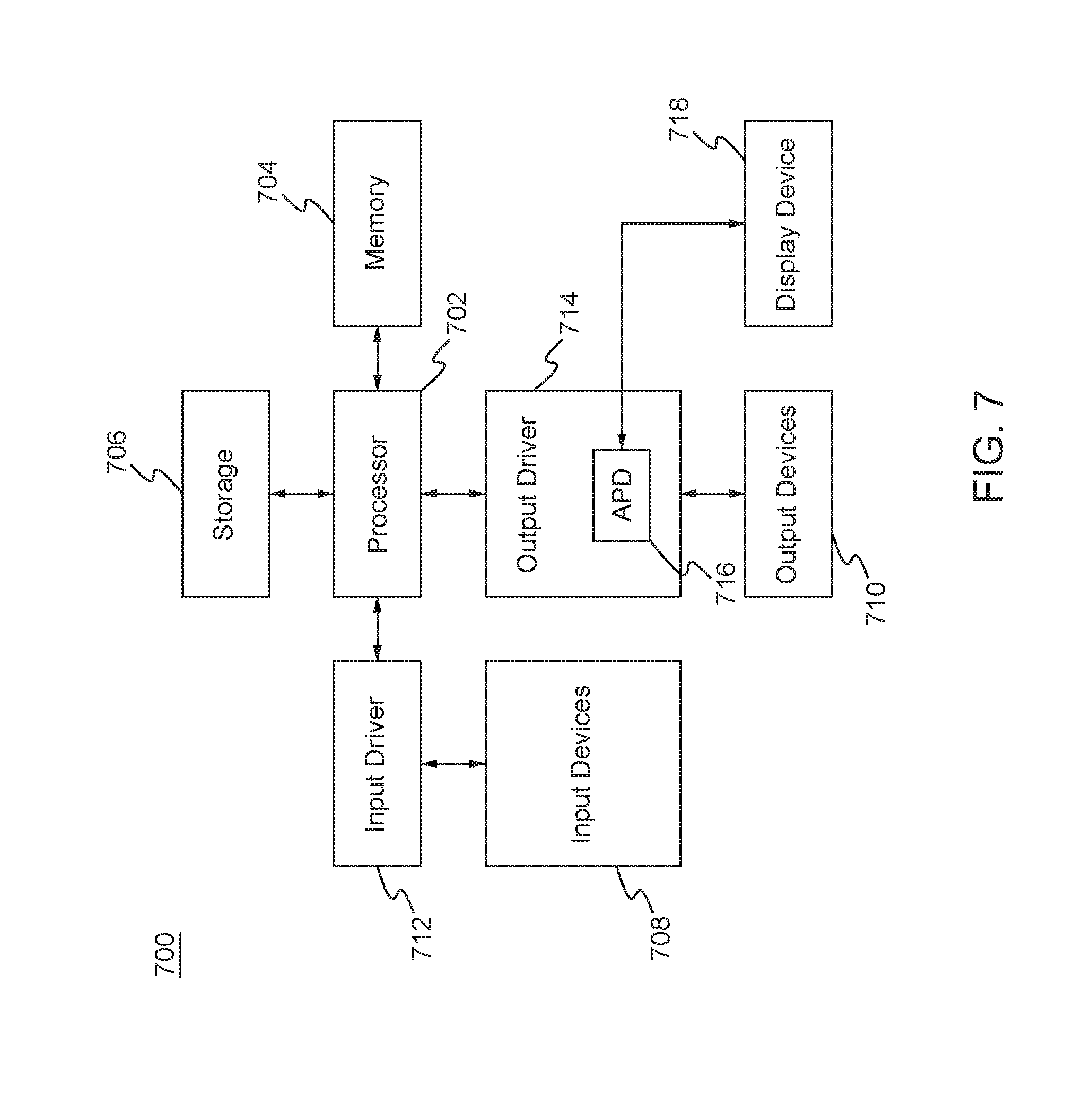
[0058] FIG. 7 is a block diagram of a computing system 700 in which one or more disclosed embodiments may be implemented. The computing system 700 may include, for example, a computer, a switch, a router, a gaming device, a handheld device, a set-top box, a television, a mobile phone, or a tablet computer. The computing device 700 may include a processor 702, a memory 704, a storage device 706, one or more input devices 708, and/or one or more output devices 710. The input devices 708 and output devices 710 may be generally referred to as interfaces for the computing device 700. The device 700 may include an input driver 712 and/or an output driver 714. The device 700 may include additional components not shown in FIG. 7.
[0059] The processor 702 may include a central processing unit (CPU), a graphics processing unit (GPU), a CPU and GPU located on the same die, or one or more processor cores, wherein each processor core may be a CPU or a GPU. The memory 704 may be located on the same die as the processor 702, or may be located separately from the processor 702. The memory 704 may include a volatile or non-volatile memory, for example, random access memory (RAM), dynamic RAM, or a cache.
[0060] The storage device 706 may include a fixed or removable storage, for example, a hard disk drive, a solid state drive, an optical disk, or a flash drive. The input devices 708 may include a keyboard, a keypad, a touch screen, a touch pad, a detector, a microphone, an accelerometer, a gyroscope, a biometric scanner, or a network connection (e.g., a wireless local area network card for transmission and/or reception of wireless IEEE 802 signals). The output devices 710 may include a display, a speaker, a printer, a haptic feedback device, one or more lights, an antenna, or a network connection (e.g., a wireless local area network card for transmission and/or reception of wireless IEEE 802 signals).
[0061] The input driver 712 may communicate with the processor 702 and the input devices 708, and may permit the processor 702 to receive input from the input devices 708. The output driver 714 may communicate with the processor 702 and the output devices 710, and may permit the processor 702 to send output to the output devices 710. The output driver 716 may include an accelerated processing device ("APD") 716 which may be coupled to a display device 718. The APD may be configured to accept compute commands and graphics rendering commands from processor 702, to process those compute and graphics rendering commands, and to provide pixel output to display device 718 for display.
[0062] In an example, with reference to FIG. 1, the point source 110, packet devices 112 ad 118, optical devices 122-132, and/or POGs 114, may be implemented, at least in part, with the components of computing device 700 shown in FIG. 7. Similarly, the procedures 500 and 600 shown in FIGS. 5 and 6 may be implemented, at least in part, with the components of computing device 700 shown in FIG. 7.
[0063] It should be understood that many variations are possible based on the disclosure herein. Although features and elements are described above in particular combinations, each feature or element may be used alone without the other features and elements or in various combinations with or without other features and elements.
[0064] The methods and elements disclosed herein may be implemented in/as a general purpose computer, a processor, a processing device, or a processor core. Suitable processing devices include, by way of example, a general purpose processor, a special purpose processor, a conventional processor, a digital signal processor (DSP), a plurality of microprocessors, one or more microprocessors in association with a DSP core, a controller, a microcontroller, Application Specific Integrated Circuits (ASICs), Field Programmable Gate Arrays (FPGAs) circuits, any other type of integrated circuit (IC), and/or a state machine. Such processors may be manufactured by configuring a manufacturing process using the results of processed hardware description language (HDL) instructions and other intermediary data including netlists (such instructions capable of being stored on a computer readable media). The results of such processing may be maskworks that are then used in a semiconductor manufacturing process to manufacture a processor which implements aspects of the embodiments.
[0065] The methods, flow charts and elements disclosed herein may be implemented in a computer program, software, or firmware incorporated in a non-transitory computer-readable storage medium for execution by a general purpose computer or a processor. Examples of non-transitory computer-readable storage mediums include a read only memory (ROM), a random access memory (RAM), a register, cache memory, semiconductor memory devices, magnetic media such as internal hard disks and removable disks, magneto-optical media, and optical media such as CD-ROM disks, and digital versatile disks (DVDs).
* * * * *
D00000
D00001
D00002
D00003
D00004
D00005
D00006
XML
uspto.report is an independent third-party trademark research tool that is not affiliated, endorsed, or sponsored by the United States Patent and Trademark Office (USPTO) or any other governmental organization. The information provided by uspto.report is based on publicly available data at the time of writing and is intended for informational purposes only.
While we strive to provide accurate and up-to-date information, we do not guarantee the accuracy, completeness, reliability, or suitability of the information displayed on this site. The use of this site is at your own risk. Any reliance you place on such information is therefore strictly at your own risk.
All official trademark data, including owner information, should be verified by visiting the official USPTO website at www.uspto.gov. This site is not intended to replace professional legal advice and should not be used as a substitute for consulting with a legal professional who is knowledgeable about trademark law.