Microled Display Panel
Wu; Biing-Seng ; et al.
U.S. patent application number 16/128287 was filed with the patent office on 2019-01-10 for microled display panel. The applicant listed for this patent is Prilit Optronics, Inc.. Invention is credited to Fa-Ming Chen, Biing-Seng Wu.
| Application Number | 20190013307 16/128287 |
| Document ID | / |
| Family ID | 64902912 |
| Filed Date | 2019-01-10 |


| United States Patent Application | 20190013307 |
| Kind Code | A1 |
| Wu; Biing-Seng ; et al. | January 10, 2019 |
MICROLED DISPLAY PANEL
Abstract
A micro light-emitting diode (microLED) display panel includes microLEDs; a substrate for supporting the microLEDs, the substrate being divided into a plurality of sub-regions; and a plurality of chip-on-film (COF) packages mounted on surfaces of the sub-regions respectively, a plurality of drivers being disposed on the COF packages respectively.
| Inventors: | Wu; Biing-Seng; (Tainan City, TW) ; Chen; Fa-Ming; (Tainan City, TW) | ||||||||||
| Applicant: |
|
||||||||||
|---|---|---|---|---|---|---|---|---|---|---|---|
| Family ID: | 64902912 | ||||||||||
| Appl. No.: | 16/128287 | ||||||||||
| Filed: | September 11, 2018 |
Related U.S. Patent Documents
| Application Number | Filing Date | Patent Number | ||
|---|---|---|---|---|
| 15703458 | Sep 13, 2017 | |||
| 16128287 | ||||
| Current U.S. Class: | 1/1 |
| Current CPC Class: | H01L 33/58 20130101; H01L 23/5387 20130101; H01L 25/0753 20130101; H01L 33/486 20130101; G09G 2310/0267 20130101; G09G 2310/08 20130101; G09G 2310/0275 20130101; H01L 25/167 20130101; G09G 3/32 20130101; G09G 2300/06 20130101 |
| International Class: | H01L 25/16 20060101 H01L025/16; H01L 25/075 20060101 H01L025/075; H01L 23/538 20060101 H01L023/538 |
Foreign Application Data
| Date | Code | Application Number |
|---|---|---|
| Sep 26, 2016 | TW | 105131054 |
| Jun 7, 2017 | TW | 106118892 |
Claims
1. A micro light-emitting diode (microLED) display panel, comprising: a plurality of microLEDs; a substrate for supporting the microLEDs, the substrate being divided into a plurality of sub-regions; and a plurality of chip-on-film (COF) packages mounted on surfaces of the sub-regions respectively, a plurality of drivers being disposed on the COF packages respectively.
2. The microLED display panel of claim 1, wherein the COF package comprises a flexible printed circuit board (FPCB), which includes at least a main region and a bonding region, the driver being disposed on the main region.
3. The microLED display panel of claim 2, wherein the bonding region is substantially smaller in size than the main region, and the bonding region is adjacent to one edge of the main region.
4. The microLED display panel of claim 2, wherein the driver has connection pins disposed on four edges of the driver, and the connection pins are then electrically routed to finger connectors disposed on the bonding region.
5. The microLED display panel of claim 2, wherein the bonding region is bent along a boundary between the bonding region and the main region, and the bonding region is then mounted on the substrate.
6. The microLED display panel of claim 2, wherein the FPCB stands on the substrate at an angle between 0 and 180 degrees.
7. The microLED display panel of claim 1, wherein the microLED display panel is a backside illuminating microLED display panel that generates light emitting downward from a bottom surface of the substrate.
8. The microLED display panel of claim 1, wherein the substrate comprises an insulating material.
9. The microLED display panel of claim 8, wherein the substrate comprises glass or Acrylic.
10. The microLED display panel of claim 1, wherein the COF package comprises a main region, a first bonding region and a second bonding regions, the first bonding region and the second bonding region being adjacent to opposite edges of the main region, respectively.
11. The microLED display panel of claim 10, wherein the first bonding region adopts outer lead bonding (OLB) technique, and the second bonding region adopts inner lead bonding (ILB) technique.
12. The microLED display panel of claim 1, wherein some of the drivers are mounted on boundary sub-regions of the substrate by using either chip-on-glass (COG) or COF technique, while others of the drivers are mounted on center sub-regions of the substrate by using COF technique.
Description
CROSS-REFERENCE TO RELATED APPLICATIONS
[0001] This application is a continuation-in-part application of US application Ser. No. 15/703,458, filed on Sep. 13, 2017, which claims priority to Taiwan Application No. 105131054, filed on Sep. 26, 2016, and Taiwan Application No. 106118892, filed on Jun. 7, 2017. The entire contents of all of the foregoing applications are herein expressly incorporated by reference.
BACKGROUND OF THE INVENTION
1. Field of the Invention
[0002] The present invention generally relates to a display panel, and more particularly to a microLED display panel.
2. Description of Related Art
[0003] A micro light-emitting diode (microLED, mLED or .mu.LED) display panel is one of flat display panels, which is composed of microscopic microLEDs each of a size of 1-10 micrometers. Compared to conventional liquid crystal display panels, the microLED display panels offer better contrast, response times and energy efficiency. Although both organic light-emitting diodes (OLEDs) and microLEDs possess good energy efficiency, the microLEDs, based on group III/V (e.g., GaN) LED technology, offer higher brightness, higher luminous efficacy and longer lifespan than the OLEDs.
[0004] Active matrix using thin-film transistors (TFT) may be used in companion with microLEDs to drive a display panel. However, microLED is made by flip chip technology, while TFT is made by complementary metal-oxide-semiconductor (CMOS) process which is more complex than flip chip technology. These two distinct technologies may cause thermal mismatch. A drive current of the microLED is small in gray display, which may be significantly affected by leakage current.
[0005] Passive matrix is another driving method performed by a row drive circuit and a column drive circuit, which are disposed on the periphery of a display panel. When the size or the resolution of the display panel increases, output loading and delay of the drive circuits increase accordingly, causing the display panel to malfunction. Therefore, passive matrix is not suitable for large-size microLED display panels.
[0006] A need has thus arisen to propose a novel microLED display panel, particularly a large-size or high-resolution display panel, which is capable of maintaining advantages of microLEDs and overcoming disadvantages of driving schemes.
SUMMARY OF THE INVENTION
[0007] In view of the foregoing, it is an object of the embodiment of the present invention to provide a microLED display panel capable of effectively reducing loading of drivers, thereby making whole large-size high-resolution microLED display panel feasible.
[0008] According to one embodiment, a micro light-emitting diode (microLED) display panel includes microLEDs, a substrate and chip-on-film (COF) packages. The substrate supports the microLEDs and is divided into a plurality of sub-regions. The COF packages are mounted on surfaces of the sub-regions respectively, and a plurality of drivers are disposed on the COF packages respectively.
BRIEF DESCRIPTION OF THE DRAWINGS
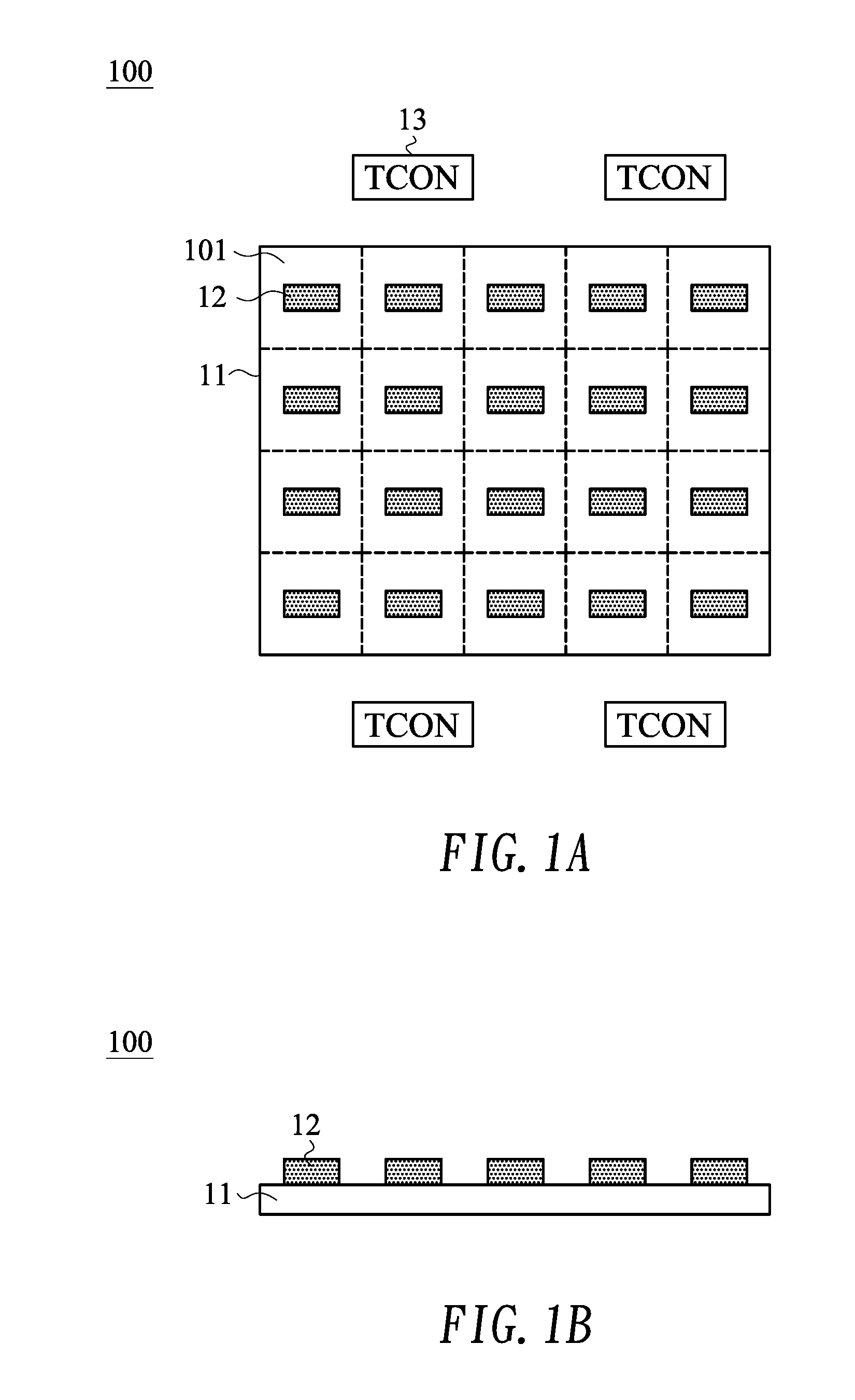
[0009] FIG. 1A shows a top view illustrated of a microLED display panel according to one embodiment of the present invention;
[0010] FIG. 1B shows a side view illustrated of the microLED display panel of FIG. 1A;
[0011] FIG. 2 shows a schematic diagram illustrated of passive driving the microLED display panel;
[0012] FIG. 3 shows a cross-sectional view illustrated of a frontside illuminating microLED display panel according to a first specific embodiment of the present invention;
[0013] FIG. 4 shows a cross-sectional view illustrated of a backside illuminating microLED display panel according to a second specific embodiment of the present invention;
[0014] FIG. 5 shows an exemplary current-voltage curve of a microLED;
[0015] FIG. 6 shows a system block diagram illustrated of a driver according to one embodiment of the present invention;
[0016] FIG. 7A shows a schematic diagram illustrating a chip-on-film (COF) package for a driver according to one embodiment of the present invention;
[0017] FIG. 7B shows a side view illustrating the COF package of FIG. 7A mounted on a substrate of a microLED display panel according to one embodiment of the present invention;
[0018] FIG. 8A to FIG. 8C schematically show a top view, a front side view and a right-hand side view, respectively, illustrating a microLED display panel with COF packages mounted thereon;
[0019] FIG. 9A to FIG. 9C schematically show a top view, a front side view and a right-hand side view, respectively, illustrating a microLED display panel with drivers mounted thereon by COG technique;
[0020] FIG. 10A shows a schematic diagram illustrating a chip-on-film (COF) package for a driver according to another embodiment of the present invention;
[0021] FIG. 10B shows a side view illustrating the COF package of FIG. 10A mounted on a substrate and a printed circuit board of a microLED display panel according to one embodiment of the present invention; and
[0022] FIG. 11 schematically shows a top view illustrating a microLED display panel.
DETAILED DESCRIPTION OF THE INVENTION
[0023] FIG. 1A shows a top view illustrated of a micro light-emitting diode (microLED) display panel 100 according to one embodiment of the present invention, and FIG. 1B shows a side view illustrated of the microLED display panel 100 of FIG. 1A. The microLED display panel of the embodiment is preferably adaptable to a large-size and high-resolution (e.g., 3840RGB.times.2160) display panel. In the specification, the size range of the microLED is between 1 and 10 micrometers. However, the size of the microLED may be even smaller due to specific applications or technological advance. In the specification, "large-size" display panel is currently and commonly referred to 10 inches or above display panel. However, "large-size" display panel may be referred to other display size due to specific applications or technological advance. In the specification, "high-resolution" display panel is currently and commonly referred to a display panel with 1080 or above scan lines. However, "high-resolution" display panel may be referred to other amount of scan lines due to specific applications or technological advance.
[0024] In the embodiment, the microLED display panel 100 may include a substrate 11 for supporting a plurality of microLEDs (not shown). The substrate 11 may be preferably made of an insulating material (e.g., glass or Acrylic) or other materials suitable for supporting the microLEDs.
[0025] According to one aspect of the embodiment, a surface of the substrate 11 is divided into a plurality of sub-regions 101. It is noted that the divided sub-regions 101 are not physically cut through, and the substrate 11 is not made by integrating the sub-regions 101. In other words, the substrate 11 or the microLED display panel 100 is a single or whole entity, or an uncut entity. FIG. 1A shows a simplified example of how the substrate 11 is divided into sub-regions 101. Take a microLED display panel 100 with resolution 3840RGB.times.2160 as an example, the substrate 11 may be divided into 80.times.54 sub-regions 101, each having resolution 48RGB.times.40. Nevertheless, this microLED display panel 100 may be divided into more or less sub-regions 101.
[0026] According to another aspect of the embodiment, the microLED display panel 100 may include a plurality of drivers 12, which are correspondingly disposed on (e.g., top) surfaces of the sub-regions 101 respectively. The driver 12 as exemplified in FIG. 1A may, but not necessarily, be disposed in the center of the surface of corresponding sub-region 101. Each sub-region 101 as exemplified in FIG. 1A has one corresponding driver 12. However, in other embodiments, each sub-region 101 may have plural corresponding drivers 12. The driver 12 of the embodiment may be manufactured as an integrated circuit or chip, which is then bonded on the surface of the sub-region 101, for example, by surface-mount technology (SMT) such as chip-on-glass (COG) or flip chip. In one example, the drivers 12 and the microLEDs are disposed on the same surface of the substrate 11.
[0027] The microLED display panel 100 of the embodiment may further include a plurality of timing controllers (TCON) 13, which are electrically connected with the substrate 11, for example, via a flexible printed circuit board (FPCB), and are further electrically connected with corresponding drivers 12, for example, via signal traces (not shown) disposed on the substrate 11. In the embodiment, one timing controller 13 may be electrically connected with at least two drivers 12. In other words, the amount of the timing controllers 13 may be less than the amount of the drivers 12. The timing controller 13 may be electrically connected directly with corresponding drivers 12 via signal traces. Alternatively, the timing controller 13 may be electrically connected to one driver 12 via signal traces, and, after signal buffering, then be electrically connected to another driver 12 via signal traces.
[0028] According to a further aspect of the embodiment, the microLED display panel 100 may adopt passive driving method for driving the microLEDs. FIG. 2 shows a schematic diagram illustrated of passive driving the microLED display panel 100. The timing controller 13 transmits timing control signals and data signals to the driver 12. The driver 12 may include a column drive circuit 121 and a row (or scan) drive circuit 122. The column drive circuit 121 transmits column drive signals to first electrodes (e.g., anodes) of the microLEDs 14 on the same columns via column conductive wires 1211, and the row drive circuit 122 transmits row drive signals to second electrodes (e.g., cathodes) of the microLEDs 14 on the same rows via row conductive wires 1221. In the embodiment, the column drive circuit 121 and the row drive circuit 122 are made in a single integrated circuit.
[0029] According to the embodiment discussed above, the substrate 11 of the microLED display panel 100 is divided into sub-regions 101, each of which has a corresponding driver 12. Therefore, loading of the column drive circuit 121 and the row drive circuit 122 may be effectively reduced, thereby making whole large-size high-resolution microLED display panel feasible. Moreover, the microLED display panel 100 of the embodiment adopts a passive driving method (instead of active driving method using thin-film transistors) for driving the microLEDs 14, thereby simplifying the process of making display panels, reducing turn-on time of the microLEDs 14, increasing drive current, and effectively minimizing effect on gray display due to leakage current.
[0030] FIG. 3 shows a cross-sectional view illustrated of a frontside illuminating microLED display panel 300 according to a first specific embodiment of the present invention. In the embodiment, the microLEDs 14 and the driver 12 are disposed above a top surface of the substrate 11. Light generated by the microLEDs 14 primarily emits upward (i.e., frontside illuminating) from the top surface of the substrate 11 as indicated by arrows.
[0031] As exemplified in FIG. 3, each pixel may include a red microLED 14R, a green microLED 14G and a blue microLED 14B. A trace layer 15 is disposed between a (e.g., top) surface of the substrate 11 and the microLEDs 14 and the driver 12. The trace layer 15 is configured to electrically connect the driver 12, the microLEDs 14 and the timing controller 13. A light blocking layer 16 is disposed between adjacent pixels and above the trace layer 15. The light blocking layer 16 of the embodiment may be made of black matrix (BM) or other materials suitable for blocking light. In one embodiment, the light blocking layer 16 may be optionally disposed among the red microLED 14R, the green microLED 14G and the blue microLED 14B of the same pixel.
[0032] A light guide layer 17 may be disposed above the red microLED 14R, the green microLED 14G and the blue microLED 14B. The frontside illuminating microLED display panel 300 of the embodiment may further include a cover plate 18 disposed on a bottom surface of the substrate 11. The cover plate 18 of the embodiment may be made of an opaque material.
[0033] FIG. 4 shows a cross-sectional view illustrated of a backside illuminating microLED display panel 400 according to a second specific embodiment of the present invention. In the embodiment, the microLEDs 14 and the driver 12 are disposed above a top surface of the substrate 11. Light generated by the microLEDs 14 primarily emits downward (i.e., backside illuminating) from the bottom surface of the substrate 11 as indicated by arrows.
[0034] As exemplified in FIG. 4, each pixel may include a red microLED 14R, a green microLED 14G and a blue microLED 14B. A light blocking layer 16 is disposed between adjacent pixels and above a (e.g., top) surface of the substrate 11. The light blocking layer 16 of the embodiment may be made of black matrix (BM) or other materials suitable for blocking light. A trace layer 15 is disposed above the light blocking layer 16 for electrically connecting the driver 12, the microLEDs 14 and the timing controller 13. In one embodiment, the light blocking layer 16 may be optionally disposed among the red microLED 14R, the green microLED 14G and the blue microLED 14B of the same pixel.
[0035] A light guide layer 17 may be disposed above the red microLED 14R, the green microLED 14G and the blue microLED 14B. The backside illuminating microLED display panel 400 of the embodiment may further include a cover plate 18 disposed above the driver 12, the trace layer 15, the light blocking layer 16 and the light guide layer 17. The cover plate 18 of the embodiment may be made of an opaque material.
[0036] FIG. 5 shows an exemplary current-voltage curve of a microLED 14. When an operating voltage is greater than a turn-on voltage Vf (e.g., 3 volts), a current greater than a predetermined value may be obtained to normally operate and turn on the micro-LED 14. For the microLED display panel 100 shown in FIG. 1A, a system power for the drivers 12 is VDDA. However, a voltage drop .DELTA.V exists in the center of the microLED display panel 100 due to impedance in the conductive wire for transferring the power. Accordingly, the drivers 12 disposed in the center of the microLED display panel 100 in fact receive power of VDDA-.DELTA.V, although the drivers 12 disposed on the periphery of the microLED display panel 100 receive power of VDDA. For example, assume the voltage drop .DELTA.V is 1 volt and the turn-on voltage Vf is 3 volts. The condition under which the drivers 12 may be normally operated is VDDA-1>3, that is, VDDA>4 (e.g., VDDA of 5 volts is required). In this situation, the drivers 12 may be made by low-voltage metal-oxide-semiconductor (MOS) process.
[0037] Nevertheless, as the amount of microLEDs 14 increases, consumed current then increases and a voltage drop .DELTA.V significantly increases accordingly (e.g., increases to 4 volts). The condition under which the drivers 12 may be normally operated is VDDA-4>3, that is, VDDA>7 (e.g., VDDA of 8 volts is required). In this situation, the drivers 12 should be made by high-voltage metal-oxide-semiconductor (MOS) process, which results in larger circuit area that is unfavorable for making large-size high-resolution (e.g., 3840RGB.times.2160) display panel. For overcoming the problems, an architecture of a novel driver 12 is proposed.
[0038] FIG. 6 shows a system block diagram illustrated of a driver 12 according to one embodiment of the present invention. In the embodiment, the driver 12 may include a low-dropout (LDO) regulator 123 and a drive circuit 120. The LDO regulator 123 receives a system power VDDA, according to which a regulated power VR (e.g., 5 volts) is generated and provided as a power for the drive circuit 120. The LDO regulator 123 of the embodiment may be implemented according to circuit design of conventional LDO regulators, and details of which are thus omitted for brevity. The drive circuit 120 of the embodiment may include a column drive circuit 121 and a row drive circuit 122. The LDO regulator 123 is one of direct-current (DC) linear regulators, which are configured to generate a regulated power VR substantially equal to the system power VDDA. Compared to a switching regulator, the LDO regulator 123 occupies less circuit area with simpler circuit design and without switching noise. In the embodiment, a smoothing capacitor C may be interposed between the regulated power VR and earth, thereby filtering out high-frequency noise. The smoothing capacitor C may be formed with a metal layer process (instead of extra process) commonly used in display panel manufacturing.
[0039] According to the driver 12 of the embodiment as discussed above, only the LDO regulator 123 should be made by high-voltage (e.g., greater than 8 volts) MOS process, while the drive circuit 120 may be made by low-voltage (e.g., less than 8 volts) MOS process. On the contrary, for a driver without LOD regulator 123, entire driver 12 should be made by high-voltage MOS process. As a result, the driver 12 of the embodiment may significant reduce circuit area and facilitate making large-size or high-resolution display panels.
[0040] FIG. 7A shows a schematic diagram illustrating a chip-on-film (or chip-on-flex) (COF) package 700 for a driver 12 (a display driver integrated circuit (DDIC) in this case) according to one embodiment of the present invention. The COF package 700 may include a flexible printed circuit board (FPCB) 71, which may include at least a main region 711 and a bonding region 712. The bonding region 712 is substantially smaller in size than the main region 711, and the bonding region 712 is adjacent to one edge of the main region 711.
[0041] The COF package 700 of the embodiment may include a driver 12 mounted on the main region 711. Specifically, a chip, such as the driver 12 in this case, has connection pins 713 disposed on four edges of the chip. The connection pins 713 of the chip are then electrically routed to finger connectors 714 of the bonding region 712 via traces (not shown) on the main region 711. Accordingly, connection pins 713 on four edges of the chip are thus transformed to the finger connectors 714 disposed on only one edge of the FPCB 71, that is, on the bonding region 712.
[0042] FIG. 7B shows a side view illustrating the COF package 700 of FIG. 7A mounted on a substrate 11 of a microLED display panel according to one embodiment of the present invention. Specifically, in the embodiment, the bonding region 712 is bent along a boundary between the bonding region 712 and the main region 711, and the bonding region 712 is then mounted on the substrate 11. Accordingly, the driver 12 is hanging in the air above the substrate 11. Although the main region 711 of the FPCB 71 stands at a 90 degree angle as exemplified in FIG. 7B, it is appreciated that, generally speaking, the FPCB 71 may stand on the substrate 11 at an angle between 0 and 180 degrees.
[0043] FIG. 8A to FIG. 8C schematically show a top view, a front side view and a right-hand side view, respectively, illustrating a microLED display panel 800 with COF packages 700 mounted thereon. In the embodiment, the microLED display panel 800 may preferably be a backside illuminating microLED display panel, as exemplified in FIG. 4, that generates light emitting downward from the bottom surface of the substrate 11.
[0044] In the embodiment, the microLED display panel 800 may include a substrate 11 for supporting a plurality of microLEDs (not shown). The substrate 11 may be preferably made of an insulating material (e.g., glass or Acrylic) or other materials suitable for supporting the microLEDs. The surface of the substrate 11 is divided into a plurality of sub-regions 101. According to one aspect of the embodiment, the microLED display panel 800 may include a plurality of COF packages 700 respectively mounted on a top surface of the sub-regions 101 the substrate 11. The microLED display panel 800 of the embodiment may include a plurality of drivers 12 mounted on the main regions 711 of the COF packages 700, respectively. As described above in connection with FIG. 7B, the COF package 700 is mounted on (or bounded with) the substrate 11 via the bonding region 712 such that the driver 12 is hanging above the substrate 11. As the bonding region 712 requires substantially less area compared to the main region 711 or the driver 12, the COF package 700 occupies only a substantially small area of the substrate 11, and majority of the precious area of the substrate 11 may thus be provided for placing, among others, microLEDs.
[0045] Compared with chip-on-glass (COG) technique adopted in other embodiments, in which (connection pins of) the chips (i.e., the drivers 12) are directly mounted on the surface of the substrate 11, the COF packages 700 of the present embodiment occupy substantially less area than the COG embodiments. FIG. 9A to FIG. 9C schematically show a top view, a front side view and a right-hand side view, respectively, illustrating a microLED display panel 900 with drivers 12 mounted thereon by COG technique. As the drivers 12 are directly mounted on the substrate 11, the drivers 12 occupy substantive area of the precious area of the substrate 11 with less area left for placing the microLEDs. In this concern, the drivers 12 need be fabricated smaller but with more technical difficulties and higher cost. Moreover, the COF package 700 can substantially overcome voltage-drop effect caused by long trace in large-size microLED display panels. Further, trace width may be shrank, thus effectively increasing resolution of the microLED display panels.
[0046] FIG. 10A shows a schematic diagram illustrating a chip-on-film (COF) package 700B for a driver 12 according to another embodiment of the present invention. The COF package 700B is similar to the COF package 700 of FIG. 7A, with the exception that, in the COF package 700B, the flexible printed circuit board (FPCB) 71 may include a main region 711, a first bonding region 712A and a second bonding region 712B. The first bonding region 712A and the second bonding region 712B are adjacent to opposite edges of the main region 711, respectively. In the embodiment, the first bonding region 712A adopts outer lead bonding (OLB) technique for bonding with a glass, and the second bonding region 712B adopts inner lead bonding (ILB) technique for bonding with a printed circuit board.
[0047] FIG. 10B shows a side view illustrating the COF package 700B of FIG. 10A mounted on a substrate 11 (e.g., glass) of a microLED display panel via the first bonding region 712A and mounted on a printed circuit board 11B (e.g., FPCB) via the second bonding region 712B according to one embodiment of the present invention. In one example, the printed circuit board 11B is electrically connected to a control system such as timing controllers (TCON).
[0048] FIG. 11 schematically shows a top view illustrating a microLED display panel 1100. In the embodiment, drivers (not shown) may be mounted on (non-shaded) boundary sub-regions 101 by using either COG or COF technique, while other drivers may be mounted on (shaded) center sub-regions 101 by using COF technique, thereby facilitating connecting the drivers mounted on the center sub-regions 101 to the timing controllers.
[0049] Although specific embodiments have been illustrated and described, it will be appreciated by those skilled in the art that various modifications may be made without departing from the scope of the present invention, which is intended to be limited solely by the appended claims.
* * * * *
D00000
D00001
D00002
D00003
D00004
D00005
D00006
D00007
D00008
D00009
D00010
XML
uspto.report is an independent third-party trademark research tool that is not affiliated, endorsed, or sponsored by the United States Patent and Trademark Office (USPTO) or any other governmental organization. The information provided by uspto.report is based on publicly available data at the time of writing and is intended for informational purposes only.
While we strive to provide accurate and up-to-date information, we do not guarantee the accuracy, completeness, reliability, or suitability of the information displayed on this site. The use of this site is at your own risk. Any reliance you place on such information is therefore strictly at your own risk.
All official trademark data, including owner information, should be verified by visiting the official USPTO website at www.uspto.gov. This site is not intended to replace professional legal advice and should not be used as a substitute for consulting with a legal professional who is knowledgeable about trademark law.