Plate Heat Exchanger
TANAKA; Nobuo
U.S. patent application number 16/065935 was filed with the patent office on 2019-01-10 for plate heat exchanger. The applicant listed for this patent is HISAKA WORKS, LTD.. Invention is credited to Nobuo TANAKA.
| Application Number | 20190011193 16/065935 |
| Document ID | / |
| Family ID | 59312157 |
| Filed Date | 2019-01-10 |


View All Diagrams
| United States Patent Application | 20190011193 |
| Kind Code | A1 |
| TANAKA; Nobuo | January 10, 2019 |
PLATE HEAT EXCHANGER
Abstract
Plate heat exchanger includes heat transfer plates each including heat transfer portion with 1st surface and 2nd surface, heat transfer portions stacked in 1st direction, 1st channel for circulating 1st medium in 2nd direction orthogonal to 1st direction formed between opposed 1st surfaces, and 2nd channel for circulating 2nd medium in 2nd direction formed between opposed 2nd surfaces. Each heat transfer portion includes barrier ridges on 1st surface that extend in direction crossing 2nd direction, divides heat transfer portion into divided areas in 2nd direction, and crosses and abuts against ridges of 1st surface of opposed heat transfer portion. Each heat transfer portion includes 2nd flow channel forming valleys on 2nd surface arranged at intervals in 3rd direction orthogonal to both 1st and 2nd directions in each divided area from its one end to its other end in 2nd direction.
| Inventors: | TANAKA; Nobuo; (Higashi-Osaka-shi, JP) | ||||||||||
| Applicant: |
|
||||||||||
|---|---|---|---|---|---|---|---|---|---|---|---|
| Family ID: | 59312157 | ||||||||||
| Appl. No.: | 16/065935 | ||||||||||
| Filed: | November 17, 2016 | ||||||||||
| PCT Filed: | November 17, 2016 | ||||||||||
| PCT NO: | PCT/JP2016/084040 | ||||||||||
| 371 Date: | June 25, 2018 |
| Current U.S. Class: | 1/1 |
| Current CPC Class: | F28F 3/048 20130101; F28F 3/046 20130101; F28F 3/08 20130101; F28F 2215/10 20130101; F28F 3/12 20130101; F28F 3/00 20130101; F28D 9/02 20130101; F28D 9/0037 20130101; F28D 9/005 20130101 |
| International Class: | F28D 9/00 20060101 F28D009/00; F28F 3/08 20060101 F28F003/08; F28F 3/12 20060101 F28F003/12 |
Foreign Application Data
| Date | Code | Application Number |
|---|---|---|
| Jan 13, 2016 | JP | 2016-004234 |
Claims
1. A plate heat exchanger, comprising: a plurality of heat transfer plates each including a heat transfer portion having a first surface on which ridges and valleys are formed, and a second surface that is opposed to the first surface and on which valleys being in a front-back relationship with the ridges of the first surface and ridges being in a front-back relationship with the valleys of the first surface are formed, the plurality of heat transfer plates respectively having the heat transfer portions stacked on each other in a first direction, wherein the first surface of the heat transfer portion of each of the plurality of heat transfer plates is arranged opposed to the first surface of the heat transfer portion of an adjacent heat transfer plate on one side in the first direction, and the second surface of the heat transfer portion of each of the plurality of heat transfer plates is arranged opposed to the second surface of the heat transfer portion of an adjacent heat transfer plate on an other side in the first direction, wherein a first flow channel through which a first fluid medium is circulated in a second direction orthogonal to the first direction is formed between the first surfaces of the heat transfer portions of each adjacent heat transfer plates, and a second flow channel through which a second fluid medium is circulated in the second direction is formed between the second surfaces of the heat transfer portions of each adjacent heat transfer plates, and wherein the heat transfer portion of at least one of each adjacent heat transfer plates comprises: as the ridges formed on the first surface, at least one barrier ridge that crosses a centerline extending in the second direction of the heat transfer portion and is formed over the entire length in a third direction orthogonal to the first direction and the second direction of the heat transfer portion, and that divides the heat transfer portion into two or more divided areas in the second direction, the at least one barrier ridge crossing and abutting against the ridges formed on the first surface of the heat transfer portion of the opposed heat transfer plate aligned adjacently, and as the valleys formed on the second surface, a plurality of second flow channel forming valleys constituting part of the second flow channel, the plurality of second flow channel forming valleys being arranged at intervals from each other in the third direction in each of the two or more divided areas from one end to an other end in the second direction of each corresponding one of the two or more divided areas.
2. The plate heat exchanger according to claim 1, wherein each of the heat transfer portions of the each adjacent heat transfer plates comprises: the at least one barrier ridge and the second flow channel forming valleys, as the valleys formed on the first surface, a plurality of first flow channel forming valleys constituting part of the first flow channel, the plurality of first flow channel forming valleys being arranged at intervals from each other in the third direction in each of the two or more divided areas from the one end to the other end in the second direction of each corresponding one of the two or more divided areas, and as the ridges formed on the first surface, a plurality of first flow channel side ridges each formed in the third direction between each adjacent first flow channel forming valleys, the first flow channel side ridges each extending from the one end to the other end in the second direction of each corresponding one of the two or more divided areas, and wherein the first flow channel side ridges in the mutually corresponding divided areas of the adjacent heat transfer plates are arranged with a clearance therebetween.
3. The plate heat exchanger according to claim 2, wherein a projected amount of the at least one barrier ridge in the first direction is set to be larger than a projected amount of the first flow channel side ridges in the first direction.
4. The plate heat exchanger according to claim 2, wherein the plurality of first flow channel side ridges in the mutually corresponding divide areas of the each adjacent heat transfer plates are arranged while being displaced with each other in the third direction.
5. The plate heat exchanger according to claim 1, wherein each of the heat transfer portions of the each adjacent heat transfer plates comprises: the at least one barrier ridge and the second flow channel forming valleys, and as the ridges formed on the second surface, a plurality of second flow channel side ridges each formed in the third direction between each adjacent second flow channel forming valleys, the second flow channel side ridges each extending from the one end to the other end of the divided area in the second direction, and top ends of the second flow channel side ridges in the mutually corresponding divided areas of each adjacent heat transfer plates with the second surfaces of the heat transfer portions opposed to each other are in contact with each other.
6. The plate heat exchanger according to claim 1, wherein each of the heat transfer portions of the each adjacent heat transfer plates comprises: the at least one barrier ridge and the second flow channel forming valleys, and as the ridges formed on the second surface, a plurality of second flow channel side ridges each formed in the third direction between each adjacent second flow channel forming valleys, the second flow channel side ridges each extending from the one end to the other end in the second direction of each corresponding one of the two or more divided areas, and the second flow channel side ridges in the mutually corresponding divided areas of the each adjacent heat transfer plates with the second surfaces of the heat transfer portions opposed to each other are arranged with a clearance therebetween.
7. The plate heat exchanger according to claim 6, wherein the plurality of second flow channel side ridges in the mutually corresponding divided areas of the each adjacent heat transfer plates are arranged while being displaced in the third direction.
8. The plate heat exchanger according to claim 1, wherein the at least one barrier ridge includes two or more barrier ridges provided at intervals in the second direction, and the two or more barrier ridges divide each corresponding one of the heat transfer portions into three or more divided areas.
9. The plate heat exchanger according to claim 1, wherein the barrier ridge comprises at least one bent ridge portion that comprises a pair of inclined ridge portions each having a proximal end and a distal end on an opposite side of the proximal end, the pair of inclined ridge portions being inclined in directions opposite to each other with respect to the centerline extending in the second direction or a virtual line parallel to the centerline, and having the distal ends thereof connected to each other.
10. The plate heat exchanger according to claim 9, wherein each of the heat transfer portions of the each adjacent heat transfer plates includes the barrier ridge having the bent ridge portion, and the bent ridge portions of the barrier ridges of the each adjacent heat transfer plates are bent in directions completely opposite to each other and comprise the inclined ridge portions of the bent ridge portions opposed to each other crossing and abutting against each other.
11. The plate heat exchanger according to claim 1, wherein the barrier ridge extends straightforwardly in the third direction.
12. The plate heat exchanger according to claim 11, wherein each of the heat transfer portions of the each adjacent heat transfer plates includes the barrier ridge extending in the third direction, and the barrier ridges of the each adjacent heat transfer plates are arranged while being displaced with each other in the second direction.
Description
CROSS-REFERENCE TO RELATED APPLICATION
[0001] This application claims priority to Japanese Patent Application No. 2016-004234, the disclosure of which is incorporated herein by reference in its entirety.
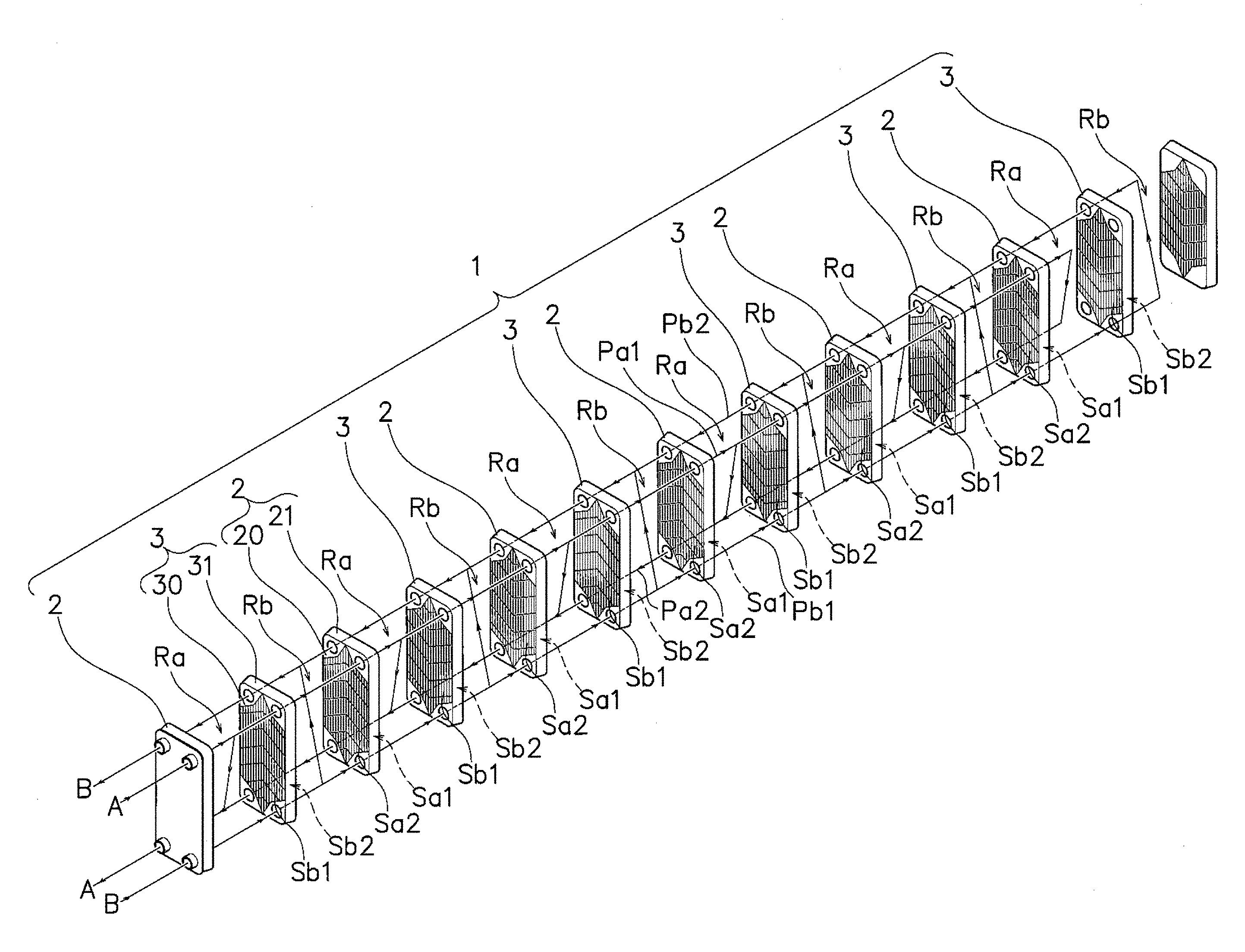
FIELD
[0002] The present invention relates to a plate heat exchanger that is used as a condenser and an evaporator.
BACKGROUND
[0003] Plate heat exchangers have been conventionally provided. A plate heat exchanger is a type of heat exchanger configured to exchange heat between a first fluid medium and a second fluid medium.
[0004] The plate heat exchanger includes a plurality of heat transfer plates. Each of the plurality of heat transfer plates includes a heat transfer portion. The heat transfer portion has a first surface on which ridges and valleys are formed, and a second surface that faces an opposite side to the first surface and on which valleys each serving as the back of each corresponding one of the ridges on the first surface and ridges located on the back of the respective valleys on the first surface are formed.
[0005] On each of the first surface and the second surface of the heat transfer portion, the ridges cross a centerline (hereinafter referred to as vertical centerline) that extends in a second direction orthogonal to a first direction. The ridges are formed over the entire length of the heat transfer portion in a third direction orthogonal to both the first direction and the second direction.
[0006] The plurality of heat transfer plates are stacked on each other in the first direction. That is, each of the plurality of heat transfer plates has the first surface of its heat transfer portion opposed to the first surface of the heat transfer portion of each adjacent heat transfer plate aligned on one side of the first direction. Each of the plurality of heat transfer plates has the second surface of its heat transfer portion opposed to the second surface of the heat transfer portion of the adjacent heat transfer plate aligned on the other side of the first direction. In this state, the ridges on the heat transfer portions of each two adjacent heat transfer plates cross and abut against each other. With this configuration, the valleys on the heat transfer portions form spaces between the heat transfer portions of each two adjacent heat transfer plates. That is, a first flow channel for circulating the first fluid medium in the second direction is formed between the first surfaces of the heat transfer portions of each two adjacent heat transfer plates. Also, a second flow channel for circulating the second fluid medium in the second direction is formed between the second surfaces of the heat transfer portions of each two adjacent heat transfer plates.
[0007] In the plate heat exchanger configured as above, the first fluid medium is circulated through the first flow channels in the second direction. The second fluid medium is circulated through the second flow channels in the second direction. As a result, the plate heat exchanger enables heat exchange between the first fluid medium within the first flow channels and the second fluid medium within the second flow channels, through the heat transfer portions that separate the first flow channels and the second flow channels (see, for example, Patent Literature 1).
[0008] There are some cases where the plate heat exchanger of this type is used as a condenser that is configured to condense the second fluid medium within the second flow channels through the heat exchange between the first fluid medium within the first flow channels and the second fluid medium within the second flow channels. There are also other cases where the plate heat exchanger of this type is used as an evaporator that is configured to evaporate the second fluid medium within the second flow channels through the heat exchange between the first fluid medium within the first flow channel and the second fluid medium within the second flow channels.
[0009] However, the conventional plate heat exchanger, if used as the condenser or the evaporator, has a limit in improving heat exchange performance due to the characteristics of the second fluid medium, which is the medium to be condensed or evaporated.
[0010] Specifically, the ridges on each of the heat transfer portions are formed crossing the vertical centerline of the heat transfer portion and extending over the entire length of the heat transfer portion in the third direction. This configuration causes the ridges of the heat, transfer portion to increase flow resistance of both the first flow channels and the second flow channels.
[0011] Generally, a fluid medium that does not cause phase change (a fluid medium having single-phase flow) is employed for the first fluid medium. Therefore, increase in the flow resistance in the first flow channels causes the heat transfer portions to be more likely to be subjected to thermal influences. The increase in the flow resistance in the first flow channels consequently becomes a factor for improved heat exchange performance.
[0012] In contrast, a fluid medium that causes phase change (a fluid medium having two-phase flow that contains liquid and gas), such as fluorocarbons, is employed for the second fluid medium. As a result, liquid film of the second fluid medium is formed on each of the second surfaces of the heat transfer portions that define the second flow channels. For the purpose of improving the heat transfer performance, therefore, it is necessary to increase the velocity of the second fluid medium and disturb flow of the liquid film formed on the second surface of the heat transfer portion.
[0013] However, the ridges on each the heat transfer portions are formed crossing the vertical centerline of the heat transfer portion and extending over the entire length of the heat transfer portion in the third direction. This configuration causes the ridges on the heat transfer portions to block flow of the second fluid medium within the second flow channels. That is, the ridges on the second surfaces of the heat transfer portions are formed so as to cross the flow of the second fluid medium within the second flow channels, and therefore increase the flow resistance of the second fluid medium within the second flow channels.
[0014] Therefore, the conventional plate heat exchanger has a limit in increasing the velocity of the second fluid medium within the second flow channels; and thus cannot sufficiently disturb the flow of the liquid film of the second fluid medium formed on the second surface of the heat transfer portion.
[0015] Hence, the conventional plate heat exchanger has a limit in improving the performance for transferring, to the heat transfer portion, heat of the second fluid medium that is circulated through the second flow channels.
CITATION LIST
Patent Literature
[0016] Patent Literature 1: JP 2001-099588 A
SUMMARY
Technical Problem
[0017] It is therefore an object of the present invention to provide a plate heat exchanger capable of improving performance for transferring, to the heat transfer portions, heat of the second fluid medium that causes the phase change as a result of its heat exchange with the first fluid medium.
Solution to Problem
[0018] The present invention features a plurality of heat transfer plates each including a heat transfer portion having a first surface on which ridges and valleys are formed, and a second surface that is opposed to the first surface and on which valleys being in a front-back relationship with the ridges of the first surface and ridges being in a front-back relationship with the valleys of the first surface are formed, the plurality of heat transfer plates respectively having the heat transfer portions stacked on each other in a first direction, wherein the first surface of the heat transfer portion of each of the plurality of heat transfer plates is arranged opposed to the first surface of the heat transfer portion of an adjacent heat transfer plate on one side in the first direction, and the second surface of the heat transfer portion of each of the plurality of heat transfer plates is arranged opposed to the second surface of the heat transfer portion of an adjacent heat transfer plate on an other side in the first direction, wherein a first flow channel through which a first fluid medium is circulated in a second direction orthogonal to the first direction is formed between the first surfaces of the heat transfer portions of each adjacent heat transfer plates, and a second flow channel through which a second fluid medium is circulated in the second direction is formed between the second surfaces of the heat transfer portions of each adjacent heat transfer plates, and wherein the heat transfer portion of at least one of each adjacent heat transfer plates includes: as the ridges formed on the first surface, at least one barrier ridge that crosses a centerline extending in the second direction of the heat transfer portion and is formed over the entire length in a third direction orthogonal to the first direction and the second direction of the heat transfer portion, and that divides the heat transfer portion into two or more divided areas in the second direction, the at least one barrier ridge crossing and abutting against the ridges formed on the first surface of the heat transfer portion of the opposed heat, transfer plate aligned adjacently and as the valleys formed on the second surface, a plurality of second flow channel forming valleys constituting part of the second flow channel, the plurality of second flow channel forming valleys being arranged at intervals from each other in the third direction in each of the two or more divided areas from one end to an other end in the second direction of each corresponding one of the two or more divided areas.
[0019] It is preferable that each of the heat transfer portions of the each adjacent heat transfer plates include: the at least one barrier ridge and the second flow channel forming valleys, as the valleys formed on the first surface, a plurality of first flow channel forming valleys constituting part of the first flow channel, the plurality of first flow channel forming valleys being arranged at intervals from each other in the third direction in each of the two or more divided areas from the one end to the other end in the second direction of each corresponding one of the two or more divided areas, and as the ridges formed on the first surface, a plurality of first flow channel side ridges each formed in the third direction between each adjacent first flow channel forming valleys, the first flow channel side ridges each extending from the one end to the other end in the second direction of each corresponding one of the two or more divided areas, and that the first flow channel side ridges in the mutually corresponding divided areas of the adjacent heat transfer plates be arranged with a clearance therebetween.
[0020] In this case, a projected amount of the at least one barrier ridge in the first direction may be set to be larger than a projected amount of the first flow channel side ridges in the first direction.
[0021] It is preferable that the plurality of first flow channel side ridges in the mutually corresponding divide areas of the each adjacent heat transfer plates be arranged while being displaced with each other in the third direction.
[0022] It is preferable that each of the heat transfer portions of the each adjacent heat transfer plates include: the at least one barrier ridge and the second flow channel forming valleys, and as the ridges formed on the second surface, a plurality of second flow channel side ridges each formed in the third direction between each adjacent second flow channel forming valleys, the second flow channel side ridges each extending from the one end to the other end of the divided area in the second direction, and that top ends of the second flow channel side ridges in the mutually corresponding divided areas of each adjacent heat transfer plates with the second surfaces of the heat transfer portions opposed to each other be in contact with each other.
[0023] It is preferable that each of the heat transfer portions of the each adjacent heat transfer plates include: the at least one barrier ridge and the second flow channel forming valleys, and as the ridges formed on the second surface, a plurality of second flow channel side ridges each formed in the third direction between each adjacent second flow channel forming valleys, the second flow channel side ridges each extending from the one end to the other end in the second direction of each corresponding one of the two or more divided areas, and that the second flow channel side ridges in the mutually corresponding divided areas of the each adjacent heat transfer plates with the second surfaces of the heat, transfer portions opposed to each other be arranged with a clearance therebetween.
[0024] In this case, the plurality of second flow channel side ridges in the mutually corresponding divided areas of the each adjacent heat transfer plates may be arranged while being displaced in the third direction.
[0025] It is preferable that the at least one barrier ridge include two or more harrier ridges provided at intervals in the second direction, and that the two or more barrier ridges divide each corresponding one of the heat transfer portions into three or more divided areas.
[0026] The barrier ridge may include at least one bent ridge portion that includes a pair of inclined ridge portions each having a proximal end and a distal end on an opposite side of the proximal end, the pair of inclined ridge portions being inclined in directions opposite to each other with respect to the centerline extending in the second direction or a virtual line parallel to the centerline, and having the distal ends thereof connected to each other.
[0027] It is preferable that each of the heat transfer portions of the each adjacent heat transfer plates include the barrier ridge having the bent ridge portion, and that the bent ridge portions of the barrier ridges of the each adjacent heat transfer plates be bent in directions completely opposite to each other and includes the inclined ridge portions of the bent ridge portions opposed to each other crossing and abutting against each other.
[0028] The barrier ridge may extend straightforwardly in the third direction.
[0029] Each of the heat transfer portions of the each adjacent heat transfer plates may include the barrier ridge extending in the third direction, and the barrier ridges of the each adjacent heat transfer plates may be arranged while being displaced with each other in the second direction.
BRIEF DESCRIPTION OF DRAWINGS
[0030] FIG. 1 is a perspective view of a plate heat exchanger according to one embodiment of the present invention.
[0031] FIG. 2 is an exploded perspective view of the plate heat exchanger according to the embodiment, which includes circulation routes of a first fluid medium and a second fluid medium.
[0032] FIG. 3 is a view of a heat transfer plate (first heat transfer plate) of the plate heat exchanger according to the embodiment, as seen from its first surface side.
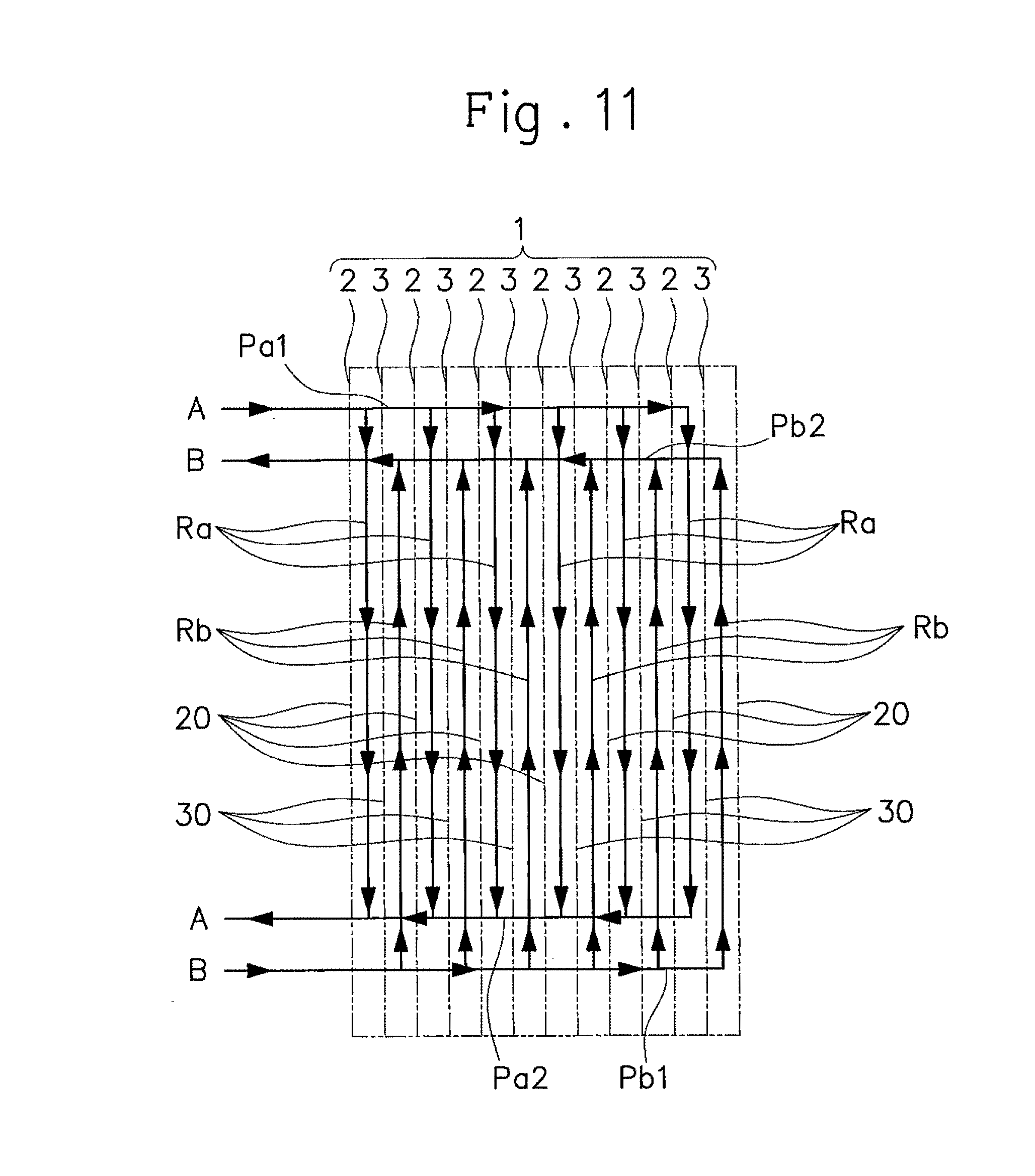
[0033] FIG. 4 is a view of the heat transfer plate (first heat transfer plate) of the plate heat exchanger according to the embodiment, as seen from its second surface side.
[0034] FIG. 5 is a view of a heat transfer plate (second heat transfer plate) of the plate heat exchanger according to the embodiment, as seen from its first surface side.
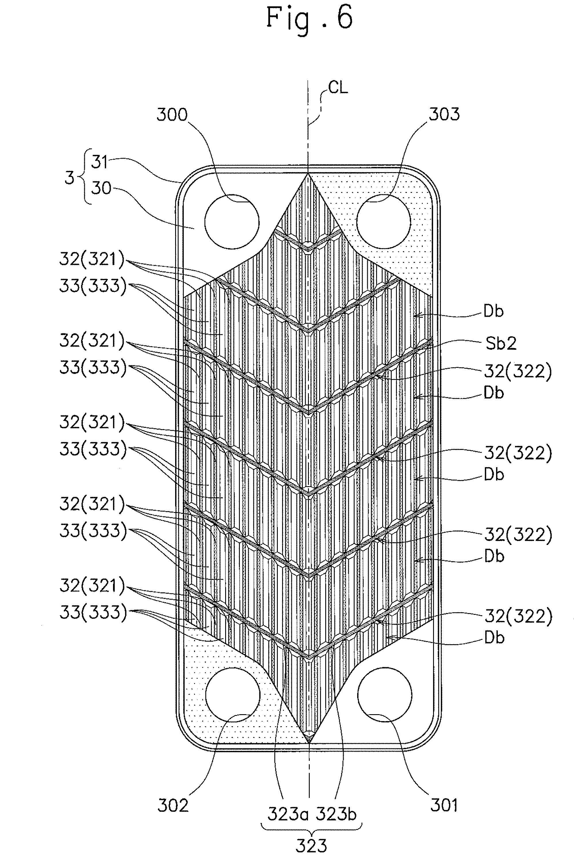
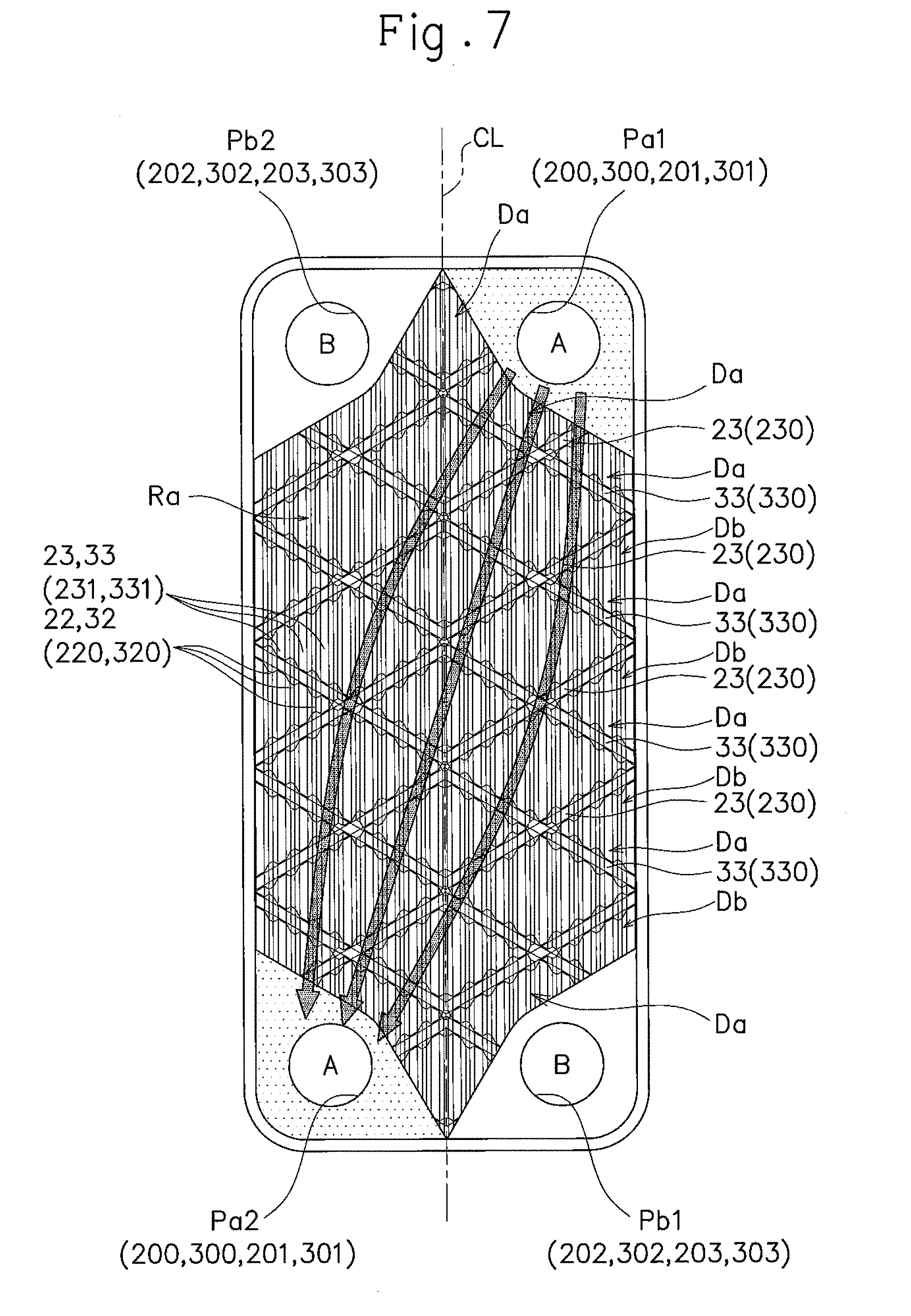
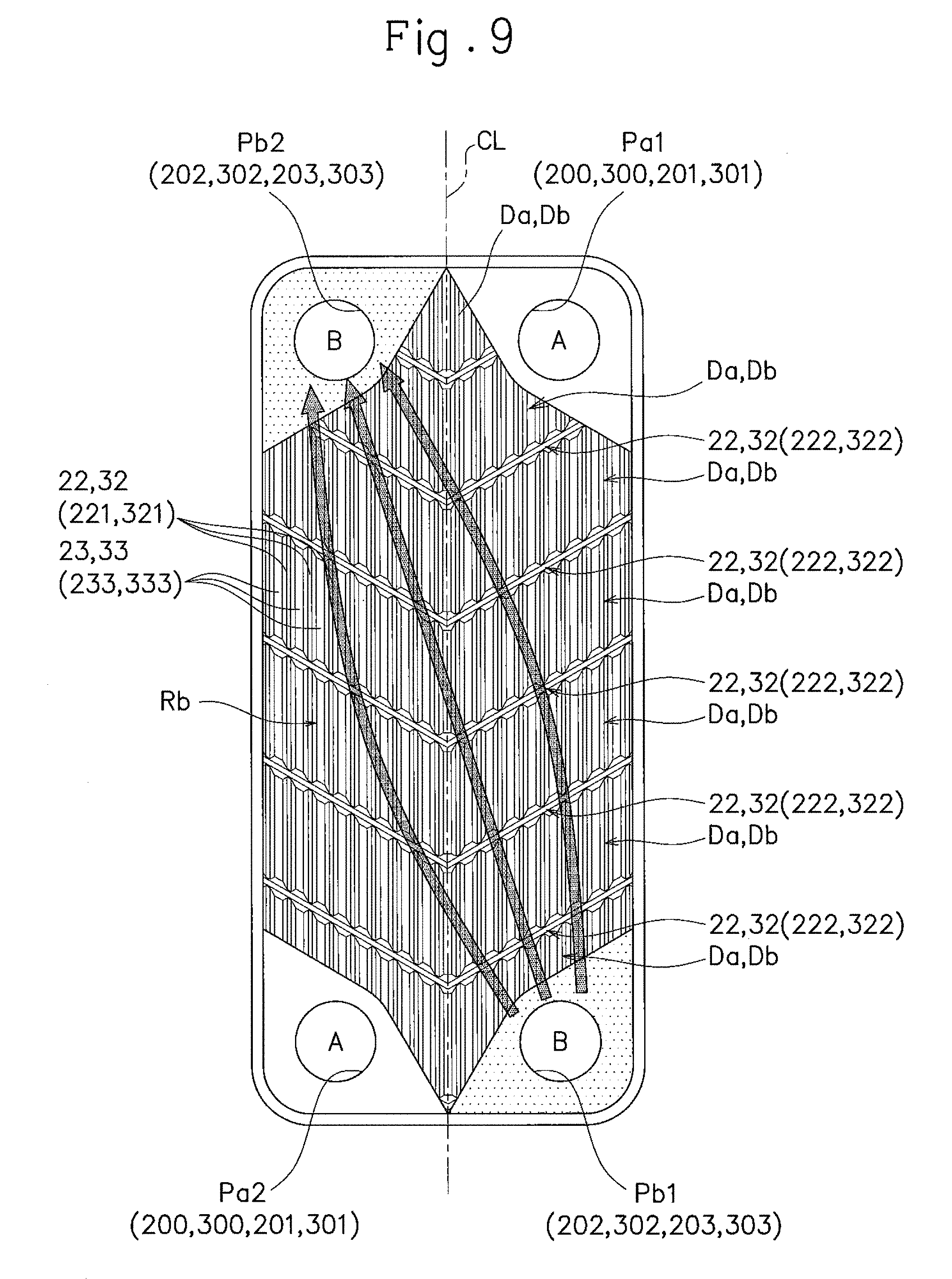
[0035] FIG. 6 is a view of the heat transfer plate (second heat transfer plate) of the plate heat exchanger according to the embodiment, as seen from its second surface side.
[0036] FIG. 7 is a view showing flows of the first fluid medium within a first flow channel in the plate heat exchanger according to the embodiment.
[0037] FIG. 8 is a schematic partial cross-sectional view of the plate heat exchanger according to the embodiment, showing a cross section taken along ridges on a second flow channel side thereof as seen from a third direction with the first flow channels mainly shown.
[0038] FIG. 9 is a view showing flows of the second fluid medium within the second flow channel in the plate heat exchanger according to the embodiment.
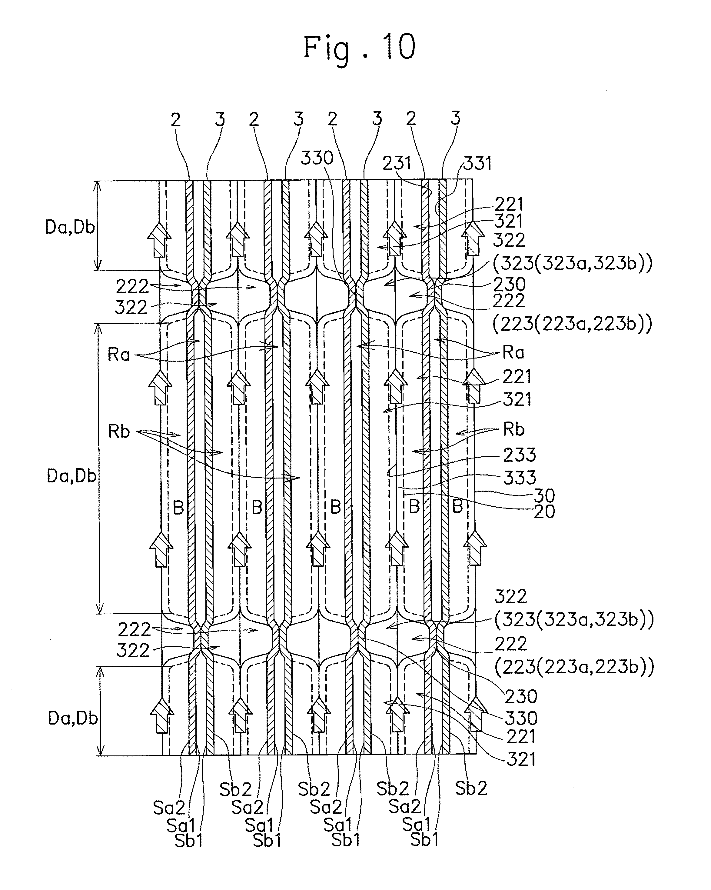
[0039] FIG. 10 is a schematic partial cross-sectional view of the plate heat exchanger according to the embodiment, showing a cross section taken along ridges on a first flow channel side thereof, as seen from the third direction with the second flow channels mainly shown.
[0040] FIG. 11 is a schematic diagram showing a circulation route of the first fluid medium through the first flow channels and a circulation route of the second fluid medium through the second flow channels of the plate heat exchanger according to the embodiment.
[0041] FIG. 12 is a view of a heat transfer plate (first heat transfer plate) of a plate heat exchanger according to another embodiment of the present invention, as seen from its first surface side.
[0042] FIG. 13 is a view of the heat transfer plate (first heat transfer plate) of the plate heat exchanger according to the other embodiment, as seen from its second surface side.
[0043] FIG. 14 is a view of a heat transfer plate (second heat, transfer plate) of the plate heat exchanger according to the other embodiment, as seen from its first surface side.
[0044] FIG. 15 is a view of the heat transfer plate (second heat transfer plate) of the plate heat exchanger according to the other embodiment, as seen from its second surface side.
[0045] FIG. 16 is a schematic diagram showing a circulation route of the first fluid medium through first flow channels and a circulation route of the second fluid medium through second flow channels, of a plate heat exchanger according to still another embodiment of the present invention.
[0046] FIG. 17 is a schematic diagram showing a circulation route of the first fluid medium through first flow channels and a circulation route of the second fluid medium through second flow channels, of a plate heat exchanger according to still another embodiment of the present invention.
DESCRIPTION OF EMBODIMENTS
[0047] Hereinafter, an embodiment of the present invention will be described with reference to the attached drawings.
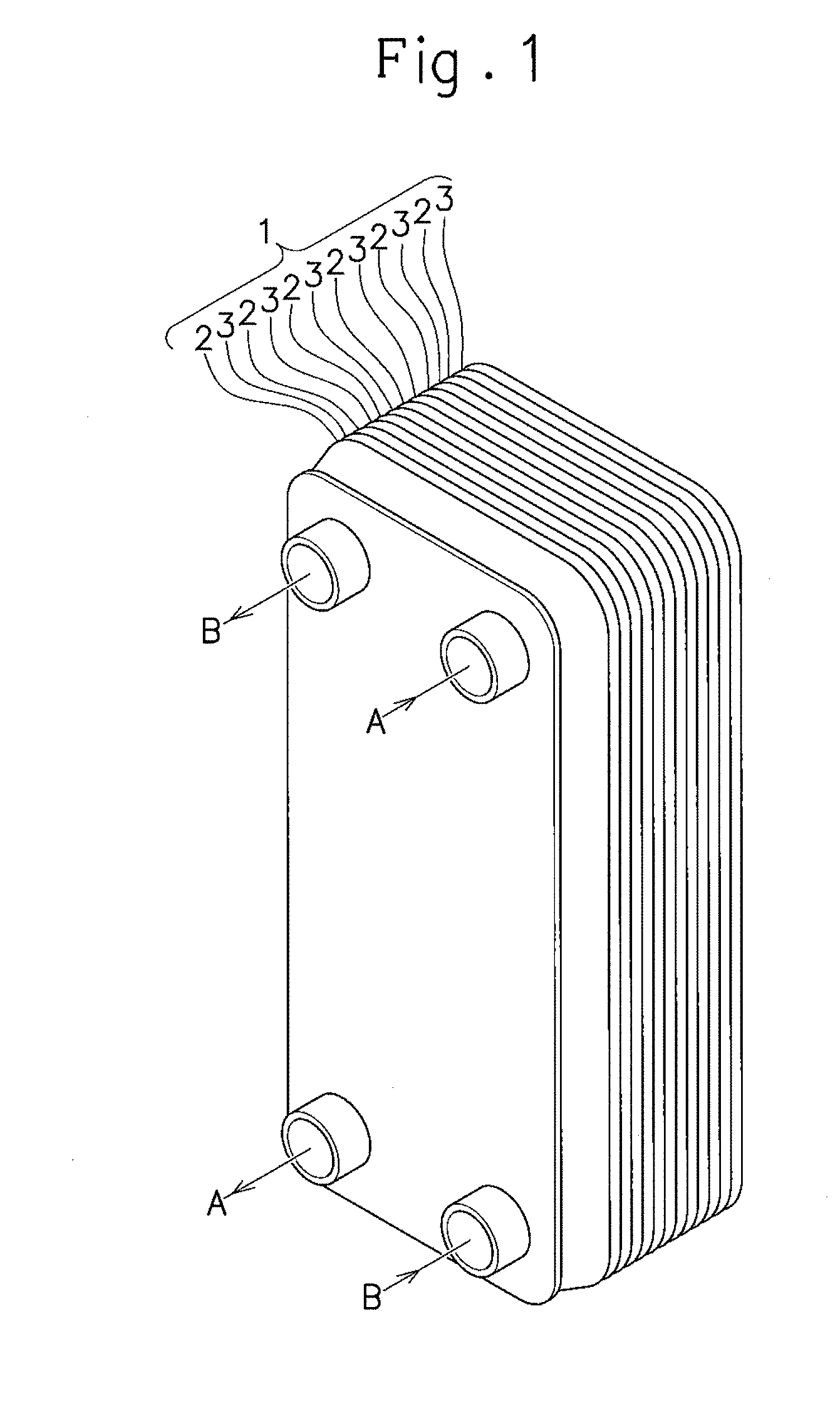
[0048] As shown in FIG. 1, a plate heat exchanger 1 includes a plurality of heat transfer plates 2, 3. That is, the plate heat exchanger 1 includes at least three heat transfer plates 2, 3. In this embodiment, the plate heat exchanger 1 includes more than three heat transfer plates 2, 3. Further, in this embodiment, the plurality of heat transfer plates 2, 3 include two kinds of heat transfer plates. Accordingly, in the following description, one kind of the heat transfer plate 2 out of the two kinds of heat transfer plates 2, 3 is referred to as a first heat transfer plate, and the other kind of the heat transfer plate 3 out of the two kinds of the heat transfer plates 2, 3 is referred to as a second heat transfer plate. However, the first heat transfer plate 2 and the second heat transfer plate 3 have a common configuration; therefore, for the sake of describing the common configuration, the first heat transfer plate 2 and the second heat transfer plate 3 are collectively referred to as the heat transfer plates 2, 3.
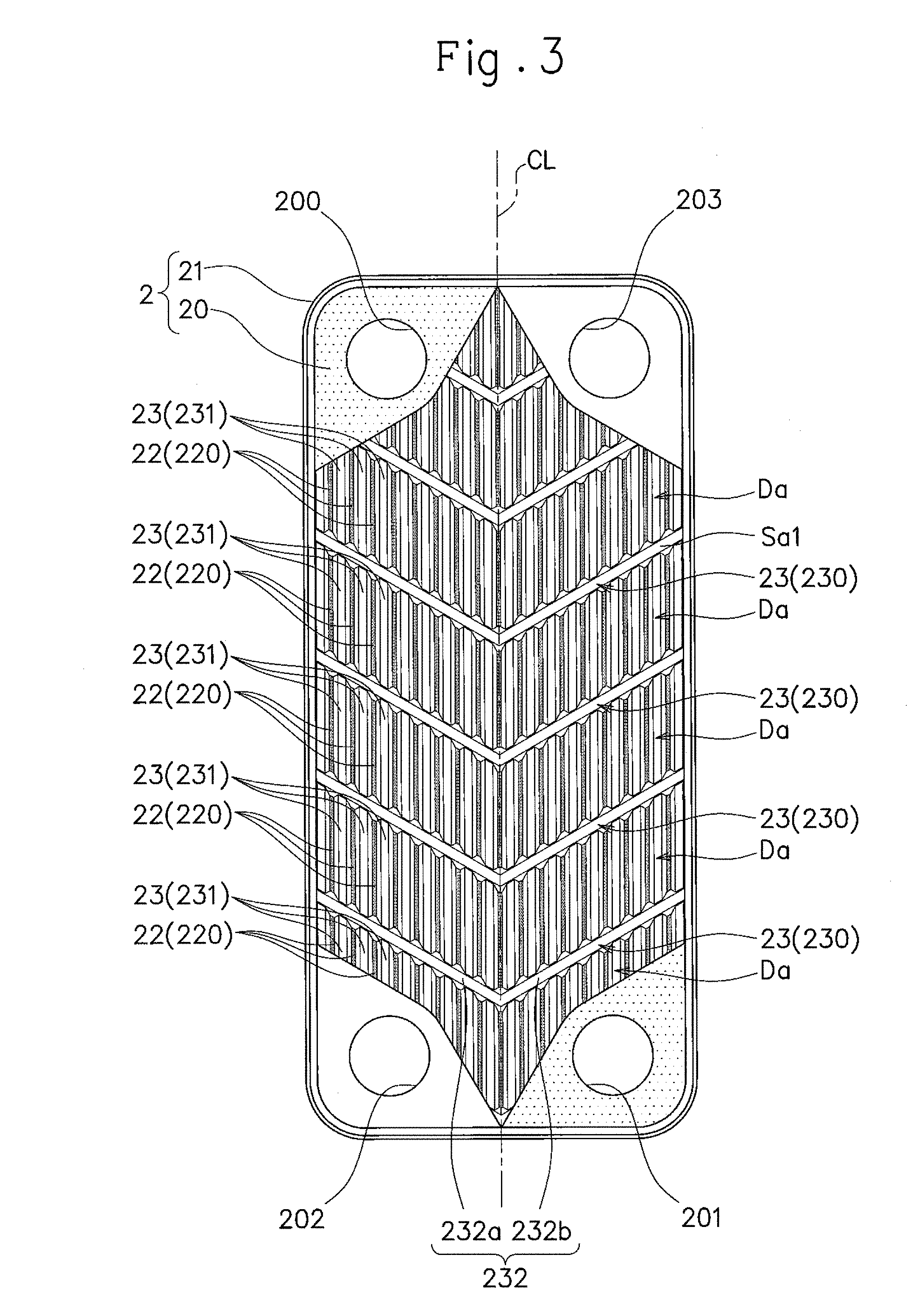
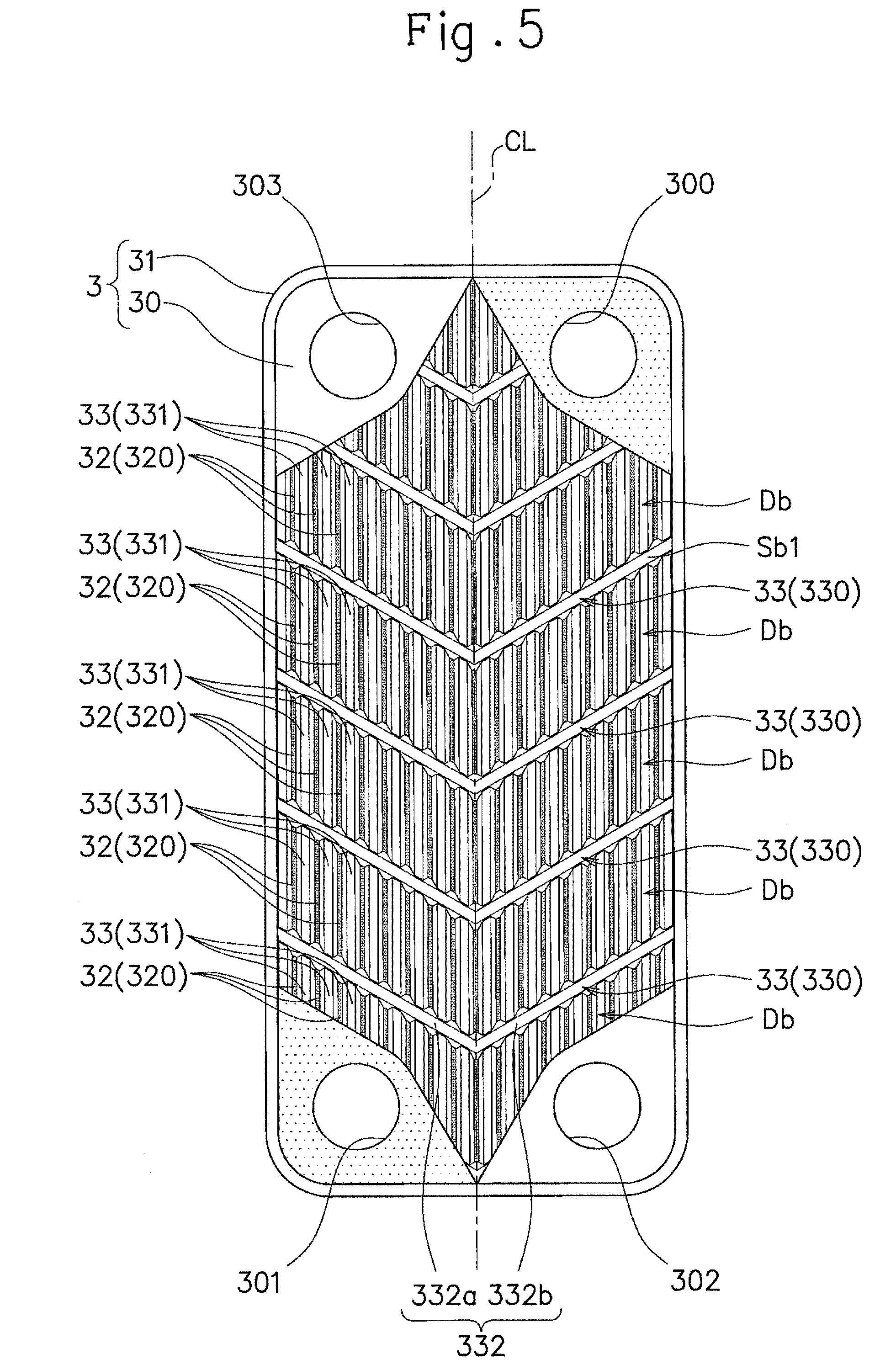
[0049] First, the common configuration of the first heat transfer plate 2 and the second heat transfer plate 3 will be described. As shown in FIG. 2, the heat transfer plates 2, 3 respectively include heat transfer portions 20, 30 that respectively have first surfaces Sa1, Sb1 and second surfaces Sa2, Sb2 facing opposite to the first surfaces Sa1, Sb1, and annular fitting portions 21, 31 that respectively extend from the entire outer peripheral edges of the heat transfer portions 20, 30 while having surfaces extending in a direction intersecting with the surfaces of the heat transfer portions 20, 30.
[0050] The heat transfer portions 20, 30 have a thickness in a first direction. Accordingly, the first surfaces Sa1, Sb1 and the second surfaces Sa2, Sb2 of the heat transfer portions 20, 30 are aligned in the first direction. As shown in FIG. 3 to FIG. 6, the heat transfer portions 20, 30 have an external form (contour) defined by a pair of long sides extending in a second direction orthogonal to the first direction, and a pair of short sides arranged with a distance from each other in the second direction while extending in a third direction orthogonal to the first direction and the second direction to connect the pair of long sides. That is, the heat, transfer portions 20, 30 have an external form having a rectangular shape with the long sides extending in the second direction, when seen from the first direction.
[0051] Each of the heat transfer portions 20, 30 has one end and the other end on the opposite side to the one end in the second direction. The heat transfer portions 20, 30 respectively have at least two openings 200, 201, 202, 203, 300, 301, 302, 303 in each of the one ends and the other ends in the second direction. In this embodiment, the heat transfer portions 20, 30 respectively have two openings 200, 203, 300, 303 in the one ends in the second direction, and two openings 201, 202, 301, 302 in the other ends in the second direction.
[0052] The two openings 200, 203, 300, 303 in the one ends in the second direction of the heat transfer portions 20, 30 are aligned in the third direction. The two openings 201, 202, 301, 302 in the other ends in the second direction of the heat transfer portions 20, 30 are aligned in the third direction.
[0053] An area surrounding each of the one openings 200, 300 in the one ends and an area surrounding each of the one openings 201, 301 in the other ends in the second direction of the heat transfer portions 20, 30 are recessed on the first surfaces Sa1, Sb1 side. Accordingly, an area surrounding each of the one openings 200, 300 in the one ends and an area surrounding each of the one openings 201, 301 in the other ends in the second direction of the heat transfer portions 20, 30 are projected on the second surfaces Sat, Sb2 side.
[0054] A projected amount of the area surrounding each of the openings 200, 201, 300, 301 that is projected on the second surfaces Sa2, Sb2 side is set so that the area surrounding each of the openings 200, 201, 300, 301 that is projected on the second surfaces Sat, Sb2 side abut against the area surrounding each corresponding one of the openings 200, 201, 300, 301 (the one openings 200, 300 in the one ends and the one openings 201, 301 in the other ends) in the heat transfer portions 20, 30 of each adjacent heat transfer plates 2, 3.
[0055] In contrast, an area surrounding each of the other openings 203, 303 in the one ends and an area surrounding each of the other openings 202, 302 in the other ends in the second direction of the heat transfer portions 20, 30 are projected on the first surfaces Sa1, Sb1 side. Accordingly, an area surrounding each of the other openings 203, 303 in the one ends and an area surrounding each of the other openings 202, 302 in the other ends in the second direction of the heat transfer portions 20, 30 are recessed on the second surfaces Sa2, Sb2 side.
[0056] A projected amount of the area surrounding each of the openings 202, 203, 302, 303 that is projected on the first surfaces Sa1, Sb1 side is set so that the area surrounding each of the openings 202, 203, 302, 303 that is projected on the first surfaces Sa1, Sb1 side abut the area surrounding each corresponding one of the openings 202, 203, 302, 303 (the other openings 202, 302 in the one ends and the other openings 203, 303 in the other ends) in the heat transfer portions 20, 30 of each adjacent heat transfer plates 2, 3. In FIG. 3 and FIG. 4, recessed areas out of the areas each surrounding the openings 200, 201, 202, 203, 300, 301, 302, 303, and bottom parts of valleys 22, 32, which will be described later, are shown in stippling to allow the relationship between the projected portions and the recessed portions of the first surfaces Sa1, Sb1 and the second surfaces Sa2, Sb2 to be distinguishable.
[0057] In this embodiment, the one openings 200, 300 in the one ends and the one openings 201, 301 in the other ends in the second direction of the heat transfer portions 20, 30 are located diagonal to each other, due to the configuration in which the heat transfer plates 2, 3 are stacked on each other. The other openings 203, 303 in the one ends and the other openings 202, 302 in the other ends in the second direction of the heat transfer portions 20, 30 are also located diagonal to each other.
[0058] The valleys 22, 32 and ridges 23, 33 are respectively formed on each of the first surfaces Sa1, Sb1 and the second surfaces Sa2, Sb2 of the heat transfer portions 20, 30. Each of the first surfaces Sa1, Sb1 and the second surfaces Sa2, Sb2 of the heat, transfer portions 20, 30 has a plurality (a large number) of valleys 22, 32 and a plurality (a large number) of ridges 23, 33.
[0059] More specifically, each of the heat transfer plates 2, 3 is formed by press molding of a metal plate. Accordingly the valleys 22, 32 formed on the first surfaces Sa1, Sb1 of the heat transfer portions 20, 30 are in a front-back relationship with the ridges 23, 33 formed on the second surfaces Sa2, Sb2 of the heat transfer portions 20, 30. The ridges 23, 33 formed on the first surfaces Sa1, Sb1 of the heat transfer portions 20, 30 are in a front-back relationship with the valleys 22, 32 formed on the second surfaces Sa2, Sb2 of the heat, transfer portions 20, 30. That is, the deformation of the metal plate by press molding allows the valleys 22, 32 formed on the first surfaces Sa1, Sb1 of the heat transfer portions 20, 30 to be formed at positions corresponding to the positions of the ridges 23, 33 formed on the second surfaces Sa2, Sb2 of the heat transfer portions 20, 30. Also, the deformation of the metal plate by press molding allows the ridges 23, 33 formed on the first surfaces Sa1, Sb1 of the heat transfer portions 20, 30 to be formed at positions corresponding to the positions of the valleys 22, 32 formed on the second surfaces Sa2, Sb2 of the heat, transfer portions 20, 30.
[0060] As shown in FIG. 3 and FIG. 5, the heat transfer portion 20, 30 includes, as the ridges 23, 33 formed on the first surface Sa1, Sb1, at least one barrier ridge 230, 330 that crosses a centerline CL extending in the second direction (hereinafter referred to as vertical centerline) and is formed over the entire length in the third direction, and that divides the heat transfer portion 20, 30 into two or more divided areas Da, Db in the second direction, the barrier ridge 230, 330 crossing and abutting against the ridge 23, 33 formed on the first surface Sa1, Sb1 of the opposed heat transfer portion 20, 30.
[0061] The heat transfer portion 20, 30 includes, as the valleys 22, 32 formed on the first surface Sa1, Sb1, a plurality of first flow channel forming valleys 220, 320 that constitute part of a first flow channel Ra, the plurality of first flow channel forming valleys 220, 320 being arranged in each of the two or more divided areas Da, Db from one end to the other end of the divided area Da, Db in the second direction at intervals from each other in the third direction.
[0062] The heat transfer portion 20, 30 includes, as the ridges 23, 33 formed on the first surface Sa1, Sb1, a plurality of first flow channel side ridges 231, 331 formed by extending in the second direction between each adjacent first flow channel forming valleys 220, 320 in the third direction.
[0063] In this embodiment, two or more barrier ridges 230, 330 are provided at intervals from each other in the second direction. The two or more barrier ridges 230, 330 divide the heat transfer portion 20, 30 into three or more divided areas Da, Db.
[0064] The barrier ridges 230, 330 include at least one bent ridge portion 232, 332. The bent ridge portion 232, 332 includes a pair of inclined ridge portions 232a, 232b, 332a, 332b each portion having a proximal end and a distal end on the opposite side of the proximal end, the pair of inclined ridge portions 232a, 232b, 332a, 332b being inclined in a direction opposite to each other with respect to the vertical centerline CL and having the distal ends thereof connected to each other. In this embodiment, the barrier ridges 230, 330 have one bent ridge portion 232, 332.
[0065] In this embodiment, the proximal ends of the pair of inclined ridge portions 232a, 232b, 332a, 332b that constitute the bent ridge portion 232, 332 are located on an end edge in the third direction of the heat transfer portion 20, 30.
[0066] In contrast, the distal ends of the pair of inclined ridge portions 232a, 232b, 332a, 332b are located at the center (on the vertical centerline CL) in the third direction of the heat transfer portion 20, 30. With this, the distal ends of the pair of inclined ridge portions 232a, 232b, 332a, 332b are connected in face-to-Pace relationship.
[0067] This configuration allows the barrier ridge 230, 330 itself to constitute the bent ridge portion 232, 332 in this embodiment. The pair of inclined ridge portions 232a, 232b, 332a, 332b are symmetrically arranged with reference to a virtual line that extends in the second direction. That is, the pair of inclined ridge portions 232a, 232b, 332a, 332b are inclined in a direction completely opposite to each other. However, the pair of inclined ridge portions 232a, 232b, 332a, 332b have the same inclination angle with respect, to the vertical centerline CL extending in the second direction.
[0068] A projected amount in the first direction of the barrier ridges 230, 330 is set to be larger than that of the first flow channel side ridges 231, 331. Accordingly, top ends of the barrier ridges 230, 330 are positioned outwardly of the top ends of the first flow channel side ridges 231, 331. This configuration allows only the barrier ridges 230, 330 out of the ridges 23 formed on the first surface Sa1, Sb1 of the heat transfer portion 20, 30 to contact the heat transfer portion 20, 30 of the opposed heat transfer plate 2, 3. That is, the first flow channel side ridges 231, 331 are formed to have a lower height than the barrier ridges 230, 330 so that they do not contact the opposed heat transfer plate 2, 3.
[0069] The first flow channel forming valleys 220, 320 and the first flow channel side ridges 231, 331 formed in each of the divided areas Da, Db are formed over the entire length in the second direction of the divided areas Da, Db. Accordingly, at least one end of each of the first flow channel forming valleys 220, 320 and at least one end of each of the first flow channel side ridges 231, 331 are joined to a corresponding one of the barrier ridges 230, 330 that define the divided areas Da, Db. That is, the one ends of the first flow channel forming valleys 220, 320 and the first flow channel side ridges 231, 331 respectively are joined to one of each pair of barrier ridges 230, 330 that define the divided areas Da, Db. In contrast, the other ends of the first flow channel forming valleys 220, 320 and the first flow channel side ridges 231, 331 are joined to the other one of each pair of barrier ridges 230, 330 that define the divided areas Da, Db.
[0070] In this embodiment, the plurality of first flow channel forming valleys 220, 320 formed in each of the two or more divided areas Da, Db are aligned with each other in the second direction. That is, the first flow channel forming valleys 220, 320 formed in the two or more divided areas Da, Db correspond in the number and arrangement to each other. Accordingly, the first flow channel side ridges 231, 331 formed in the two or more divided areas Da, Db also correspond in the number and arrangement to each other.
[0071] As shown in FIG. 4 and FIG. 6, the heat transfer portion 20, 30 includes, as the valleys 22, 32 formed on the second surface 5a2, Sb2, valleys (hereinafter referred to as back side valleys) 222, 322 formed respectively on the back sides of the barrier ridges 230, 330 on the first surface Sa1, Sb1.
[0072] The heat transfer portion 20, 30 include, as the valleys 22, 32 formed on the second surface Sa2, Sb2, a plurality of second flow channel forming valleys 221, 321 that constitute part of a second flow channel Rb, the plurality of second flow channel forming valleys 221, 321 being arranged in each of the two or more divided areas Da, Db from one end to the other end of the divided area Da, Db in the second direction at intervals from each other in the third direction. Further, the heat transfer portion 20, 30 includes, as the ridges 23, 33 formed on the second surface Sa2, Sb2, a plurality of second flow channel side ridges 233, 333 formed in the third direction between each adjacent second flow channel forming valleys 221, 321, the second flow channel side ridges 233, 333 each extending from one end to the other end in the second direction of the divided area Da, Db.
[0073] The back side valleys 222, 322 are formed in the same pattern as the barrier ridges 230, 330 except that they have a reversed concavo-convex relationship. On the second surface Sa2, Sb2 of the heat transfer portion 20, 30, therefore, a bent valley portion 223, 323 that includes a pair of inclined valley portions 223a, 223b, 323a, 323b is formed, which is the valley 22, 32 formed on the back side of each pair of inclined ridge portions 232a, 232b, 332a, 332b.
[0074] In this embodiment, the bent ridge portion 232, 332 (the pair of inclined ridge portions 232a, 232b, 332a, 332b) constitutes the barrier ridge 230, 330. Thus, the bent valley portion 223, 323 constitutes each of the entire back side valleys 222, 322 formed on the back side of each of the barrier ridges 230, 330.
[0075] The second flow channel forming valleys 221, 321 are the valleys 22, 32 formed on the back sides of the first flow channel side ridges 231, 331 on the first surface Sa1, Sb1. The second flow channel forming valleys 221, 321 are herein described specifically. As described above, the second flow channel forming valleys 221, 321 extend from one end to the other end in the second direction of each of the divided areas Da, Db. Here, "extend from one end to the other end in the second direction" means that the second flow channel forming valleys 221, 321 extend from one end to the other end in the second direction of each of the divided areas Da, Db at a smaller angle with respect to the virtual line extending in the second direction than an inclination angle with respect to a virtual line extending in the third direction. In this embodiment, the second flow channel forming valleys 221, 321 extend in the second direction. That is, in this embodiment, the second flow channel forming valleys 221, 321 extend at an angle of 0 degree with respect to the virtual line extending in the second direction and an angle of 90 degrees with respect to the virtual line extending in the third direction.
[0076] With this configuration, the second flow channel side ridges 233, 333 each being formed between each adjacent second flow channel forming valleys 221, 321 also extend in the second direction. The internal surfaces that define the second flow channel forming valleys 221, 321 are continuous with the external surfaces that define the second flow channel side ridges 233, 333. With this configuration, the second surface Sa2, Sb2 (the divided areas Da, Db) of the heat transfer portion 20, 30 has a corrugated shape with projections and recesses aligned in the third direction.
[0077] The second flow channel forming valleys 221, 321 and the second flow channel side ridges 233, 333 are formed over the entire length in the second direction of each of the divided areas Da, Db. The second flow channel forming valleys 221, 321 are thus continuous with the back side valleys 222, 322 formed on the backs of the barrier ridges 230, 330 that define the divided areas Da, Db in which the second flow channel forming valleys 221, 321 themselves are formed. That is, each of the second flow channel forming valleys 221, 321 is open to the inside of a corresponding one of the back side valleys 222, 322.
[0078] The first heat transfer plates 2 and the second heat transfer plates 3 respectively include the heat transfer portions 20, 30 configured as above. The first heat transfer plates 2 and the second heat transfer plates 3 are stacked on each other so that their second surfaces Sa2, Sb2 are opposed to each other while their first surfaces Sa1, Sb1 are opposed to each other. As shown in FIG. 3, therefore, each of the first heat transfer plates 2 includes the fitting portion 21 projecting on the first surface Sa1 side of the heat transfer portion 20. In contrast, as shown in FIG. 6, each of the second heat transfer plates 3 includes the fitting portion 31 projecting on the second surface Sb2 side of the heat transfer portion 30.
[0079] Each of the plurality of heat transfer plates 2, 3 (the first heat transfer plates 2 and the second heat, transfer plates 3) has been described as above. The plurality of heat transfer plates 2, 3 (the first heat, transfer plates 2 and the second heat transfer plates 3) are stacked on each other in the first direction, as shown in FIG. 2. In this embodiment, the first heat transfer plates 2 and the second heat transfer plates 3 are alternately stacked on each other in the first direction.
[0080] With this configuration, each of the plurality of heat transfer plates 2, 3 has the first surface Sa1, Sb1 of its heat transfer portion 20, 30 opposed to the first surface Sa1, Sb1 of the heat transfer portion 20, 30 of the adjacent heat, transfer plate 2, 3 on one side in the first direction. Further, each of the plurality of heat transfer plates 2, 3 has the second surface Sa2, Sb2 of its heat transfer portion 20, 30 opposed to the second surface Sa2, Sb2 of the heat transfer portion 20, 30 of the adjacent heat transfer plate 2, 3 on the other side in the first direction.
[0081] In this embodiment, as shown in FIG. 7, the plurality of heat transfer plates 2, 3 are stacked on each other so that the distal ends of the inclined ridge portions 232a, 232b of the barrier ridge(s) 230 (the bent ridge portion(s) 232) of each of the first heat transfer plates 2 are located closer to one end in the second direction of the heat transfer portion 20 than the proximal ends thereof, whereas the distal ends of the inclined ridge portions 332a, 332b of the barrier ridge(s) 330 (the bent ridge portion(s) 332) of each of the second heat, transfer plates 3 are located closer to the other end in the second direction of the heat transfer portion 30 than the proximal ends thereof.
[0082] That is, as shown in FIG. 7 and FIG. 8, the first heat transfer plates 2 and the second heat transfer plates 3 are stacked alternately on each other so that one inclined ridge portion 232a constituting the barrier ridge 230 (the bent ridge portion 232) of each of the first heat transfer plates 2 crosses and abuts against one inclined ridge portion 332a constituting the barrier ridge 330 (the bent ridge portion 332) of each of the second heat transfer plates 3, and that the other inclined ridge portion 232b constituting the barrier ridge 230 (the bent ridge portion 232) of each of the first heat transfer plates 2 crosses and abuts against the other inclined ridge portion 332b constituting the barrier ridge 330 (the bent ridge portion 332) of each of the second heat transfer plates 3.
[0083] In this embodiment, as shown in FIG. 2, each of the first heat transfer plates 2 and each of the second heat transfer plates 3 are stacked on each other to form a pair while their back side valleys 222, 322 are opposed to each other. When a plurality of pairs are stacked, every other pair is turned 180 degrees upside down about a virtual line extending in the first direction. In this state, the fitting portion 21, 31 of one heat transfer plate 2, 3 (the first heat transfer plate 2 or the second heat transfer plate 3) out of the heat transfer plates 2, 3 adjacent to each other in the first direction is fitted onto the fitting portion 21, 31 of the other heat transfer plate 2, 3 (the first heat transfer plate 2 or the second heat transfer plate 3) out of the heat transfer plates 2, 3 adjacent to each other in the first direction.
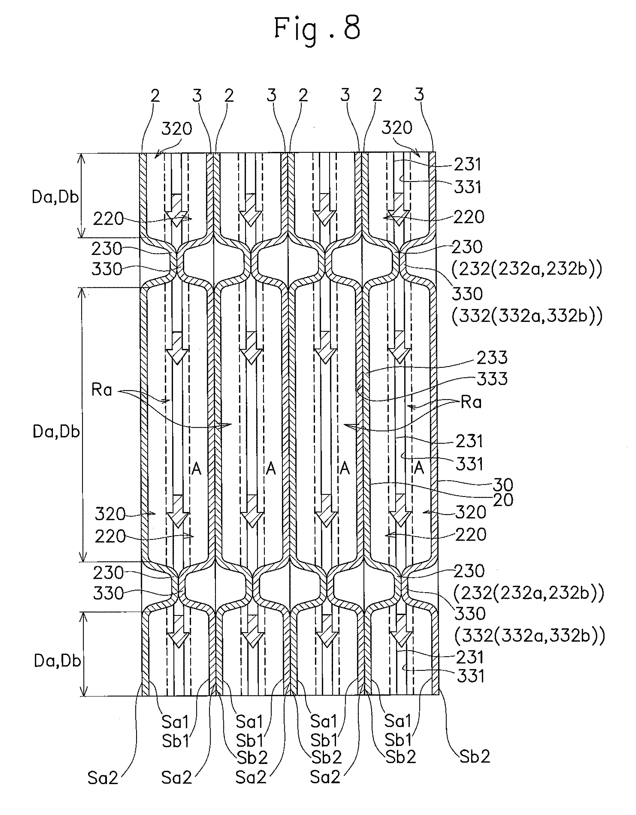
[0084] As shown in FIG. 7, the first flow channel side ridges 231, 331 in the mutually corresponding divided areas Da, Db of each adjacent heat transfer plates 2, 3 (the first heat transfer plate 2 and the second heat transfer plate 3) with their first surfaces Sa1, Sb1 of the heat transfer portions 20, 30 opposed to each other are arranged to overlap each other when seen from the first direction. As shown in FIG. 8, the first flow channel side ridges 231, 331 in the mutually corresponding divided areas Da, Db of each adjacent heat transfer plates 2, 3 (the first heat transfer plate 2 and the second heat transfer plate 3) with their first surfaces Sa1, Sb1 on the heat transfer portions 20, 30 opposed to each other are located at intervals from each other.
[0085] As shown in FIG. 9, the second flow channel side ridges 233, 333 in the mutually corresponding divided areas Da, Db of each adjacent heat transfer plates 2, 3 (the first heat transfer plate 2 and the second heat transfer plate 3) with their second surfaces Sa2, Sb2 of the heat transfer portions 20, 30 opposed to each other are arranged to overlap each other when seen from the first direction. As shown in FIG. 10, each adjacent heat transfer plates 2, 3 (the first heat transfer plate 2 and the second heat transfer plate 3) with the second surfaces Sa2, Sb2 of the heat transfer portions 20, 30 opposed to each other have the top ends of the second flow channel side ridges 233, 333 in the mutually corresponding divided areas Da, Db contacting each other.
[0086] With this configuration, as shown in FIG. 2, the first flow channel Ra through which the first fluid medium A is circulated in the second direction orthogonal to the first direction is formed between the first surfaces Sa1, Sb1 of the heat transfer portions 20, 30 of each adjacent heat transfer plates 2, 3. The second flow channel Rb through which the second fluid medium B is circulated in the second direction is also formed between the second surfaces Sa2, Sb2 of the heat transfer portions 20, 30 of each adjacent heat transfer plates 2, 3.
[0087] Further, as described above, the plurality of heat transfer plates 2, 3 are stacked on each other in the first direction so that the openings 200, 201, 202, 203, 300, 301, 302, 303 located in the corresponding positions of the heat transfer portions 20, 30 are lined up in the first direction. The areas respectively surrounding the openings 200, 201, 202, 203, 300, 301, 302, 303 that are opposed to and projected toward each other abut each other. This configuration forms a first inflow channel Pa1 for supplying the first fluid medium A into the first flow channels Ra, a first outflow channel Pa2 for causing the first fluid medium A to flow out of the first flow channels Ra, a second inflow channel Pb1 for supplying the second fluid medium B into the second flow channels Rb, and a second outflow channel Pb2 for causing the second fluid medium B to flow out of the second flow channels Rb.
[0088] In the plate heat exchanger 1 according to this embodiment, the abutted portions between the adjacent heat transfer plates 2, 3 are brazed together. This configuration allows the plurality of heat transfer plates 2, 3 to be integrally (mechanically) connected to each other, and an interface between the opposed surfaces (abutted portions) of the adjacent heat transfer plates 2, 3 to be sealed.
[0089] The plate heat exchanger 1 according to this embodiment has been described as above. As shown in FIG. 2, FIG. 7, and FIG. 11, the first fluid medium A flows from the first inflow channel Pa1 into the plurality of first flow channels Ra. The first fluid medium A is circulated through each of the first flow channels Ra in the second direction, and flows out to the first outflow channel Pa2. In contrast, as shown in FIG. 2, FIG. 9, and FIG. 11, the second fluid medium B flows from the second inflow channel Pb1 into the plurality of second flow channels Rb. The second fluid medium B is circulated through each of the second flow channels Rb in the second direction, and flows out to the second outflow channel Pb2.
[0090] In this embodiment, as shown in FIG. 7, the first fluid medium A is circulated through each of the first flow channels Ra with a diagonal line connecting opposing corners of the heat transfer portion 20, 30 as a center of flow. As shown in FIG. 9, in contrast, the second fluid medium B is circulated through each of the second flow channels Rb with another diagonal line connecting opposing corners of the heat transfer portion 20, 30 as a center of flow, which is different from the diagonal line being the center of the flow of the first fluid medium A.
[0091] At this time, the first fluid medium A that is circulated through the first flow channels Ra and the second fluid medium B that is circulated through the second flow channels Rb exchange heat via the heat transfer plates 2, 3 (the heat transfer portions 20, 30) that separate the first flow channels Ra and the second flow channels Rb. As a result, the second fluid medium B is condensed or evaporated in the course of being circulated through the second flow channels Rb in the second direction.
[0092] As just described, the plate heat exchanger 1 according to this embodiment includes: a plurality of heat transfer plates 2, 3 each including a heat transfer portion 20, 30 having a first surface Sa1, Sb1 on which ridges 23, 33 and valleys 22, 32 are formed, and a second surface Sat, Sb2 that is opposed to the first surface Sa1, Sb1 and on which valleys 22, 32 being in a front-back relationship with the ridges 23, 33 of the first surface Sa1, Sb1 and ridges 23, 33 being in a front-back relationship with the valleys 22, 32 of the first surface Sa1, Sb1 are formed, the plurality of heat transfer plates 2, 3 respectively having the heat transfer portions 20, 30 stacked on each other in a first direction, wherein the first surface Sa1, Sb1 of the heat transfer portion 20, 30 of each of the plurality of heat transfer plates 2, 3 is arranged opposed to the first surface Sa1, Sb1 of the heat transfer portion 20, 30 of an adjacent heat transfer plate 2, 3 on one side in the first direction, and the second surface Sa2, Sb2 of the heat transfer portion 20, 30 of each of the plurality of heat transfer plates 2, 3 is arranged opposed to the second surface Sa2, Sb2 of the heat transfer portion 20, 30 of an adjacent heat transfer plate 2, 3 on an other side in the first direction, wherein a first flow channel Ra through which a first fluid medium A is circulated in a second direction orthogonal to the first direction is formed between the first surfaces Sa1, Sb1 of the heat transfer portions 20, 30 of each adjacent heat transfer plates 2, 3, and a second flow channel Rb through which a second fluid medium B is circulated in the second direction is formed between the second surfaces Sa2, Sb2 of the heat transfer portions 20, 30 of each adjacent heat transfer plates 2, 3, and wherein the heat transfer portion 20, 30 of at least one of each adjacent heat transfer plates 2, 3 includes: as the ridges 23, 33 formed on the first surface Sa1, Sb1, at least one barrier ridge 230, 330 that crosses a centerline (vertical centerline) CL extending in the second direction of the heat transfer portion 20, 30 and is formed over the entire length in a third direction orthogonal to the first direction and the second direction of the heat transfer portion 20, 30, and that divides the heat transfer portion 20, 30 into two or more divided areas Da, Db in the second direction, the at least one barrier ridge 230, 330 crossing and abutting against the ridges 23, 33 formed on the first surface Sa1, Sb1 of the heat transfer portion 20, 30 of the opposed heat transfer plate 2, 3, and as the valleys 22, 32 formed on the second surface Sa2, Sb2, a plurality of second flow channel forming valleys 221, 321 constituting part of the second flow channel Rb, the plurality of second flow channel forming valleys 221, 321 being arranged at intervals from each other in the third direction in each of the two or more divided areas Da, Db from one end to an other end in the second direction of each corresponding one of the two or more divided areas Da, Db.
[0093] According to the plate heat exchanger 1 configured as above, the barrier ridges 230, 330 are projected toward the opposed heat transfer portion 20, 30 at intermediate positions of the first flow channel Ra formed between the first surfaces Sa1, Sb1 of each adjacent heat transfer portions 20, 30 (see FIG. 8). This configuration allows the barrier ridges 230, 330 to block circulation of the first fluid medium A through the first flow channels Ra to thereby increase the circulating resistance of the first fluid medium A through the first flow channels Ra. As a result, the first fluid medium A is more likely to thermally influence the heat transfer portions 20, 30, which consequently enhances heat transfer performance to the second fluid medium B side.
[0094] The valleys 22, 32 on the first surface Sa1, Sb1 are in a front-back relationship with the ridges 23, 33 on the second surface Sa2, Sb2, and the ridges 23, 33 on the first surface Sa1, Sb1 are in a front-back relationship with the valleys 22, 32 on the second surface Sa2, Sb2. Accordingly the back side valleys 222, 322 corresponding to the barrier ridges 230, 330 are formed on the second surface 5a2, Sb2 of the heat transfer portion 20, 30. That is, the back side valleys 222, 322 crossing a centerline (vertical centerline) CL that extends in the second direction of the heat transfer portion 20, 30 are formed on the second surface Sa2, Sb2 of the heat transfer portion 20, 30. This configuration allows the back side valley(s) 222, 322 to divide the heat transfer portion 20, 30 into two or more divided areas Da, Db on the second surface Sa2, Sb2 side.
[0095] The plurality of second flow channel forming valleys 221, 321 extend from one end to the other end in the second direction of each of the divided areas Da, Db in which they are located. The plurality of second flow channel forming valleys 221, 321 are continuous with the back side valleys 222, 322 (the valleys 22, 32 corresponding to the barrier ridges 230, 330) that define the divided areas Da, Db in which they are located. As a result, the second flow channel Rb has nothing that blocks circulation of the second fluid medium B (i.e. that crosses the flow channel) over the entire length in the second direction.
[0096] The second flow channel forming valleys 221, 321 extend from one end to the other end in the second direction of each of the divided areas Da, Db, Thus, the second flow channel forming valleys 221, 321 extend straightforwardly in the second direction, or extend while being inclined in the state where an inclination component (angle) with respect to a virtual line extending in the second direction is smaller than an inclination component (angle) with respect to a virtual line extending in the third direction. This configuration allows the second flow channel forming valleys 221, 321 to form space (part of the second flow channel Rb) corresponding to or substantially corresponding to the circulating direction of the second fluid medium B. Consequently, the circulating resistance of the second fluid medium B through the second flow channel Rb can be reduced to increase the velocity of the second fluid medium B.
[0097] As a result, liquid film of the second fluid medium B formed on the surfaces of the heat, transfer portions 20, 30 is disturbed by the increased velocity of the second fluid medium B, even if a fluid medium that causes phase change (a fluid medium having two-phase flow that contains liquid and gas) is employed as the second fluid medium B.
[0098] Consequently, the plate heat exchanger 1 configured as above enhances heat transfer performance of the second fluid medium B circulated through the second flow channels Rb to the heat transfer portions 20, 30 (the first fluid medium A side).
[0099] In this embodiment, each of the heat transfer portions 20, 30 of the each adjacent heat transfer plates 2, 3 includes: the at least one barrier ridge 230, 330 and the second flow channel forming valleys 221, 321, as the valleys 22, 32 formed on the first surface Sa1, Sb1, a plurality of first flow channel forming valleys 220, 320 constituting part of the first flow channel Ra, the plurality of first flow channel forming valleys 220, 320 being arranged at intervals from each other in the third direction in each of the two or more divided areas Da, Db from the one end to the other end in the second direction of each corresponding one of the two or more divided areas Da, Db, and as the ridges 23, 33 formed on the first surface Sa1, Sb1, a plurality of first flow channel side ridges 231, 331 each formed in the third direction between each adjacent first flow channel forming valleys 220, 320, the first flow channel side ridges 231, 331 each extending from the one end to the other end in the second direction of each corresponding one of the two or more divided areas Da, Db, and the first flow channel side ridges 231, 331 in the mutually corresponding divided areas Da, Db of the adjacent heat transfer plates 2, 3 are arranged with a clearance therebetween (see FIG. 8). With this configuration, the inside of each of the first flow channel Ra is not completely closed but fluidity of the first fluid medium A is secured within the first flow channels Ra while the circulating resistance of the first fluid medium A is also applied to the inside of each of the first flow channels Ra.
[0100] Particularly in this embodiment, a projected amount of the at least one barrier ridge 230, 330 in the first direction is set to be larger than a projected amount of the first flow channel side ridges 231, 331 in the first direction. Accordingly, the barrier ridges 230, 330 having a larger projected amount than the first flow channel side ridges 231, 331 cross and abut against the ridges 23, 33 of the opposed heat transfer plate 2, 3 (the barrier ridges 230, 330 or the first flow channel side ridges 231, 331). As a result, the first flow channel side ridges 231, 331 of the heat transfer portions 20, 30 opposed to each other within the first flow channel Ra are not in contact with each other. The first flow channel Ra is formed over the entire length in the third direction of the heat transfer portions 20, 30. This configuration allows the first fluid medium A to spread in the third direction and be circulated in the second direction through the first flow channel Ra while causing the circulating resistance therewithin. As a result, the entire areas or the substantially entire areas of the first surfaces Sa1, Sb1 of the heat transfer portions 20, 30 contribute to heat transfer.
[0101] Each of the heat transfer portions 20, 30 of the each adjacent heat transfer plates 2, 3 includes: the at least one barrier ridge 230, 330 and the second flow channel forming valleys 221, 321, and as the ridges 23, 33 formed on the second surface Sa2, Sb2, a plurality of second flow channel side ridges 233, 333 each formed in the third direction between each adjacent second flow channel forming valleys 221, 321, the second flow channel side ridges 233, 333 each extending from the one end to the other end of the divided area Da, Db in the second direction, and top ends of the second flow channel side ridges 233, 333 in the mutually corresponding divided areas Da, Db of each adjacent heat transfer plates 2, 3 with the second surfaces Sa2, Sb2 of the heat transfer portions 20, 30 opposed to each other are in contact with each other (see FIG. 10). This configuration prevents the heat transfer portions 20, 30 from being expanded even if the fluid pressure of the first fluid medium A circulated through the first channel Ra acts on the heat transfer portions 20, 30. Therefore, the space constituting the second flow channel Rb is secured to ensure smooth circulation of the second fluid medium B.
[0102] Further, the at least one barrier ridge 230, 330 includes two or more barrier ridges 230, 330 provided at intervals in the second direction, and the two or more barrier ridges 230, 330 divide each corresponding one of the heat transfer portions 20, 30 into three or more divided areas Da, Db (see FIG. 7 and FIG. 8). Accordingly, the barrier ridges 230, 330 block circulation through the first flow channel Ra at a plurality of (two or more) positions within the first flow channel Ra. This increases the circulating resistance of the first fluid medium A within the first flow channel Ra, which consequently enhances heat, transfer performance of the first fluid medium A within the first flow channel Ra.
[0103] The barrier ridge 230, 330 includes at least one bent ridge portion 232, 332 that includes a pair of inclined ridge portions 232a, 232b, 332a, 332b each having a proximal end and a distal end on an opposite side of the proximal end, the pair of inclined ridge portions 232a, 232b, 332a, 332b being inclined in directions opposite to each other with respect to the centerline (vertical centerline) CL extending in the second direction or a virtual line parallel to the centerline (vertical centerline) CL, and having the distal ends thereof connected to each other (see FIG. 3, FIG. 5; and FIG. 7). Accordingly not only do the entire barrier ridges 230, 330 crossing the first flow channel Ra cause the flow resistance to the first fluid medium A, but also the bent ridge portion 232, 332 (the pair of inclined ridge portions 232a, 232b, 332a, 332b) of the barrier ridges 230, 330 diffuses the first fluid medium A within the first flow channel Ra. This increases the areas contributing to heat transfer in the heat transfer portions 20, 30, and consequently enhances heat transfer performance of the first fluid medium A within the first flow channel. Ra.
[0104] Each of the heat transfer portions 20, 30 of the each adjacent heat transfer plates 2, 3 includes the barrier ridge 230, 330 having the bent ridge portion 232, 332, and the bent ridge portions 232, 332 of the barrier ridges 230, 330 of the each adjacent heat transfer plates 2, 3 are bent in directions completely opposite to each other and include the inclined ridge portions 232a, 232b, 332a, 332b of the bent ridge portions 232, 332 opposed to each other crossing and abutting against each other (see FIG. 7). Accordingly, the flow resistance of the first fluid medium A within the first flow channel Ra is increased and the diffusion effect of the first fluid medium A is also increased. As a result, heat transfer performance of the first fluid medium A within the first flow channel Ra is enhanced.
[0105] It is a matter of course that the present invention is not limited to the aforementioned embodiment, but various modifications can be made without departing from the gist of the present invention.
[0106] The aforementioned embodiment was described by taking, for example, the cases where, as the adjacent heat transfer plates 2, 3, two kinds of heat transfer plates 2, 3 (the first heat transfer plate 2 and the second heat transfer plate 3) are provided and each of the adjacent heat transfer plates 2, 3 includes the barrier ridges 230, 330 and the second flow channel forming valleys 221, 331, without limitation thereto. For example, one of each adjacent heat transfer plates 2, 3 may include the barrier ridges 230, 330 and the second flow channel forming valleys 221, 321.
[0107] The aforementioned embodiment was described by taking, for example, the case where the second flow channel forming valleys 221, 321 extend straightforwardly in the second direction, without limitation thereto. For example, the second flow channel forming valleys 221, 321 may be inclined with respect to the virtual line extending in the second direction, with the prerequisite that they are continuous with the back side valleys 222, 322. However, in order to increase the velocity of the second fluid medium B, the second flow channel forming valleys 221, 321 are required to be inclined, satisfying the condition that the inclination component (angle) with respect to the virtual line extending in the second direction is smaller than the inclination component (angle) with respect to the virtual line extending in the third direction.
[0108] The aforementioned embodiment was described by taking, for example, the case where two or more barrier ridges 230, 330 are provided at intervals from each other in the second direction and divide the heat transfer portion 20, 30 into three or more divided areas Da, Db, without limitation thereto. For example, one barrier ridge 230, 330 may be provided on one heat transfer portion 20, 30 and divides the heat transfer portion 20, 30 into two divided areas Da, Db.
[0109] The aforementioned embodiment was described by taking, for example, the case where each adjacent heat transfer plates 2, 3 with the second surfaces Sa2, Sb2 of the heat transfer portions 20, 30 opposed to each other have the top ends of the second flow channel side ridges 233, 333 in the mutually corresponding divided areas Da, Db contacting each other, without limitation thereto. For example, the second flow channel side ridges 233, 333 in the mutually corresponding divided areas Da, Db of each adjacent heat transfer plates 2, 3 with the second surfaces Sa2, Sb2 of the heat transfer portions 20, 30 opposed to each other may be arranged with a clearance therebetween. This configuration allows the second flow channel Rb to be formed continuously over the entire length in the second direction and the entire length in the third direction of the heat transfer portions 20, 30. Accordingly the circulating resistance of the second fluid medium B within the second flow channel Rb can be reduced to thereby further increase the velocity of the second fluid medium B.
[0110] In this case, the plurality of second flow channel side ridges 233, 333 in the mutually corresponding divided areas Da, Db in each adjacent heat transfer plates 2, 3 may be arranged while being displaced (for example, by 1/4 pitch) in the third direction. This configuration avoids contact between the second flow channel side ridges 233, 333 of the heat transfer portions 20, 30 opposed to each other within the second flow channel Rb, and hence allows the second flow channel Rb to be continuous over the entire length in the second direction and the entire length in the third direction of the heat transfer portions 20, 30. As a result, the circulating resistance of the second fluid medium B within the second flow channel Rb can be reduced to thereby further increase the velocity of the second fluid medium B.
[0111] The aforementioned embodiment was described by taking, for example, the case where the projected amount of the barrier ridges 230, 330 is set to be larger than that of the first flow channel side ridges 231, 331 so that the first flow channel side ridges 231, 331 are configured not to be in contact with the opposed heat transfer portion 20, 30, without, limitation thereto. For example, the projected amount of the barrier ridges 230, 330 may be set to be the same as the projected amount of the first flow channel side ridges 231, 331.
[0112] In this case, the plurality of first flow channel side ridges 231, 331 in the mutually corresponding divided areas Da, Db in each adjacent heat transfer plates 2, 3 with the first surfaces Sa1, Sb1 of the heat transfer portions 20, 30 opposed to each other may be arranged while being displaced (for example, by 1/4 pitch) in the third direction. This configuration avoids contact between the first flow channel side ridges 231, 331 of the heat transfer portions 20, 30 opposed to each other within the first flow channel Ra. The first flow channel Ra extends through the entirety in the second direction of the divide areas Da, Db of the heat transfer portions 20, 30. However, the flow resistance of the first fluid medium A within the first flow channel Ra is increased due to the barrier ridges 230, 330 crossing and abutting against each other, or the barrier ridges 230, 330 crossing and abutting against the ridges 23, 33 of the opposed heat, transfer portion 20, 30.
[0113] The aforementioned embodiment was described by taking, for example, the case where the barrier ridge 230, 330 constitutes one bent ridge portion 232, 332 including the pair of inclined ridge portions 232a, 232b, 332a, 332b, without limitation thereto. For example, the barrier ridges 230, 330 may include a plurality of (two or more) bent ridge portions 232, 332. Further, the barrier ridges 230, 330 may be formed into a curved shape when seen from the first direction. Further, the barrier ridges 230, 330 may be formed into a corrugated shape with a plurality of curved portions joined to each other when seen from the first direction.
[0114] The aforementioned embodiment was described by taking, for example, the case where the plurality of barrier ridges 230, 330 formed on the first surfaces Sa1, Sb1 of the heat, transfer portions 20, 30 are formed into the same pattern, without limitation thereto. For example, the plurality of barrier ridges 230, 330 in a different pattern may be formed on the first surfaces Sa1, Sb1 of the heat transfer portions 20, 30. Here, the different pattern means that the inclined ridge portions 232a, 232b, 332a, 332b have different inclination angles, the bent ridge portions 232, 332 (the inclined ridge portions 232a, 232b, 332a, 332b) have different inclination directions, or the barrier ridges 230, 330 have different shapes when seen from the first direction, with the prerequisite that the barrier ridges 230, 330 include the bent ridge portion(s) 232, 332.
[0115] The aforementioned embodiment was described by taking, for example, the case where the barrier ridges 230, 330 including the bent ridge portions 232, 332 are formed on each of the heat transfer portions 20, 30 of each adjacent heat transfer plates 2, 3 with the first surfaces Sa1, Sb1 of the heat transfer portions 20, 30 opposed to each other and the bent ridge portions 232, 332 of the barrier ridges 230, 330 of each adjacent heat transfer plates 2, 3 are bent in a direction completely opposite to each other and have the inclined ridge portions 232a, 232b, 332a, 332b of the bent ridge portions 232, 332 opposed to each other crossing and abutting against each other, without limitation thereto. For example, as shown in FIG. 12 to FIG. 15, the barrier ridges 230, 330 and the back side valleys 222, 322 may extend straightforwardly in the third direction. This configuration allows the barrier ridges 230, 330 to cross the first flow channel Ra over the entire length of the first flow channel Ra, which increases the flow resistance of the first fluid medium A. As a result, the first fluid medium A becomes more likely to cause the heat transfer portions 20, 30 to be subjected to thermal influences, which consequently enhances heat transfer performance.
[0116] In this case, the configuration may be such that the barrier ridges 230, 330 extending in the third direction are formed on each of the heat transfer portions 20, 30 of each adjacent heat transfer plates 2, 3 with the first surfaces Sa1, Sb1 of the heat transfer portions 20, 30 opposed to each other, and that the barrier ridges 230, 330 of each of the adjacent heat transfer plates 2, 3 are arranged while being displaced from each other in the second direction and cross and abut against the first flow channel side ridges 231, 331 in each of the divided areas Da, Db of the opposed heat transfer portion 20, 30.
[0117] This configuration causes the barrier ridges 230, 330 to block circulation through the first flow channel Ra at a plurality of (two or more) positions within the first flow channel Ra. As a result, the circulating resistance of the first fluid medium A is increased within the first flow channel Ra, which consequently enhances heat transfer performance of the first fluid medium A within the first flow channel Ra.
[0118] The aforementioned embodiment was described by taking, for example, the case where the first flow channels Ra are directly communicated with the first inflow channel Pa1 and the first outflow channel Pa2 and the second flow channels Rb are directly communicated with the second inflow channel Pb1 and the second outflow channel Pb2, without limitation thereto. For example, as shown in FIG. 16 and FIG. 17, at least two second flow channels Rb may be communicated with each other by a connection flow channel PJ that extends in the first direction at a position different from the second inflow channel Phi and the second outflow channel Pb2 so that the second flow channel Rb located most upstream of the circulation route including the connection flow channel PJ of the second fluid medium B is connected to the second inflow channel Pb1 and the second flow channel Rb located most downstream of the circulation route including the connection flow channel PJ of the second fluid medium B is connected to the second outflow channel Pb2.
[0119] More specifically a branch reference space Psi is formed between adjacent heat transfer plates 2, 3 at an intermediate position in a direction in which the heat transfer plates 2, 3 are stacked on each other (i.e. in the first direction). Based on this, the configuration may be such that one of the second flow channels Rb located on one side of the branch reference space Ds1 is connected to the branch reference space Ds1 via the connection flow channel PJ in the first direction, and that one of the second flow channels Rb located on the other side of the branch reference space Psi is connected to the branch reference space Psi via the connection flow channel PJ. This configuration allows the circulation route of the second fluid medium B to be branched into at least one first system S1 that is continuous on the one side of the branch reference space Psi in the first direction and at least one second system S2 that is continuous on the other side of the branch reference space Psi in the first direction.
[0120] In the case where the circulation route of the second fluid medium B includes the first system S1 and the second system S2, each of the first system S1 and the second system S2 may have a branch reference space (branch reference space on the downstream side) Ds2 formed between adjacent heat transfer plates 2, 3 that define at least one second flow channel Rb located at an intermediate position in the first direction and directly or indirectly connected to the branch reference space Ds1 upstream thereof via the connection flow channel PJ. In this case, the second flow channel Rb located on one side of the branch reference space Ds2 in the first direction is connected to the branch reference space Ds2 on the downstream side via the connection flow channel PJ, and the second flow channel Rb located on the other side of the branch reference space Ds2 in the first direction is connected to the branch reference space Ds2 on the downstream side via the connection flow channel PJ. This configuration allows the circulation route of the second fluid medium B in each of the first system S1 and the second system S2 to be further branched into at least two systems S1a, S1b, S2a, S2b, and the second flow channel Rb located most downstream of each of the systems S1a, S1b, S2a, S2b to be connected to the second outflow channel Pb2. Note that there may be one or more second flow channels Rb located most downstream of each of the systems S1a, S1b, S2a, S2b (the second flow channels Rb connected to the second outflow channel Pb2).
REFERENCE SIGNS LIST
[0121] 1: Plate heat exchanger [0122] 2: First heat transfer plate (heat transfer plate) [0123] 3: Second heat transfer plate (heat transfer plate) [0124] 20, 30: Heat transfer portion [0125] 21, 31: Fitting portion [0126] 22, 32: Valley [0127] 23, 33: Ridge [0128] 200, 201, 202, 203, 300, 301, 302, 303: Opening [0129] 220, 320: First flow channel forming valley [0130] 221, 321: Second flow channel forming valley [0131] 222, 322: Back side valley [0132] 223, 323: Bent valley portion [0133] 223a, 223b, 323a, 323b: Inclined valley portion [0134] 230, 330: Barrier ridge [0135] 231, 331: First flow channel side ridge [0136] 232, 332: Bent ridge portion [0137] 232a, 232b, 332a, 332b: Inclined ridge portion [0138] 233, 333: Second flow channel side ridge [0139] A: First fluid medium. [0140] B: Second fluid medium [0141] CL: Vertical centerline (centerline) [0142] Da, Db: Divided area [0143] Ds1: Branch reference space [0144] Ds2: Branch reference space [0145] Pa1: First inflow channel [0146] Pa2: First outflow channel [0147] Pb1: Second inflow channel [0148] Pb2: Second outflow channel [0149] PJ: Connection flow channel [0150] Ra: First flow channel [0151] Rb: Second flow channel [0152] S1: First system [0153] S2: Second system [0154] S1a, S1b, S2a, S2b: System [0155] Sa1, Sb1: First surface [0156] Sa2, Sb2: Second surface
* * * * *
D00000
D00001
D00002
D00003
D00004
D00005
D00006
D00007
D00008
D00009
D00010
D00011
D00012
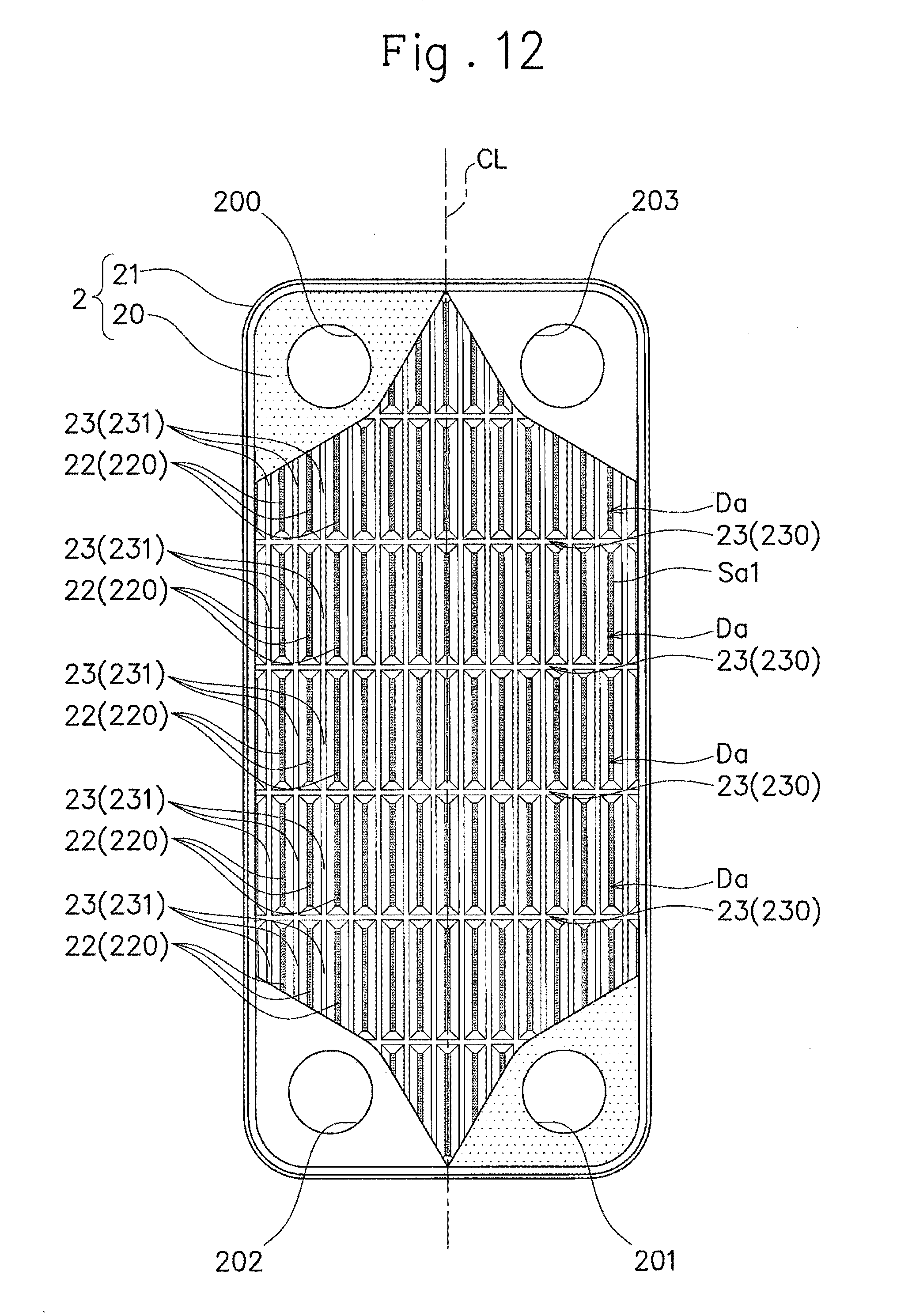
D00013
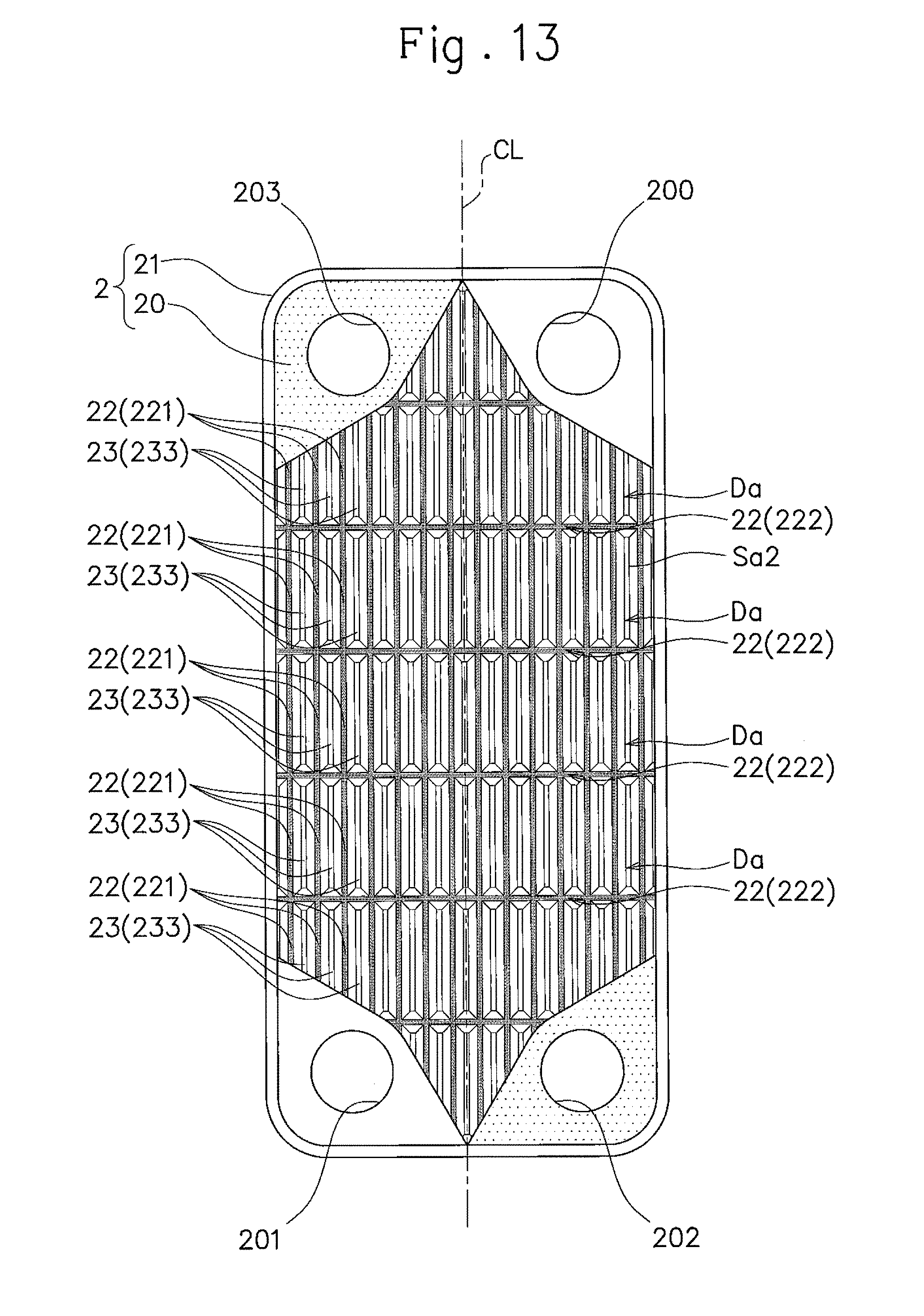
D00014
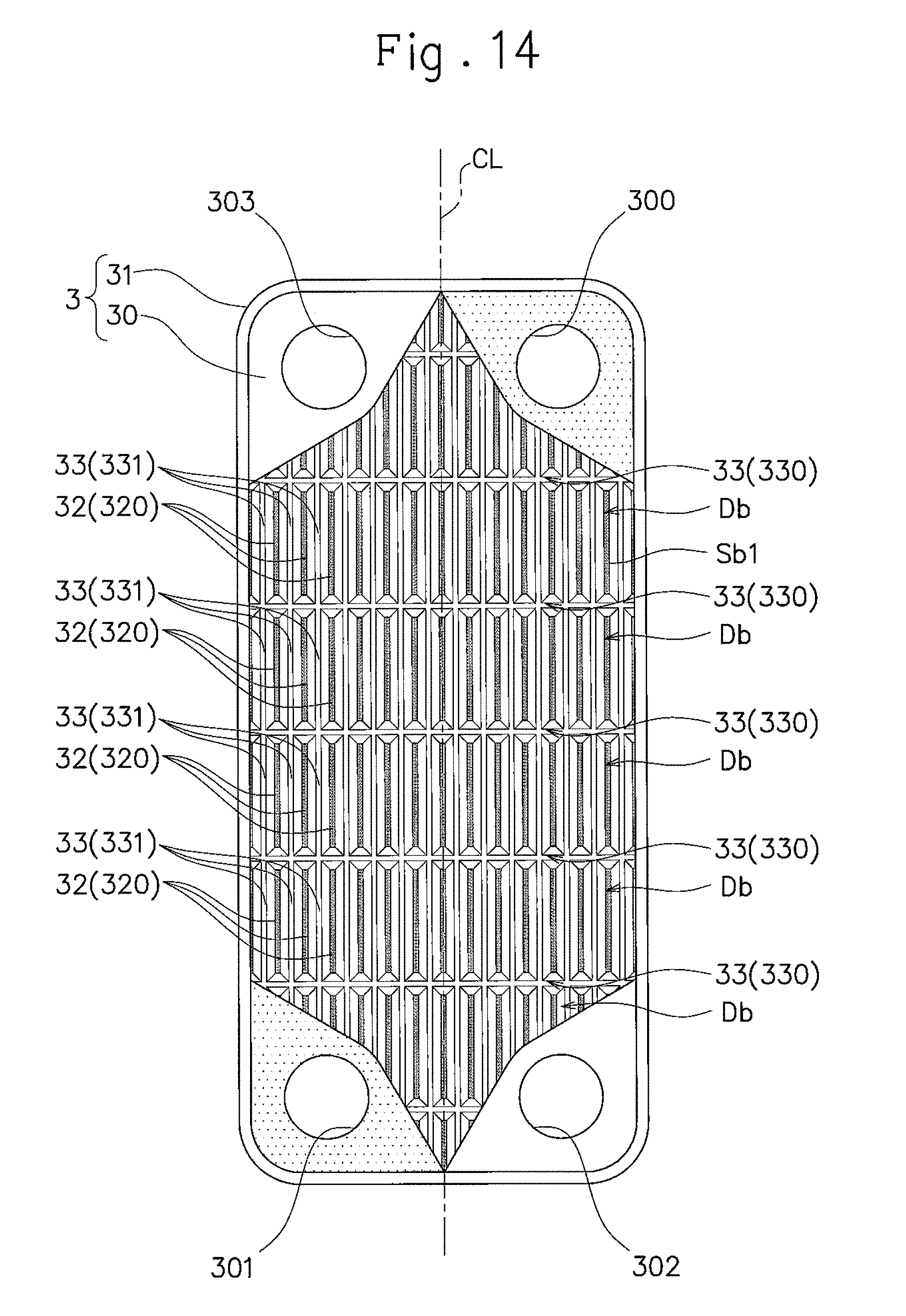
D00015
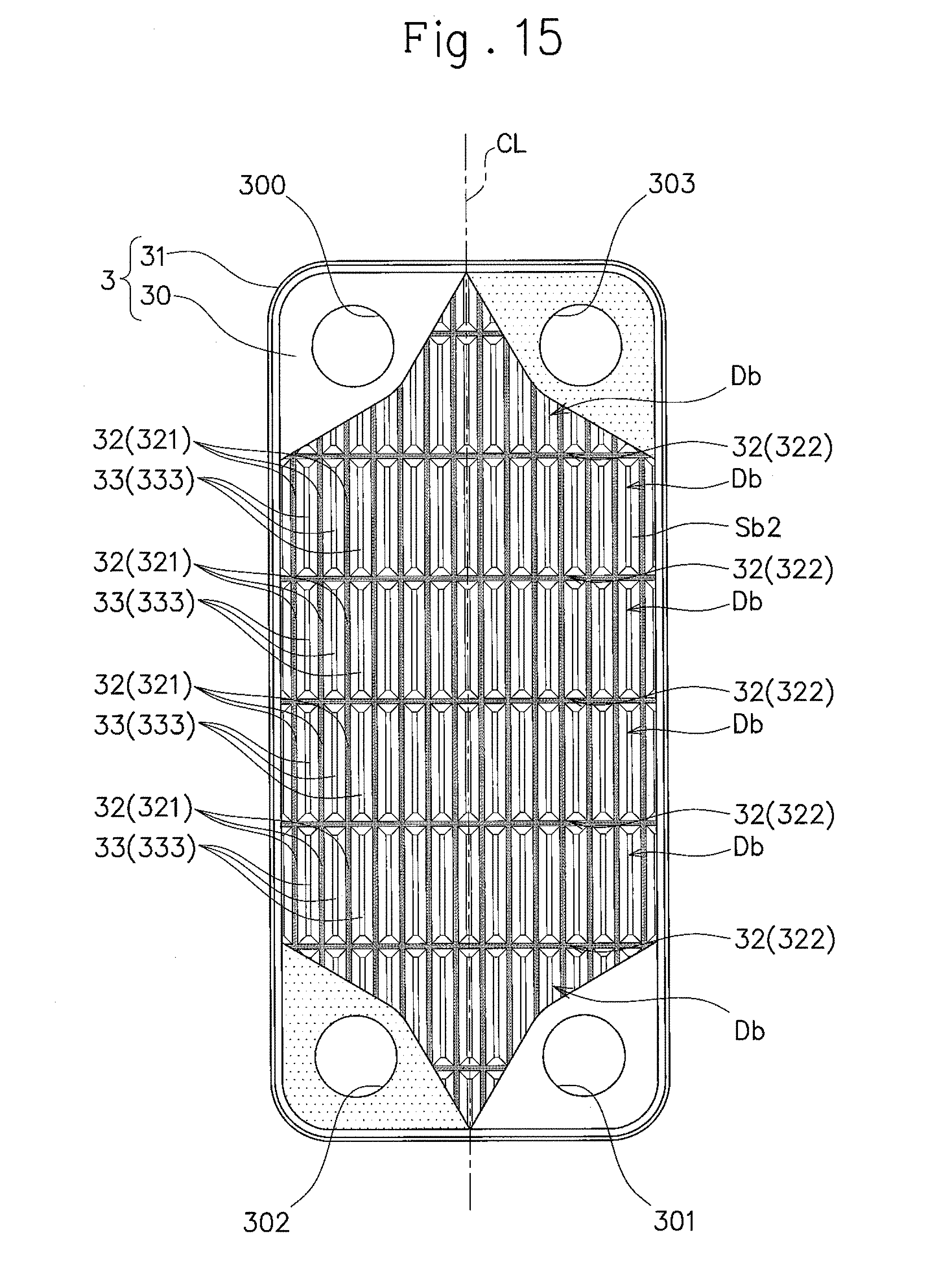
D00016
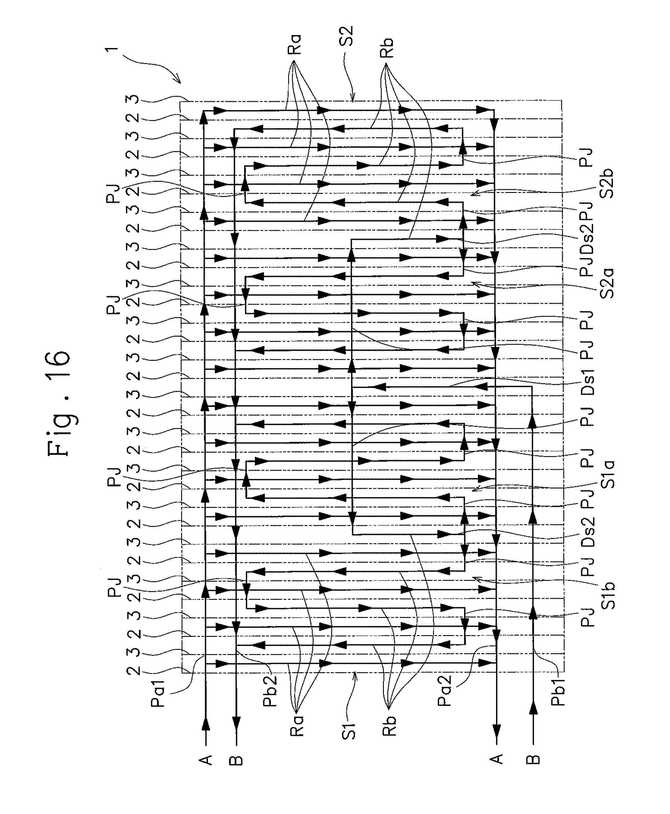
D00017
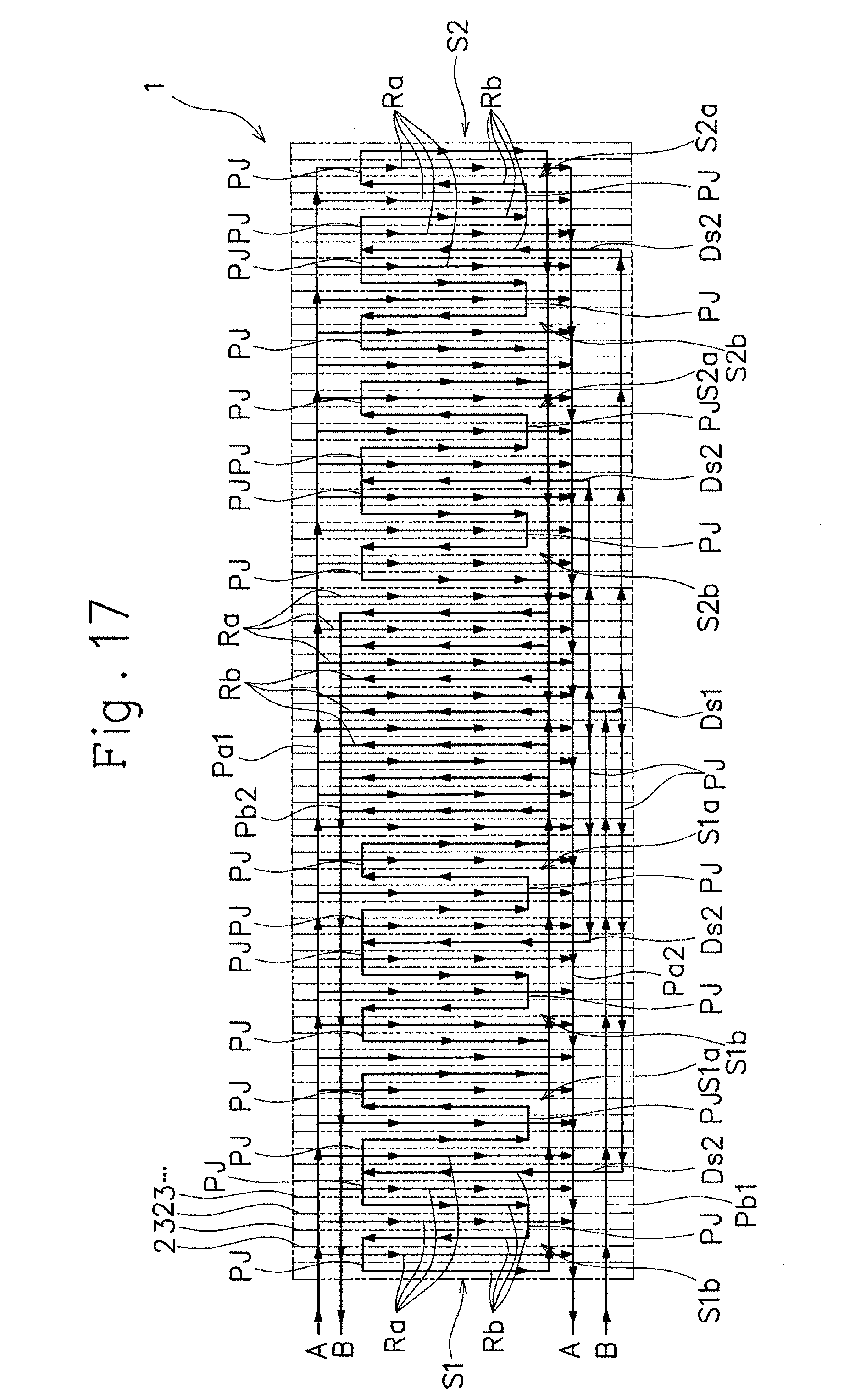
XML
uspto.report is an independent third-party trademark research tool that is not affiliated, endorsed, or sponsored by the United States Patent and Trademark Office (USPTO) or any other governmental organization. The information provided by uspto.report is based on publicly available data at the time of writing and is intended for informational purposes only.
While we strive to provide accurate and up-to-date information, we do not guarantee the accuracy, completeness, reliability, or suitability of the information displayed on this site. The use of this site is at your own risk. Any reliance you place on such information is therefore strictly at your own risk.
All official trademark data, including owner information, should be verified by visiting the official USPTO website at www.uspto.gov. This site is not intended to replace professional legal advice and should not be used as a substitute for consulting with a legal professional who is knowledgeable about trademark law.