Control Device To Achieve Variable Compression Ratio For Triangle Rotary Engine
FAN; Baowei ; et al.
U.S. patent application number 15/749461 was filed with the patent office on 2019-01-10 for control device to achieve variable compression ratio for triangle rotary engine. The applicant listed for this patent is Jiangsu University. Invention is credited to Wei CHEN, Baowei FAN, Yao LU, Jianfeng PAN.
| Application Number | 20190010806 15/749461 |
| Document ID | / |
| Family ID | 58819594 |
| Filed Date | 2019-01-10 |

| United States Patent Application | 20190010806 |
| Kind Code | A1 |
| FAN; Baowei ; et al. | January 10, 2019 |
CONTROL DEVICE TO ACHIEVE VARIABLE COMPRESSION RATIO FOR TRIANGLE ROTARY ENGINE
Abstract
The present invention provides an actuator that can realize the different compression ratios of the rotary engine. The invention actuator described above, includes three parts: the eccentric shaft part, the triangle rotor part and the control system. The eccentric shaft part which is described above, includes the front part of the eccentric shaft, the combination of electric three jaw and the rear part of the eccentric shaft. The triangle rotor part which is described above, includes the variable volume actuator, the front part of the rotor and the rear part of the rotor. The control system which is described above, includes the control system of electric three jaw and the rotating joint. The expansion and contraction of the electric three jaw described above, are controlled by the control system of electric three jaw described above. The eccentric shaft part described above passes through the triangle rotor part described above, to make the combination of electric three jaw to arrange in the annular groove described above. The reciprocating motion of the variable volume actuator described above, is controlled by the expansion and contraction of the claw top of the electric three-jaw. The invention can adjust the engine compression ratio through the whole compression ratio adjustment system, to make the rotary engine always work in the best compression ratio under different working conditions. Therefore, the invention can improve the performance of rotary engine significantly.
| Inventors: | FAN; Baowei; (Jiangsu, CN) ; PAN; Jianfeng; (Jiangsu, CN) ; LU; Yao; (Jiangsu, CN) ; CHEN; Wei; (Jiangsu, CN) | ||||||||||
| Applicant: |
|
||||||||||
|---|---|---|---|---|---|---|---|---|---|---|---|
| Family ID: | 58819594 | ||||||||||
| Appl. No.: | 15/749461 | ||||||||||
| Filed: | May 17, 2017 | ||||||||||
| PCT Filed: | May 17, 2017 | ||||||||||
| PCT NO: | PCT/CN2017/084642 | ||||||||||
| 371 Date: | January 31, 2018 |
| Current U.S. Class: | 1/1 |
| Current CPC Class: | F01C 20/20 20130101; Y02T 10/12 20130101; F01C 21/00 20130101; F01C 2021/1606 20130101; F01C 21/08 20130101; F01C 19/00 20130101; F01C 20/18 20130101; F02D 15/04 20130101; F01C 1/22 20130101; F02B 55/02 20130101; F02B 53/02 20130101 |
| International Class: | F01C 20/18 20060101 F01C020/18; F02D 15/04 20060101 F02D015/04; F02B 55/02 20060101 F02B055/02; F02B 53/02 20060101 F02B053/02; F01C 21/08 20060101 F01C021/08; F01C 19/00 20060101 F01C019/00 |
Foreign Application Data
| Date | Code | Application Number |
|---|---|---|
| Dec 6, 2016 | CN | 201611107050.5 |
Claims
1. (canceled)
2. The actuator of claim 6, which can achieve different compression ratios for rotary engine, wherein the surroundings of the variable volume plate, is arranged with the seal groove; The seal groove described above, is equipped with the wave spring; The sealing strip which is used as a seal between the variable volume plate and the rotor pocket, is installed on the outside of the wave spring.
3. The actuator of claim 6, which can achieve different compression ratios for rotary engine, wherein the shape of the rotor pocket described above, is a square groove.
4. The actuator of claim 6, which can achieve different compression ratios for rotary engine, wherein the angle of the two ends of the outer support arc block is chamfered outwards, so that the outer arc length of the section of outer support arc block is longer than the inner arc length of the section of outer support arc block.
5. The actuator of claim 6, which can achieve different compression ratios for rotary engine, wherein the angle of the two ends of the inner support arc block is chamfered inwards, so that the outer arc length of the section of inner support arc block is shorter than the inner arc length of the section of inner support arc block.
6. A actuator that can achieve different compression ratios for rotary engine, comprising: a eccentric shaft part; a triangle rotor part; and a control system; wherein the eccentric shaft part, includes the front part of the eccentric shaft, the combination of electric three-jaw and the rear part of the eccentric shaft; wherein the combination of electric three jaw which is described above, includes the end cap of the electric three-jaw and the electric three-jaw; wherein the telescopic distance of the claw top of the electric three-jaw is controlled by the electric three-jaw, by using the control system described above; wherein each claw top of the electric three-jaw which is described above, is fitted with the inner support arc block; wherein the front part of the eccentric shaft and the rear part of the eccentric shaft both have an eccentric circular table, respectively; wherein the front part of the eccentric shaft, is provided with the second through hole, which is internally fixed with a wire which is used to control the electric three-jaw; wherein the front part of the eccentric shaft, the combination of electric three-jaw and the rear part of the eccentric shaft, are fixedly connected through the second bolt; wherein the above connection ensures that the eccentric circular table of the front part of the eccentric shaft, is coaxial with the combination of electric three jaw and the eccentric circular table of the rear part of the eccentric shaft; wherein the triangle rotor part which is described above, includes the variable volume actuator, the front part of the rotor and the rear part of the rotor; wherein the outer surface of the front part of the rotor and the rear part of the rotor which are described above, is equipped with the rotor pocket; wherein the interior of the front part of the rotor and the rear part of the rotor, is equipped with the annular groove; wherein the first through hole is used to connect the rotor pocket and the annular groove which are described above; wherein the front part of the rotor and the rear part of the rotor, are fixedly connected through the first bolt to make the rotor pocket of the front part of the rotor align with the rotor pocket of the rear part of the rotor; wherein the variable volume actuator described above, is installed in the annular groove; wherein the variable volume actuator described above, comprises of the variable volume plate and the outer support arc block; wherein the connecting cylinder is used to connect variable volume plate and the outer support arc block; wherein one end of the extension spring is fixed on variable volume plate and the other end of the extension spring is fixed in the rotor pocket; wherein the outer support arc block is installed in the annular groove; wherein the control system which is described above, includes the control system of electric three-jaw and the rotating joint; wherein one end of the rotating joint described above, is connected with the wire in the second through hole; wherein the other end of the rotating joint is connected with the wire of the control system of electric three jaw; wherein the expansion and contraction of the electric three-jaw, is controlled by the control system of electric three-jaw; wherein the eccentric shaft part described above, passes through the triangle rotor part, to make the combination of electric three-jaw to arrange in the annular groove; wherein the reciprocating motion of the variable volume actuator described above, is controlled by the expansion and contraction of the claw top of the electric three-jaw.
Description
TECHNICAL FIELD
[0001] The invention relates to the technical field of a dynamic mechanical system. Especially, the invention relates to an actuator that can achieve different compression ratios for rotary engine (Wankel engine).
BACKGROUND ART
[0002] The compression ratio is the ratio of the total cylinder volume to the combustion chamber volume of an engine. It is an important parameter used to control combustion, detonation and emission of an engine. It is also an important parameter in the design field of the internal combustion engine. Generally speaking, the compression ratio of the traditional engine is not changeable. This is due to the fact that the design parameters of the total cylinder volume and combustion chamber volume are fixed and cannot be changed in the working process. It is known that increasing the compression ratio can improve the indicated thermal efficiency of the engine, improve the engine power, improve engine economy, improve engine emission performance, as well as improve the cold start performance of the engine. However, the oversized compression ratio will increase the engine's mechanical load, heat load and the possibility of detonation. In addition, the oversized compression ratio will also reduce the reliability and service life of the engine. Especially, when the turbocharger is used in the engine, the contradiction between the above two aspects is more prominent. This is mainly due to the fact that to prevent detonation, the compression ratio of the turbo-supercharged engine is lower than that of the naturally aspirated engine. In the actual operation of the turbo-supercharged engine, the turbocharging system begin to work only when the engine reaches a certain speed. This phenomenon is called "supercharging lag phenomenon". That is, under the condition of low engine speed, turbocharging system does not work. Therefore, compared with the natural aspirated engine, the torque rise of the turbo-supercharged engine is slow at low speed. This is mainly due to the fact that the compression ratio of turbocharged engine is lower than that of natural aspirated engine. However, under the condition of high engine speed, turbocharging system begin to work. With the increase of air intake, the volumetric efficiency is increased, giving a fast burning rate and thus high thermal efficiency and power output. This high combustion efficiency leads to the turbocharged engine cylinder more prone to detonation (also known as the "knock" phenomenon). In addition, the engine's mechanical load and heat load are increased, and the reliability of the engine is also very unfavorable. In order to solve the above contradiction of the compression ratio requirements on different working conditions (low engine speed and high engine speed), the invention has designed a variable compression ratio actuator for rotary engine, which can realize a continuous adjustment of the compression ratio for different working conditions. Therefore, the invention can ensure the best compression ratio from low engine speed to high engine speed in the whole operation range, which can overcome the defect of traditional rotary engine with an immutable compression ratio. From the above, the invention can improve the performance of rotary engine significantly.
CONTENTS OF THE INVENTION
[0003] In view of the defects in the existing technology, the invention provides a variable compression ratio actuator for rotary engine. According to the compression ratio requirements on the different working conditions, the invention can arbitrarily adjust the engine compression ratio to meet the above requirements. Therefore, the invention can make the rotary engine always work in the best compression ratio under different working conditions, and the performance of the rotary engine can be improved significantly.
[0004] To achieve the above technical purpose, the following technical means were used in the invention. The features of the invented actuator which can achieve different compression ratios for rotary engine, includes three parts: the eccentric shaft part, the triangle rotor part and the control system.
[0005] The eccentric shaft part which is described above, includes the front part of the eccentric shaft, the combination of electric three jaw and the rear part of the eccentric shaft. The combination of electric three jaw which is described above, includes the end cap of the electric three jaw and the electric three-jaw. The telescopic distance of the claw top of the electric three jaw which is described above, is controlled by the control system. Each claw top of the electric three jaw which is described above, is fitted with the inner support arc block. The front part of the eccentric shaft and the rear part of the eccentric shaft which are described above, both have an eccentric circular table, respectively. The front part of the eccentric shaft which is described above, is provided with the second through hole, which is internally fixed with a wire which is used to control the electric three-jaw. The front part of the eccentric shaft, the combination of electric three-jaw and the rear part of the eccentric shaft which are described above, are fixedly connected through the second bolt. In addition, the above connection must ensure that the eccentric circular table of the front part of the eccentric shaft, is coaxial with the combination of electric three-jaw and the eccentric circular table of the rear part of the eccentric shaft.
[0006] The triangle rotor part which is described above, includes the variable volume actuator, the front part of the rotor and the rear part of the rotor. The outer surface of the front part of the rotor and the rear part of the rotor which are described above, are equipped with the rotor pocket. The interior of the front part of the rotor and the rear part of the rotor which are described above, are equipped with the annular groove. The first through hole is used to connect the rotor pocket and the annular groove which are described above. The front part of the rotor and the rear part of the rotor which are described above, are fixedly connected through the first bolt to make the rotor pocket of the front part of the rotor align with the rotor pocket of the rear part of the rotor. The variable volume actuator described above, is installed in the annular groove described above. The variable volume actuator described above, comprises of the variable volume plate and the outer support arc block. The connecting cylinder is used to connect the variable volume plate and the outer support arc block which are described above. One end of the extension spring is fixed on the variable volume plate described above, and the other end of the extension spring is fixed in the rotor pocket described above. The outer support arc block described above, is installed in the annular groove described above.
[0007] The control system which is described above, includes the control system of electric three-jaw and the rotating joint. One end of the rotating joint described above, is connected with the wire in the second through hole. The other end of the rotating joint is connected with the wire of the control system of electric three-jaw.
[0008] The expansion and contraction of the electric three jaw described above, are controlled by the control system of electric three-jaw described above. The eccentric shaft part described above passes through the triangle rotor part described above, to make the combination of electric three-jaw to arrange in the annular groove described above. The reciprocating motion of the variable volume actuator described above, is controlled by the expansion and contraction of the claw top of the electric three-jaw.
[0009] Further, the variable volume plate described above, is arranged with the seal groove. The seal groove described above, is equipped with the wave spring. The sealing strip which is used as a seal between the variable volume plate and the rotor pocket, is installed on the outside of the wave spring.
[0010] Further, the shape of the rotor pocket described above, is a square groove.
[0011] Further, the angle of the two ends of the outer support arc block is chamfered outwards, so that the outer arc length of the section of outer support arc block is longer than the inner arc length of the section of outer support arc block.
[0012] Further, the angle of the two ends of the inner support arc block is chamfered inwards, so that the outer arc length of the section of inner support arc block is shorter than the inner arc length of the section of inner support arc block.
[0013] The advantages of the invention are as follows:
[0014] The actuator of the present invention which can achieve variable compression ratios for rotary engine, can be controlled by the control system, to provide the optimal compression ratio according to the compression ratio requirements on the different working conditions. Therefore, the invention can make the rotary engine always work in the best compression ratio under different working conditions, and the performance of the rotary engine can be improved significantly.
[0015] The actuator of the present invention which can achieve variable compression ratios for rotary engine, gives a new design for the rotor and the eccentric shaft of the traditional rotary engine. The new design realizes that the actuator can adjust the compression ratio for rotary engine, which can completely solve the existing defects of the existing traditional rotary engine which has a nonadjustable compression ratio.
DESCRIPTION OF DRAWINGS
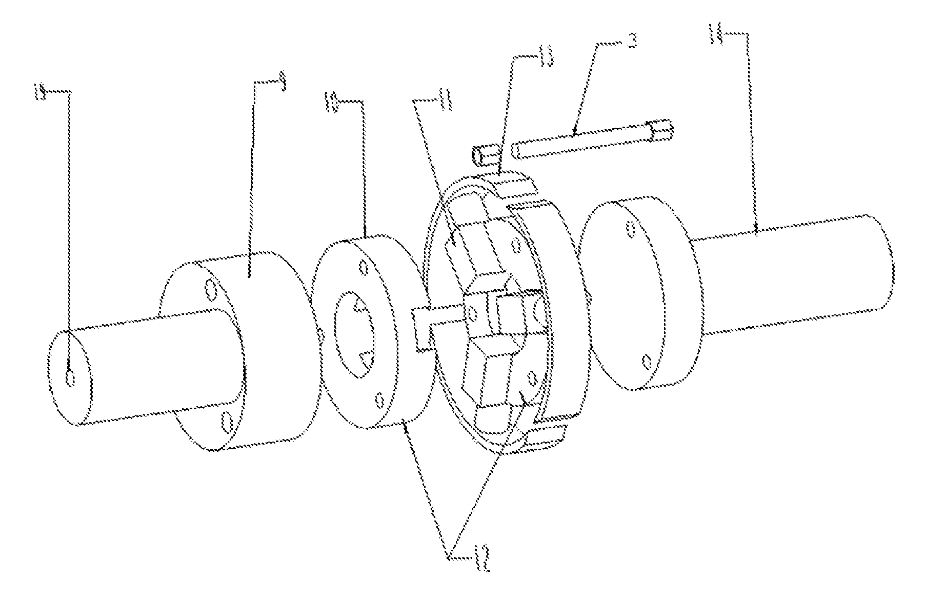
[0016] FIG. 1 is an assembly exploding diagram of the actuator which can realize different compression ratios of the rotary engine.
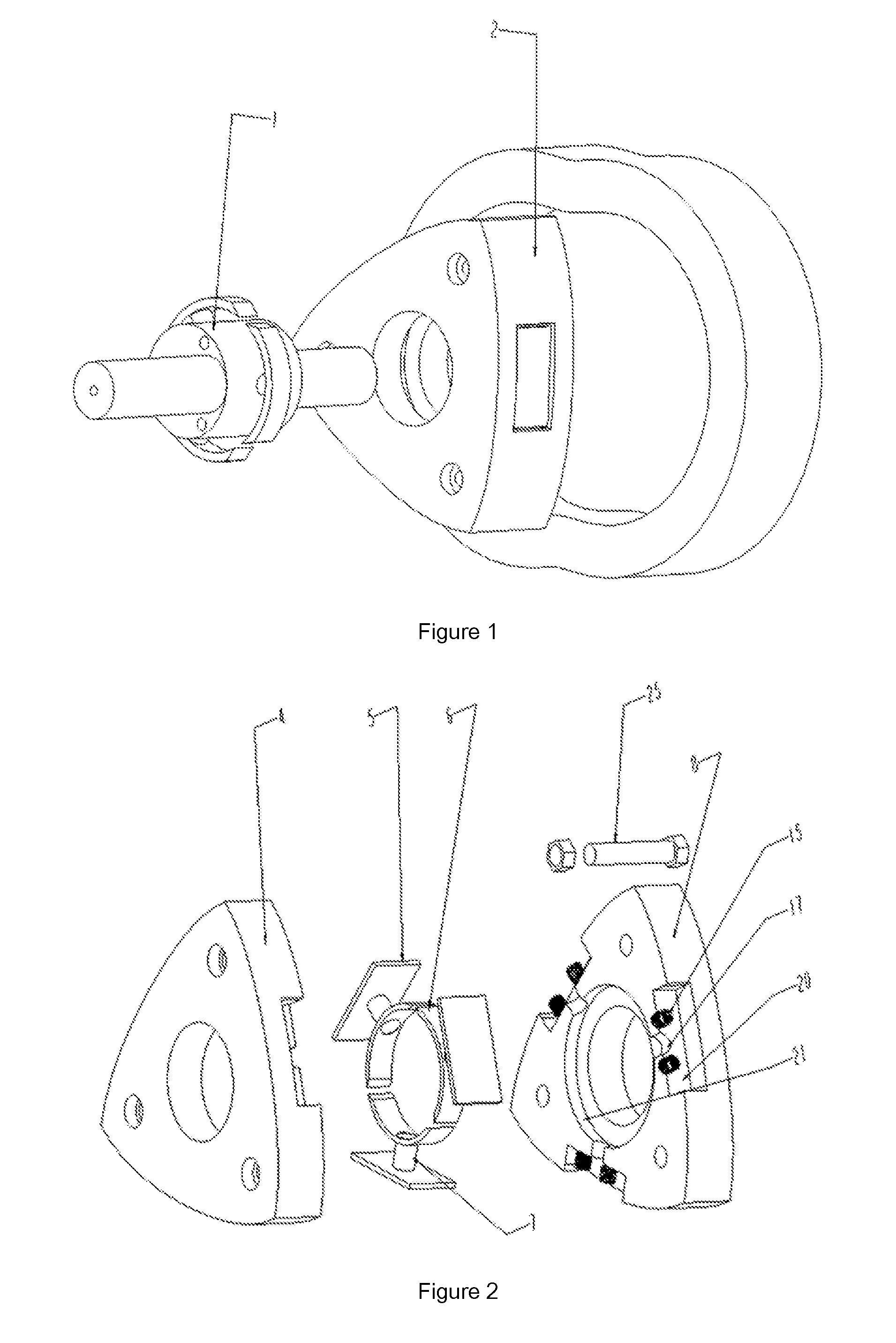
[0017] FIG. 2 is an assembly exploding diagram for the triangle rotor part described in the present invention.
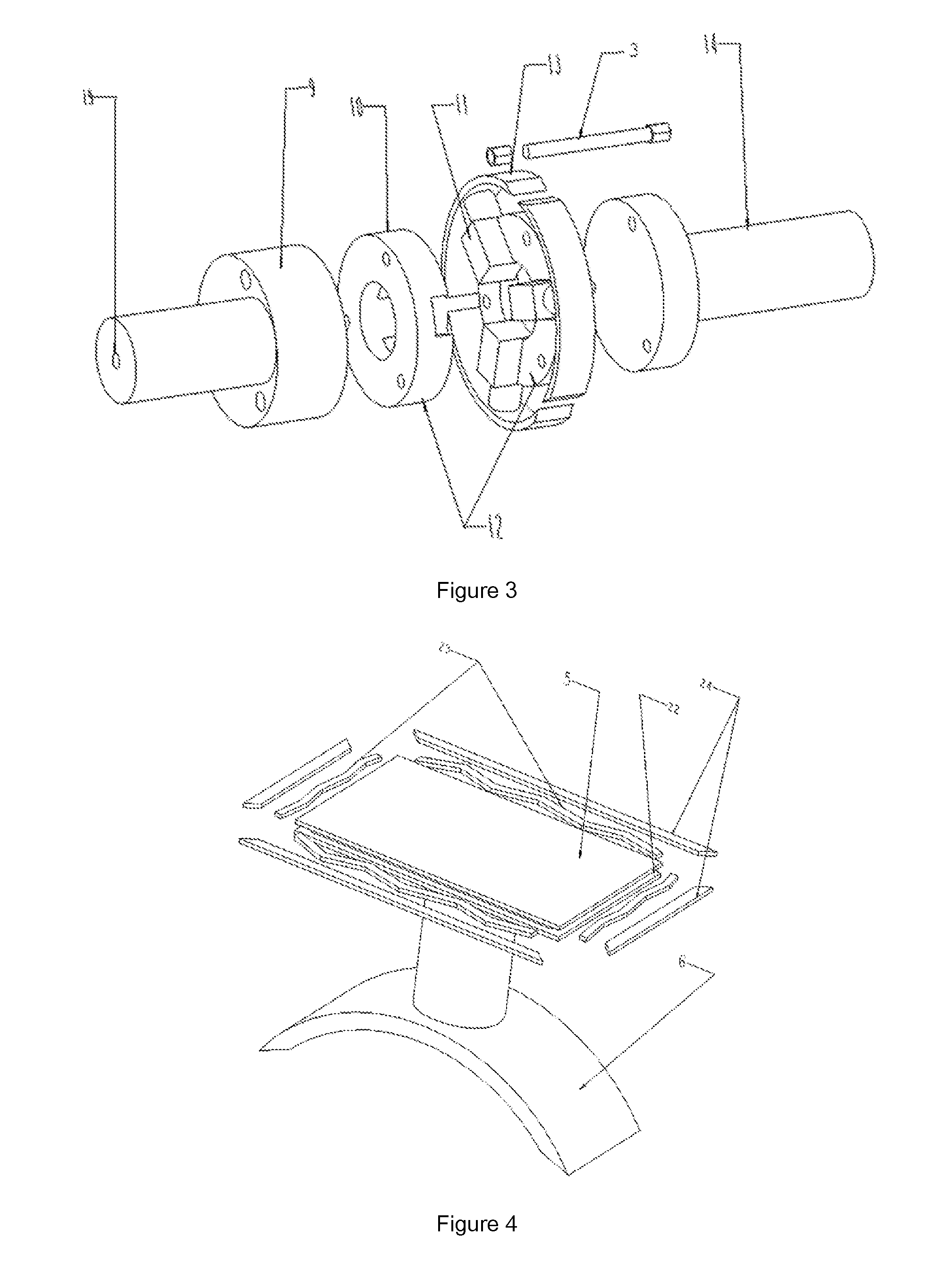
[0018] FIG. 3 is an assembly exploding diagram of the eccentric shaft part described in the present invention.
[0019] FIG. 4 is a schematic diagram of the principle of sealing on the variable volume plate.
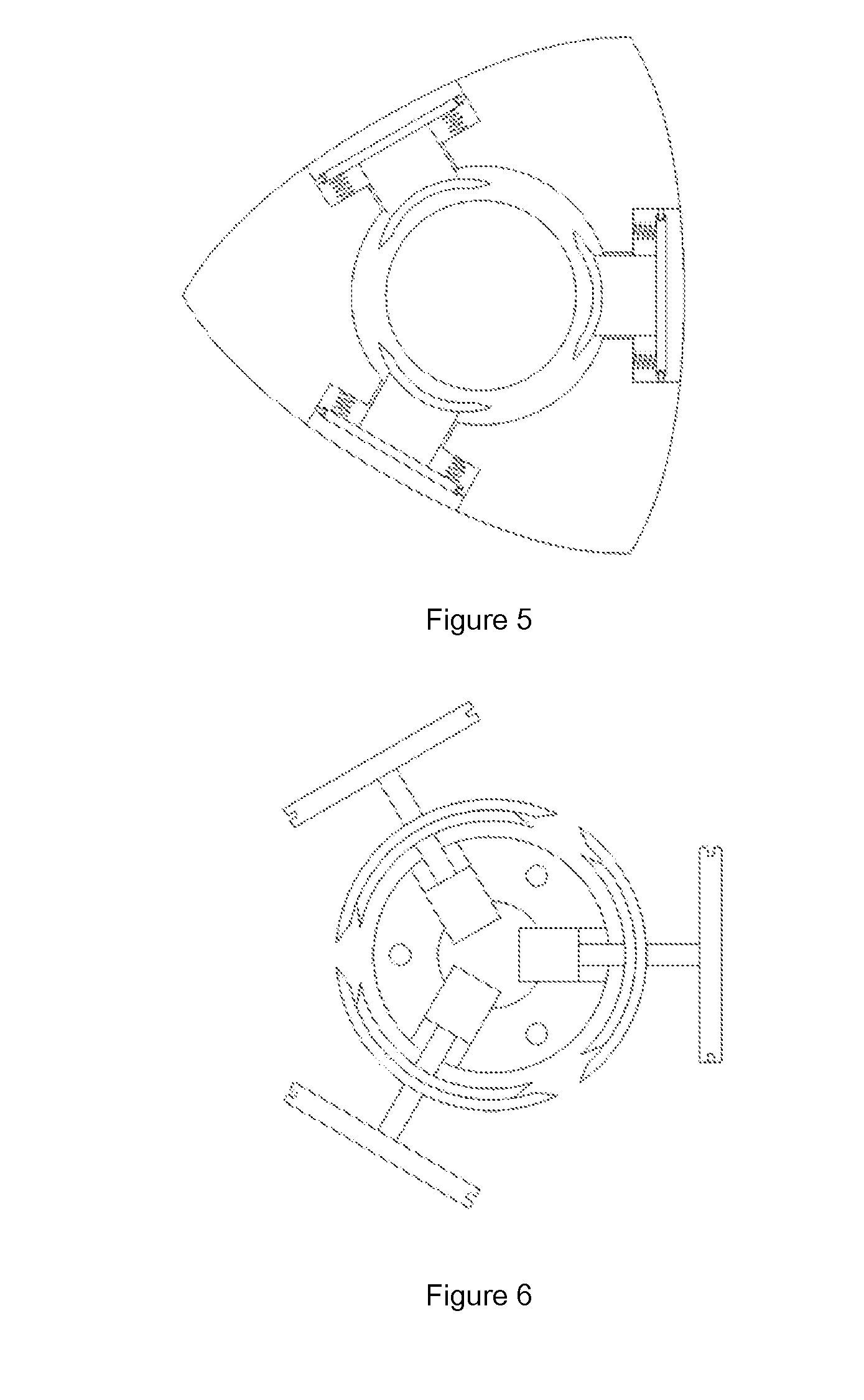
[0020] FIG. 5 is the layout of the variable volume actuator in the rotor.
[0021] FIG. 6 is a collaboration diagram of the variable volume actuator and the electric three jaw described in the present invention.
[0022] FIG. 7 is a schematic diagram of the control system described in the present invention.
[0023] In the figures: 1--the eccentric shaft part; 2--the triangle rotor part; 3--the second bolt; 4--the front part of the rotor; 5--the variable volume plate; 6--the outer support arc block; 7--the connecting cylinder; 8--the rear part of the rotor; 9--the front part of the eccentric shaft; 10--the end cap of the electric three-jaw; 11--electric three-jaw; 12--the combination of electric three-jaw; 13--the inner support arc block; 14--the rear part of the eccentric shaft; 15--the extension spring; 16--the rotating joint; 17--the first through hole; 18--the control system of electric three-jaw; 19--the second through hole; 20--the rotor pocket; 21--the annular groove; 22--the seal groove; 23--the wave spring; 24--the sealing strip; 25--the first bolt.
EMBODIMENTS
[0024] Hereunder the embodiments of the present invention will be described in detail with reference to the accompanying drawings.
[0025] Combining FIG. 1, FIG. 2, FIG. 3 and FIG. 7, the actuator which can achieve different compression ratios for rotary engine, includes three parts: the eccentric shaft part 1, the triangle rotor part 2 and the control system.
[0026] The eccentric shaft part 1 which is described above, includes the front part of the eccentric shaft 9, the combination of electric three jaw 12 and the rear part of the eccentric shaft 14. The combination of electric three jaw 12 which is described above, includes the end cap of the electric three-jaw 10 and the electric three-jaw 11. The telescopic distance of the claw top of the electric three jaw 11 is controlled by the electric three jaw 11, by using the control system described above. Each claw top of the electric three jaw 11 which is described above, is fitted with the inner support arc block 13. The front part of the eccentric shaft 9 and the rear part of the eccentric shaft 14 both have an eccentric circular table, respectively. The front part of the eccentric shaft 9, is provided with the second through hole 19, which is internally fixed with a wire which is used to control the electric three jaw 11. The front part of the eccentric shaft 9, the combination of electric three jaw 12 and the rear part of the eccentric shaft 14, are fixedly connected through the second bolt 3. In addition, the above connection ensures that the eccentric circular table of the front part of the eccentric shaft 9, is coaxial with the combination of electric three-jaw 12 and the eccentric circular table of the rear part of the eccentric shaft 14.
[0027] The triangle rotor part 2 which is described above, includes the variable volume actuator, the front part of the rotor 4 and the rear part of the rotor 8. The outer surface of the front part of the rotor 4 and the rear part of the rotor 8 which are described above, is equipped with the rotor pocket 20. The interior of the front part of the rotor 4 and the rear part of the rotor 8, is equipped with the annular groove 21. The first through hole 17 is used to connect the rotor pocket 20 and the annular groove 21 which are described above. The shape of the rotor pocket 20, is a square groove. The front part of the rotor 4 and the rear part of the rotor 8, are fixedly connected through the first bolt 25 to make the rotor pocket 20 of the front part of the rotor 4 align with the rotor pocket 20 of the rear part of the rotor 8. The variable volume actuator described above, is installed in the annular groove 21. The variable volume actuator described above, comprises of the variable volume plate 5 and the outer support arc block 6. The connecting cylinder 7 is used to connect variable volume plate 5 and the outer support arc block 6. One end of the extension spring 15 is fixed on variable volume plate 5, and the other end of the extension spring 15 is fixed in the rotor pocket 20. The outer support arc block 6, is installed in the annular groove 21.
[0028] The control system which is described above, includes the control system of electric three jaw 18 and the rotating joint 16. One end of the rotating joint 16 described above, is connected with the wire in the second through hole 19. The other end of the rotating joint 16 is connected with the wire of the control system of electric three jaw 18. The expansion and contraction of the electric three jaw 11, are controlled by the control system of electric three-jaw 18.
[0029] The eccentric shaft part 1 described above, passes through the triangle rotor part 2, to make the combination of electric three-jaw 12 to arrange in the annular groove 21. The reciprocating motion of the variable volume actuator described above, is controlled by the expansion and contraction of the claw top of the electric three-jaw 11.
[0030] As the wire in the second through hole 19 connects to the electric three-jaw 11, the wire in the second through hole 19 and the eccentric shaft part 1, do rotational motion together in the actual working process of the rotary engine. Therefore, the wire in the second through hole 19 uses hard wire. In addition, the wire in the second through hole 19 is linked to the control system of electric three-jaw 18, by using the rotating joint 16. The above method can prevent the torsion of the wire in the second through hole 19, which protects the normal operation of the control system of electric three jaw 18.
[0031] The specific work process is as follows:
[0032] According to the compression ratio requirements on the different working conditions, the expansion and contraction of the electric three jaw 11 are controlled by the control system of electric three jaw 18. When the compression ratio needs to be increased, the electric three jaw 11 is extended. The motion of the variable volume actuator is driven by the inner support arc block 13, to reduce the volume of the rotor pocket 20 which is used as a part of combustion chamber. When the compression ratio needs to be decreased, the electric three jaw 11 is contracted. At the same time, the variable volume actuator is pulled back by the extension spring 15 which is fixed in the rotor pocket 20, to increase the volume of the rotor pocket 20 which is used as a part of combustion chamber.
[0033] As there is a reciprocating motion of the variable volume plate 5 in the rotor pocket 20, there is a need to take measures to ensure the seal between the variable volume plate 5 and the rotor pocket 20. The surroundings of the variable volume plate 5, as shown in FIG. 4 and FIG. 5 is arranged in the seal groove 22. The seal groove 22 described above, is equipped with the wave spring 23. The sealing strip 24 which is used as a seal between the variable volume plate 5 and the rotor pocket 20, is installed on the outside of the wave spring 23.
[0034] As shown in FIG. 6, in the working process of the rotary engine, the rotational speed of the eccentric shaft and the rotational speed of the rotor are different. Therefore, although the inner support arc block 13 and the outer support arc block 6 are always stuck together, there is a relative rotation motion. In order to prevent the movement interferences between the inner support arc block 13 and the outer support arc block 6, the angle of the two ends of the outer support arc block 6 is chamfered outwards, so that the outer arc length of the section of outer support arc block 6 is longer than the inner arc length of the section of outer support arc block 6. In addition, the angle of the two ends of the inner support arc block 13 is chamfered inwards, so that the outer arc length of the section of inner support arc block 13 is shorter than the inner arc length of the section of inner support arc block 13.
[0035] The embodiments of the invention described above, is the preferred implementation method. However, the invention is not restricted to the embodiments of the invention described above. Without deviating from the essential content of the invention, any visible improvement, replacement or modification made by the technical staff in the field, is all within the scope of protection of the invention.
* * * * *
D00000
D00001
D00002
D00003
D00004
XML
uspto.report is an independent third-party trademark research tool that is not affiliated, endorsed, or sponsored by the United States Patent and Trademark Office (USPTO) or any other governmental organization. The information provided by uspto.report is based on publicly available data at the time of writing and is intended for informational purposes only.
While we strive to provide accurate and up-to-date information, we do not guarantee the accuracy, completeness, reliability, or suitability of the information displayed on this site. The use of this site is at your own risk. Any reliance you place on such information is therefore strictly at your own risk.
All official trademark data, including owner information, should be verified by visiting the official USPTO website at www.uspto.gov. This site is not intended to replace professional legal advice and should not be used as a substitute for consulting with a legal professional who is knowledgeable about trademark law.