High Hardness Wear-resistant Steel With Excellent Toughness And Cutting Crack Resistance And Method For Manufacturing Same
YI; Il-Cheol ; et al.
U.S. patent application number 16/062566 was filed with the patent office on 2019-01-10 for high hardness wear-resistant steel with excellent toughness and cutting crack resistance and method for manufacturing same. The applicant listed for this patent is POSCO. Invention is credited to Sang-Deok KANG, Sung-Kyu KIM, Yong-Jin KIM, Un-Hae LEE, Il-Cheol YI.
| Application Number | 20190010571 16/062566 |
| Document ID | / |
| Family ID | 59052836 |
| Filed Date | 2019-01-10 |
| United States Patent Application | 20190010571 |
| Kind Code | A1 |
| YI; Il-Cheol ; et al. | January 10, 2019 |
HIGH HARDNESS WEAR-RESISTANT STEEL WITH EXCELLENT TOUGHNESS AND CUTTING CRACK RESISTANCE AND METHOD FOR MANUFACTURING SAME
Abstract
The present invention relates to a high hardness wear-resistant steel with excellent toughness and cutting crack resistance, and a method for manufacturing the same. A high hardness wear-resistant steel according to one aspect of the present invention has a composition containing, by weight ratio, 2.1 to 4.0% of manganese (Mn), 0.15 to 0.2% of carbon (C), 0.02 to 0.5% of silicon (Si), 0.2 to 0.7% of chromium (Cr), a remainder of iron (Fe) and other unavoidable impurities, has a microstructure in which prior austenite grain size is 25 .mu.m or less and martensite is included as a main phase, and has excellent toughness and cutting crack resistance which satisfies a condition in which Ac3-Ac1 is 100.degree. C. or lower.
| Inventors: | YI; Il-Cheol; (Gwangyang-si, Jeollanam-do, KR) ; KIM; Yong-Jin; (Gwangyang-si, Jeollanam-do, KR) ; KIM; Sung-Kyu; (Gwangyang-si, Jeollanam-do, KR) ; KANG; Sang-Deok; (Gwangyang-si, Jeollanam-do, KR) ; LEE; Un-Hae; (Gwangyang-si, Jeollanam-do, KR) | ||||||||||
| Applicant: |
|
||||||||||
|---|---|---|---|---|---|---|---|---|---|---|---|
| Family ID: | 59052836 | ||||||||||
| Appl. No.: | 16/062566 | ||||||||||
| Filed: | November 22, 2016 | ||||||||||
| PCT Filed: | November 22, 2016 | ||||||||||
| PCT NO: | PCT/KR2016/013491 | ||||||||||
| 371 Date: | June 14, 2018 |
| Current U.S. Class: | 1/1 |
| Current CPC Class: | C21D 6/008 20130101; C21D 6/002 20130101; C21D 8/0263 20130101; C22C 38/28 20130101; C22C 38/26 20130101; C21D 2211/001 20130101; C21D 1/18 20130101; C21D 6/005 20130101; C22C 38/38 20130101; C21D 8/0205 20130101; C22C 38/32 20130101; C21D 9/46 20130101; C22C 38/02 20130101; C21D 8/02 20130101; C21D 2211/008 20130101 |
| International Class: | C21D 9/46 20060101 C21D009/46; C22C 38/38 20060101 C22C038/38; C22C 38/32 20060101 C22C038/32; C22C 38/28 20060101 C22C038/28; C22C 38/26 20060101 C22C038/26; C22C 38/02 20060101 C22C038/02; C21D 8/02 20060101 C21D008/02; C21D 6/00 20060101 C21D006/00; C21D 1/18 20060101 C21D001/18 |
Foreign Application Data
| Date | Code | Application Number |
|---|---|---|
| Dec 15, 2015 | KR | 10-2015-0179009 |
Claims
1. A high hardness wear-resistant steel: having a composition containing, by weight ratio, 2.1 to 4.0% of manganese (Mn), 0.15 to 0.2% of carbon (C), 0.02 to 0.5% of silicon (Si), 0.2 to 0.7% of chromium (Cr), a remainder of iron (Fe) and other unavoidable impurities; having a microstructure in which prior austenite grain size is 25 .mu.m or less and martensite is included as a main phase; and having excellent toughness and cutting crack resistance which satisfies a condition in which Ac3-Ac1 is 100.degree. C. or lower.
2. The high hardness wear-resistant steel according to claim 1, further comprising, by weight ratio, 0.1% or less of niobium (Nb), 0.02% or less of boron (B), and 0.1% or less of titanium (Ti).
3. The high hardness wear-resistant steel according to claim 1, wherein the structure of martensite comprises 95% or more in area fraction.
4. The high hardness wear-resistant steel according to claim 1, wherein Brinell hardness is 420 to 480, and Charpy impact energy is 35 J or more at -40.degree. C.
5. The high hardness wear-resistant steel according to claim 1, wherein the martensite does not contain carbides therein.
6. A method of manufacturing a high hardness wear-resistant steel having excellent toughness and cutting crack resistance, comprising: hot-rolling a slab having a composition containing, by weight ratio, 2.1 to 4.0% of manganese (Mn), 0.15 to 0.2% of carbon (C), 0.02 to 0.5% of silicon (Si), 0.2 to 0.7% of chromium (Cr), a remainder of iron (Fe) and other unavoidable impurities, to provide a steel plate, quenching the steel plate to a temperature of 200.degree. C. or lower at a cooling rate of 3.degree. C./sec or higher, reheating the quenched steel plate to an austenite temperature range, and secondarily quenching the reheated steel plate to a temperature of 200.degree. C. or lower at a cooling rate of 3.degree. C./sec or higher.
7. The method according to claim 6, wherein the high hardness wear-resistant steel further comprising, by weight ratio, 0.1% or less of niobium (Nb), 0.02% or less of boron (B), and 0.1% or less of titanium (Ti).
8. The method according to claim 6, wherein an finishing temperature of the hot-rolling is an Ar3 or higher.
9. The method according to claim 6, wherein a heating temperature in the reheating operation is in the range of an Ar3 to 960.degree. C.
10. The method according to claim 6, wherein an austenite grain size of the steel plate to be secondarily quenched is 25 .mu.m or less.
11. The high hardness wear-resistant steel according to claim 2, wherein the structure of martensite comprises 95% or more in area fraction.
12. The high hardness wear-resistant steel according to claim 2, wherein Brinell hardness is 420 to 480, and Charpy impact energy is 35 J or more at -40.degree. C.
13. The high hardness wear-resistant steel according to claim 2, wherein the martensite does not contain carbides therein
14. The method according to claim 7, wherein an finishing temperature of the hot-rolling is an Ar3 or higher.
15. The method according to claim 7, wherein a heating temperature in the reheating operation is in the range of an Ar3 to 960.degree. C.
16. The method according to claim 7, wherein an austenite grain size of the steel plate to be secondarily quenched is 25 .mu.m or less.
Description
TECHNICAL FIELD
[0001] The present invention relates to a high hardness wear-resistant steel with excellent toughness and cutting crack resistance, and a method for manufacturing the same. The present invention claims benefit of priority to Korean Patent Application No. 10-2015-0179009, the disclosure of which is incorporated herein by reference in its entirety.
BACKGROUND ART
[0002] In fields of the production of industrial equipment such as dump trucks for mines, heavy construction equipment, construction equipment, and the like, there may be a high demand for wear-resistant steels having a hardness of 450 or higher on the basis of Brinell hardness.
[0003] Wear-resistant steels have to have a high surface hardness. High hardness martensitic steels have high hardness as well as high yield strength and tensile strength to be widely used for structural materials, transportation/construction machines, and the like.
[0004] Generally, a steel composition contains a large amount of alloying elements and high carbon to secure so-called quenchability, and a quenching operation in a manufacturing process may be essentially included, to produce high hardness martensitic steels.
[0005] However, since conventional martensitic steels may contain large amounts of carbon and alloying elements therein, the weldability and low-temperature toughness of such steels may be adversely affected, and such steels may also have a poor resistance to cracks generated in the cut portion when cutting steel to a desired size, i.e. poor cutting crack resistance.
DISCLOSURE
Technical Problem
[0006] An aspect of the present invention may provide a high hardness wear-resistant steel having high toughness and cutting crack resistance while relatively reducing the addition amount of alloying elements, such as carbon (C), or the like, which may adversely affect toughness, or the like of the wear-resistant steel.
[0007] Another aspect of the present invention may provide a manufacturing method for efficiently producing the above-mentioned high-hardness wear-resistant steel.
[0008] An object of the present invention may be not limited to the above description. It will be apparent to those skilled in the art that the present invention may be practiced other than is specifically described herein.
Technical Solution
[0009] According to an aspect of the present invention, a high hardness wear-resistant steel has a composition containing, by weight ratio, 2.1 to 4.0% of manganese (Mn), 0.15 to 0.2% of carbon (C), 0.02 to 0.5% of silicon (Si), 0.2 to 0.7% of chromium (Cr), a remainder of Fe and other unavoidable impurities, has a microstructure in which prior austenite grain size is 25 .mu.m or less and martensite is included as a main phase, and satisfies a condition in which Ac3-Ac1 is 100.degree. C. or lower.
[0010] According to an aspect of the present invention, a method of manufacturing a high hardness wear-resistant steel, includes: hot-rolling a slab having a composition containing, by weight ratio, 2.1 to 4.0% of manganese (Mn), 0.15 to 0.2% of carbon (C), 0.02 to 0.5% of silicon (Si), 0.2 to 0.7% of chromium (Cr), a remainder of Fe and other unavoidable impurities, to provide a steel plate, quenching the steel plate to a temperature of 200.degree. C. or lower at a cooling rate of 3.degree. C./sec or higher, reheating the quenched steel plate to an austenite temperature range, and secondarily quenching the reheated steel plate to a temperature of 200.degree. C. or lower at a cooling rate of 3.degree. C./sec or higher.
Advantageous Effects
[0011] According to an aspect of the present invention, the present invention may provide steel having high toughness and high cutting crack resistance while maintaining hardness of the steel at a 450 HB level, by increasing an amount of manganese (Mn) and conducting ultra-refinement of grains, instead of optimizing an amount of carbon (C) in the steel.
[0012] Effects of the present invention are not limited to those described above, and additional effects of the present invention will be fully understood from the following detailed description.
DESCRIPTION OF DRAWINGS
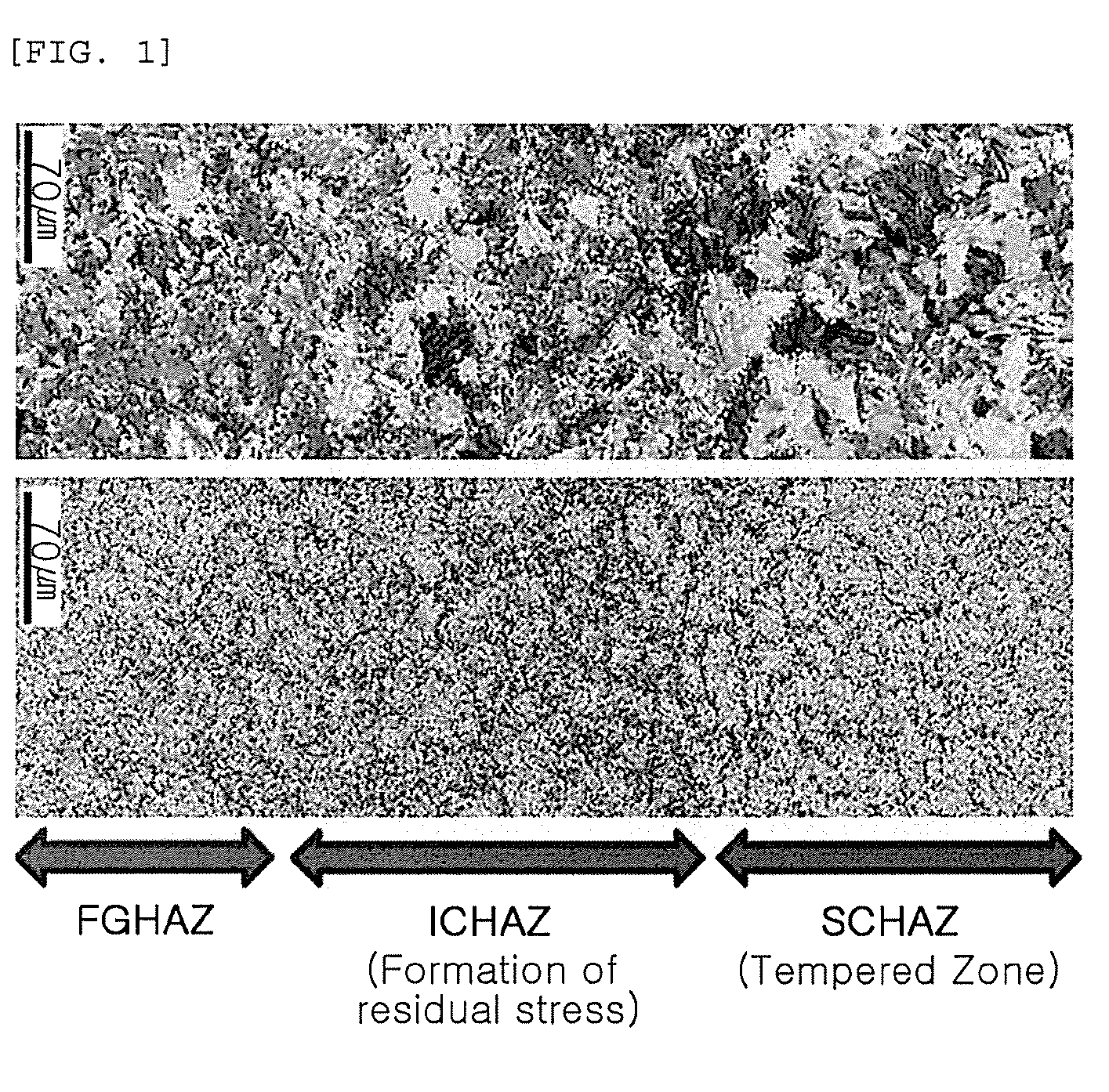
[0013] FIG. 1 is a view illustrating results of EBSD (Electron Back Scatter Diffraction) analysis of a heat affected zone formed in gas cutting, and
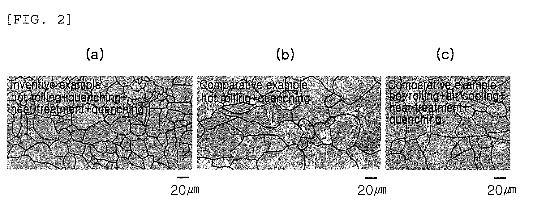
[0014] FIG. 2 is microscopy images illustrating structures of Inventive Example 1, Comparative Example 1 and Comparative Example 2 obtained from Example 1.
BEST MODE FOR INVENTION
[0015] Hereinafter, the present invention will be described in detail.
[0016] In the present invention, an amount of carbon (C) in steel may be adjusted to be within an appropriate range to ensure a low-temperature toughness of a wear-resistant steel, and a large amount of manganese (Mn) may be added to secure quenchability. Further, alloying components may be appropriately controlled to secure cutting crack resistance. Hereinafter, a composition of the present invention will be described.
[0017] A wear-resistant steel according to the present invention may have a composition, by weight ratio, containing 2.1 to 4.0% of manganese (Mn), 0.15 to 0.2% of carbon (C), 0.02 to 0.5% of silicon (Si), 0.2 to 0.7% of chromium (Cr), a remainder of iron (Fe) and other unavoidable impurities. It should be noted that amounts of each component in the present invention may be expressed on the basis of weight unless otherwise specified.
[0018] Manganese (Mn): 2.1 to 4.0%
[0019] Manganese (Mn) may be an element added to stabilize martensite and obtain high surface hardness. In the present invention, manganese (Mn) may be added in an amount of 2.1% or more to obtain this effect. When an amount of manganese (Mn) is insufficient, ferrite or bainite may be easily produced, and high hardness of a surface layer may thus be difficult to obtain. When an amount of manganese (Mn) exceeds 4.0%, not only weldability and cutting crack resistance may be remarkably reduced, but manufacturing costs of the steel may also be significantly reduced. Therefore, in the present invention, an amount of manganese (Mn) may be added in the range of 2.1 to 4.0%.
[0020] Carbon (C): 0.15 to 0.2%
[0021] Carbon (C) may be an element added to secure hardness of a surface layer in the steel, similar to manganese (Mn). However, when an amount thereof is excessively high, there may be a problem in which toughness and weldability are significantly lowered, such that the amount is required to be controlled within an appropriate range. In the present invention, 0.15% or more of carbon (C) may be added to ensure sufficient hardness of a surface layer. However, the upper limit of the amount may be 0.20% since toughness and weldability may be deteriorated when Mn is added in an excessively high amount.
[0022] Silicon (Si): 0.02-0.5%
[0023] Silicon (Si) may be an element added to serve as a deoxidizing agent, and may improve strength by solid solution strengthening. In addition, since the amount may not be reduced to a very small amount at the time of production, a lower limit of an amount of Silicon (Si) may be set to be 0.02%. When the amount is excessively high, toughness of a base material as well as that of a welded portion may be significantly reduced, such that the amount may be limited to 0.5% or less.
[0024] Chromium (Cr): 0.2 to 0.7%
[0025] When chromium (Cr) is included in steel, it may serve a role in raising the hardenability of the steel to facilitate securing martensite when quenching. Further, in the wear-resistant steel of the present invention, as the amount thereof increases, impact toughness at low temperature may be improved, and an interval between an Ac1 and an Ac3, phase transformation temperatures, may be narrowed to improve cutting cracking resistance. The amount thereof may be advantageously 0.2% or more to obtain such an advantageous effect of chromium (Cr). When the amount is excessively high, there may be a risk of lowering the weldability and raising the manufacturing cost, such that upper limit of the amount of chromium (Cr) may be set to be 0.7%.
[0026] In addition, the wear-resistant steel of the present invention may further contain 0.1% or less of niobium (Nb), 0.02% or less of boron (B), and 0.1% or less of titanium (Ti), in addition to the above-described alloying elements.
[0027] Niobium (Nb): 0.1% or Less
[0028] Niobium (Nb) may be an element increasing the strength of steel by effects of solid solution strengthening, precipitation hardening, or the like, and improves impact toughness by conducting grain refinement, and may be added as needed. When the amount is excessively high, coarse precipitates may be formed to deteriorate hardness and impact toughness, such that the amount thereof may be limited to 1.0% or less.
[0029] Boron (B): 0.02% or Less
[0030] Boron (B) may be an element that effectively increases quenchability of a material even with a small amount of addition, and has an effect of inhibiting grain boundary fractures by strengthening grain boundaries, and may be added and used as needed. When the amount thereof is excessively high, toughness and weldability may be significantly lowered due to formation of coarse precipitates, or the like. Therefore, the amount thereof may preferably be limited to 0.02% or less.
[0031] Titanium (Ti): 0.1% or Less
[0032] Nitrogen (N) may be mentioned as an impurity element which may be inevitably included in steel. When nitrogen (N) is combined with boron (B), there may be an adverse effect of decreasing the effect of boron (B). Titanium (Ti) may be an element which is effective in suppressing the decrease of the effect of boron (B) by nitrogen (N), and significantly increasing the addition effect of boron (B). For example, titanium (Ti) may react with nitrogen (N) present in steel to form TiN, thereby suppressing formation of BN. In addition, TiN may also have the effects of pinning austenite grains, and suppressing coarsening of the grains. Therefore, in the present invention, titanium (Ti) may be added in the steel as required. When the addition amount of titanium (Ti) may be excessively high, coarse precipitates may be formed to lower toughness and weldability, such that the amount thereof may be limited to 0.1% or less.
[0033] One of remainder components of the present invention may be iron (Fe). Since impurities, which are not intended, may be inevitably incorporated from raw material or surrounding environment in the conventional steel manufacturing process, the wear-resistant steel of the present invention does not specifically exclude the impurities. The kinds and amounts of these impurities are not particularly limited in the present invention, since they may be known to any one of ordinary skill in the art.
[0034] The wear-resistant steel of the present invention may have a value of Ac3-Ac1 of 100.degree. C. or lower, in addition to the above-mentioned composition system, to improve cutting crack resistance. According to the research results of the inventors of the present invention, the cutting crack generated at the time of gas cutting may be a kind of hydrogen induced crack, and may be characterized by the fact that it is more likely to occur as residual stress generated in a heat affected zone (in particular, ICHAZ) is relatively high. Therefore, reducing the residual stress of the heat affected zone may be one means of improving crack resistance. In the present invention, it may be proposed to adjust the value of Ac3-Ac1 for this purpose. For example, an Ac3 is a temperature at which pro-eutectoid ferrite begins to be generated in austenite during cooling, and an Ac1 is a temperature at which a structure is entirely transformed into ferrite. According to the results of research conducted by the present inventors, when controlling the value of Ac3-Ac1, the residual stress of the ICHAZ (InterCritical Heat Affected Zone) may be greatly reduced, and the occurrence of cracks in this zone may be reduced. The reason for this is that a large value of Ac3-Ac1 means that the 2 phase temperature region in which austenite and ferrite coexist may be relatively wide. As a result, as the ICHAZ in which two phases of austenite and martensite are present is wider, the stress may largely remain inside, due to the volume change difference between the two phases. FIG. 1 shows the results of an EBSD (Electron Back Scatter Diffraction) analysis of the heat affected zone formed during gas cutting. A Kernal average misorientation map showing the heat affected zone of the welded portion is observed in an upper portion of the figure, while a concentration region of the residual stress is observed in a lower portion of the figure. As shown in the figure, the present inventors have found that red color appears to be the most concentrated in ICHAZ, thus the present inventors could understand that residual stress may be concentrated in the ICHAZ. Therefore, when the value of Ac3-Ac1, which may be effective for reducing a size of the ICHAZ, may be controlled to be 100.degree. C. or lower, excellent cutting crack resistance may be obtained.
[0035] Therefore, in one aspect of the present invention, the value of Ac3-Ac1 may be limited to 100.degree. C. or lower.
[0036] Further, the wear-resistant steel according to another aspect of the present invention has an internal structure in which prior austenite grain size in a surface is 25 .mu.m or less and a martensite phase may be included as a main phase. In the present invention, the term `main phase` means a phase having the highest occupancy rate in terms of an area fraction. According to one aspect, the wear-resistant steel of the present invention may contain 95% or more of a martensite phase in an area fraction. That is, the martensite phase having a fine particle size has an effect of improving low-temperature toughness. The fraction of martensite may be preferably 95% or more to achieve high hardness and excellent wear resistance. In the present invention, the prior austenite grain size may be obtained by observing a structure eroded with the picric acid etchant under an optical microscope (for example, having a magnification of 200 times), and using the value calculated according to the provisions of JIS G0551.
[0037] Particularly, the wear-resistant steel of the present invention may have fine grain and thus have excellent toughness. Therefore, there may be no need for an additional tempering operation to secure toughness to be desired. Therefore, in the martensite phase of the wear-resistant steel of the present invention, there may be substantially no carbide-based precipitate present. Thus, it should be noted that the phrase, for example, there may be no carbide-based precipitate present, means that the martensite phase substantially does not include carbide-based precipitates in the present invention.
[0038] In one aspect of the present invention, the thickness of the steel plate may be in the range of 80 mm or less to secure core hardness up to 400 HB. The thinner the thickness, the easier it may be to cool. Therefore, the hardness may be easy to be secured, such that a lower limit of the thickness may be not specially defined. According to one aspect of the present invention, however, thickness of the wear-resistant steel may be set to be 3 mm or more, considering that the wear-resistant steel may be produced by hot-rolling.
[0039] The wear-resistant steel of the present invention satisfying such conditions may have a value of 420 to 480 on the basis of Brinell hardness, and may have excellent toughness with Charpy impact energy of 35 J or more at -40.degree. C. Further, according to another aspect of the present invention, the wear-resistant steel of the present invention, for example, may have a cutting crack resistance that does not cause cutting crack, even after a week or more in which, for example, a steel plate having a thickness of 11 mm is cut by 400 mm or more under a condition of not preheating at the time of gas cutting and a cutting speed of 500 mm/min. Particularly, the wear-resistant steel of the present invention may not only have high wear resistance without substantially adding alloying elements such as Mo, Ni, or the like, added to increase wear resistance in wear-resistant steel, but also excellent toughness and cutting crack resistance.
[0040] Although not limited thereto, one advantageous method for producing the wear-resistant steel of the present invention may be proposed as follows. For example, in the method of manufacturing a wear-resistant steel of the present invention, after a steel material may be hot-rolled, quenching may be performed to obtain a martensite phase, followed by heating to an austenite temperature range, and then quenching. Each process will be described in more detail as follows.
[0041] Hot-Rolling Process
[0042] Hot-rolling process may be carried out by a conventional method. However, hot-rolling finishing temperature may be set in the range of an Ar3 to 900.degree. C. on the surface portion basis to be suitable for the subsequent quenching process. That is, when hot-rolling is performed at a temperature lower than an Ar3, ferrite may be excessively formed in steel, which may result in a problem in which an intended structure may not be obtained in a subsequent quenching process, such that the hot-rolling end temperature may be made to be an Ar3 or higher. In one aspect of the present invention, the hot-rolling end temperature may be set to be 800.degree. C. or higher. Further, when the hot-rolling finishing temperature is excessively high, grain size of austenite before quenching may be relatively large, and packet size of the obtained martensite phase may not be sufficiently refined. Therefore, the hot-rolling end temperature may be set to 900.degree. C. or lower.
[0043] Direct Quenching Immediately after Hot-Rolling
[0044] In the present invention, the steel may be immediately quenched immediately after hot-rolling. In this case, `immediately` means that the surface temperature of the steel may start to be quenched without falling below the austenite formation temperature. When quenching is performed immediately after the hot-rolling, as in the present invention, martensite transformation occurs in a state in which grains are refined by hot-rolling, such that the obtained martensite phase may be refined. Quenching immediately after hot-rolling of the present invention may be performed by quenching at a cooling rate of 3.degree. C./sec or higher until the center temperature of the steel becomes 200.degree. C. or lower (according to one aspect, to a temperature selected from ambient temperature to 200.degree. C.). It may be not necessary to set the upper limit of the cooling rate, because the faster the cooling rate, the better. However, the cooling rate may be set to be within the range of 50.degree. C./sec or less in consideration of the conventional quenching process. The steel hot-rolled by the above-mentioned process may be transformed from austenite to a martensite phase.
[0045] Reheating
[0046] The hot-rolled and quenched steel may then be subjected to a reheating process. When the steel including the martensite phase is heated to be within an austenite temperature range, since the inner packet boundary of the already formed martensite phase functions as a nucleation site of the austenite phase, austenite nucleation occurs in many locations. The resulting austenite grains may be very refined in size.
[0047] For this purpose, it may be necessary to heat the quenched steel to a temperature equal to or higher than an Ac3 with respect to the center. When the heating temperature is relatively high, the austenite grain size may increase again, such that upper limit of the heating temperature may be set to be 960.degree. C.
[0048] According to an aspect of the present invention, it may be preferable that the heat treatment time (also referred to as a soaking time) after the center of the steel plate reaches the Ac3 temperature may be maintained at 120 minutes or less. Considering a sufficient heat treatment effect, it may take 20 minutes or more. However, the time may vary slightly depending on the thickness of the steel plate, and may be maintained for a longer time, when the thickness of the steel plate is relatively high.
[0049] Secondary Quenching
[0050] The austenitized steel according to the preceding process may be cooled to a temperature of 200.degree. C. or lower (a temperature between ambient temperature and 200.degree. C., according to one aspect) at a cooling rate of 3.degree. C./sec or higher at the center portion. Through the above process, the wear-resistant steel of the present invention may be formed with a martensite phase having a fine particle size in a proportion of 95% or more in area fraction. In one aspect of the present invention, the austenite phase immediately before the secondary quenching may have a grain size of 25 .mu.m or less. The fine packet size of the final martensite phase may be obtained by making the austenite phase immediately before the secondary quenching fine. In the present invention, the size of the austenite phase immediately before the secondary quenching may be confirmed by measuring prior austenite grain size of the finally obtained steel.
[0051] The upper limit of the cooling rate in the secondary quenching process may be not particularly limited, but may be limited to 50.degree. C./sec or less in one aspect of the present invention.
[0052] According to the above-mentioned process, it may be possible to provide a wear-resistant steel having a value of 420 to 480 on the basis of Brinell hardness and having excellent toughness with Charpy impact energy of 35 J or higher at -40.degree. C. Further, according to another aspect of the present invention, the wear-resistant steel produced by the manufacturing method of the present invention may have cutting crack resistance that does not cause cutting crack, even after a week or more that, for example, a steel plate having a thickness of 11.8 mm is cut by 400 mm or more under conditions of not preheating at the time of gas cutting and a cutting speed of 500 mm/min.
MODE FOR INVENTION
[0053] Hereinafter, the present invention will be more specifically described by way of examples. It should be noted that the following examples are intended to illustrate and specify the present invention, and not to limit the scope of the present invention. Since the scope of the present invention may be determined by the scope of the claims and matters able to be reasonably inferred therefrom.
Example 1
Inventive Example 1
[0054] A slab having a thickness of 70 mm, having a composition containing, by weight ratio, 0.19% of carbon (C), 2.6% of manganese (Mn), 0.2% of silicon (Si), 0.4% of chromium (Cr), 0.04% of niobium (Nb), 0.01% of titanium (Ti), 0.002% of boron (B), and in which Ac3-Ac1 is 91.degree. C., was rolled at a finish rolling temperature of 800.degree. C., higher than the an Ar3 temperature, to obtain a steel plate having a thickness of 11.8 mm, followed by quenching with high-pressure water to 200.degree. C., to confirm the effect of the production method of the present invention. At this time, the cooling rate was 20.degree. C./sec, and 96% of martensite phase by an area ratio was formed on the steel plate.
[0055] Thereafter, the steel plate was reheated to a temperature of 910.degree. C. based on the center portion, maintained at 60 minutes after the center reached Ac3, quenched to 200.degree. C. at a cooling rate of 20.degree. C. to obtain a final product.
Comparative Example 1
[0056] Procedures including quenching after hot-rolling were the same as that of Inventive Example 1, but additional reheating and secondary quenching were omitted, to obtain a final product.
Comparative Example 2
[0057] A final product was obtained in the same manner as in a case of Inventive Example 1, except that the product was air-cooled to ambient temperature, without being quenched after hot-rolling.
[0058] FIG. 2 shows the results of observing the structures of Inventive Example 1, Comparative Example 1, and Comparative Example 2 with a microscope. FIG. 2A shows Inventive Example 1, FIG. 2B shows Comparative Example 1, and FIG. 2C shows Comparative Example 2. As seen from the figure, at least 95% of martensite was formed in Inventive Example 1, Comparative Example 1 and Comparative Example 2 (specifically, 96% of martensite was formed in Inventive Example 1, and 100% of martensite was formed in Comparative Examples 1 and 2, on the basis of an area). In a case of prior austenite grain size (grain size of region divided by a solid line in the drawing), those of Inventive Example 1 was 20 .mu.m, which is within the conditions of the present invention, while those of Comparative Example 1 and Comparative Example 2 were 31 .mu.m and 28 .mu.m, respectively, which deviated from the conditions specified in the present invention.
[0059] As a result, all of Inventive Example 1, Comparative Example 1 and Comparative Example 2 showed sufficient hardness values of 460, 462, and 455, respectively, as Brinell hardness. In addition, the cutting crack resistance was tested according to one aspect of the present invention, all of which showed good results. However, in the case of Inventive Example 1, Charpy impact energy at -40.degree. C. was 42 J, which indicates a high low-temperature toughness, while Charpy impact energy at -40.degree. C. in Comparative Example 1 and Comparative Example 2 were only 20 J and 22 J, respectively, which do not satisfy the toughness level required by the present invention. Thus, the effect of the manufacturing method according to one aspect of the present invention may be confirmed.
Example 2
[0060] A slab having the composition shown in the following Table 1 was produced under the same conditions as in Inventive Example 1 of Example 1 to obtain wear-resistant steel. The analysis results of the wear resistance obtained are shown in Table 2. Comparative Example 7 of Table 2 shows the results of analysis in a case in which a slab having the same composition as that of Inventive Example 7 was prepared in the same manner as in Comparative Example 2 of Example 1. Particularly, cutting cracks in the steel plate tended to occur, when a cutting speed was relatively high and a thickness was relatively thick, under the condition of no preheating (without preheating) at the time of gas cutting. This results from the fact that the residual stress formed in the heat affected zone of the cut portion at the time of cutting is increased under the above conditions. These cracks have characteristics of hydrogen delayed cracks that occur after a period of about one week has elapsed. Therefore, to evaluate cutting crack resistance, it was confirmed whether or not cutting cracks occurred even after equal to or more than one week after cutting the steel plates by 400 mm or more at a cutting speed of 500 mm/min. Further, a case in which a cracking crack occurred was indicated as `-,` while a case in which a cracking crack did not occur was indicated as `O.` In addition, the impact toughness in Table 2 means Charpy impact energy measured at -40.degree. C.
TABLE-US-00001 TABLE 1 Type of C Mn Si Cr Nb Ti B steel (wt %) (wt %) (wt %) (wt %) (wt %) (wt %) (wt %) CE3 0.13 2 0.14 0.2 0.04 0.01 0.002 IE2 0.18 2.2 0.15 0.2 0.04 0.01 0.002 IE3 0.2 2.4 0.15 0.2 0.04 0.01 0.002 IE4 0.19 2.6 0.2 0.4 0.04 0.01 0.002 IE5 0.18 3 0.3 0.4 0.04 0.01 0.002 IE6 0.16 3.9 0.25 0.5 0.04 0.01 0.002 IE7 0.18 2.2 0.5 0.7 0.04 0.01 0.002 CE4 0.18 2.2 0.15 0 0.04 0.01 0.002 CE5 0.24 2.2 0.15 0.3 0.04 0.01 0.002 CE6 0.14 2.6 0.15 0.3 0.04 0.01 0.002 * IE: Inventive Example, CE: Comparative Example
TABLE-US-00002 TABLE 2 Cutting Crack Martensite Austenite Resistance Type of Fraction Grain Brinnel Impact Ac3-Ac1 (Crack Not Steel (Area %) Size(.mu.m) Hardness Toughness (.degree. C.) Generated) CE3 92 20 410 36 95 0 IE2 95 20 460 35 95 0 IE3 95.4 22 478 38 85 0 IE4 96 19 472 38 73 0 IE5 100 20 461 42 90 0 IE6 100 24 442 38 93 0 IE7 100 18 457 45 93 0 CE4 100 25 449 28 101 -- CE5 100 18 530 22 67 -- CE6 100 23 408 45 105 -- CE7 100 38 462 20 93 0 * IE: Inventive Example, CE: Comparative Example
[0061] For the analysis in Table 2, specimens of the appropriate shape for the test were prepared. Optical microscopy and scanning electron microscopy (SEM) were used for the microstructural analysis. Hardness of a surface layer portion was measured with a Brinell hardness tester after grinding to a depth of about 2 mm from the surface.
[0062] First, from viewpoints of wear resistance and low-temperature toughness, Comparative Example 3 in which amounts of carbon (C) and manganese (Mn) were lower than the values specified in the present invention, was found to have Brinell hardness of 410 on the surface layer portion which did not satisfy the level required in the present invention. In addition, Comparative Example 4 was a case of not adding chromium (Cr) at all, which is advantageous in securing toughness, and also narrows a gap between an Ac1 and an Ac3 to increase the cutting crack resistance. As a result, impact toughness was found to be 67 J which is very low. Comparative Example 5 was a case in which carbon (C) was excessively added, the hardness was sufficient, but Charpy impact energy was to be only 22 J, thus the low-temperature toughness was thus found to be very poor. Comparative Example 6 was a case in which an amount of carbon (C) was only 0.14%, and Brinell hardness was only 408, which did not satisfy the level required in the present invention. In a case of Comparative Example 7, although the composition of the steel satisfied the conditions of the present invention, but when the steel was air-cooled after the hot-rolling, the prior austenite grain size was 38 .mu.m, coarse crystal grains were formed, and the low-temperature toughness was lowered.
[0063] From the viewpoint of cutting crack resistance, Comparative Example 4 and Comparative Example 6 also failed to satisfy the condition of the present invention, since the Ac3-Ac1 value thereof exceeded 100.degree. C. As a result of the cutting crack resistance test, results of cutting cracks were occurred after one week performing cut operation under the given conditions. In a case of Comparative Example 5, cutting cracks occurred despite the narrow temperature range of Ac3-Ac1, since Brinell hardness was excessively high, such that the cutting conditions used in this measuring method were severe conditions relative to hardness.
[0064] Therefore, it has been confirmed that, when the conditions of the steel specified in the present invention are satisfied, low-temperature toughness and wear resistance as well as cutting crack resistance will be satisfied in a combination.
[0065] While exemplary aspects have been shown and described above, it will be apparent to those skilled in the art that modifications and variations could be made without departing from the scope of the present invention as defined by the appended claims.
* * * * *
D00001
D00002
XML
uspto.report is an independent third-party trademark research tool that is not affiliated, endorsed, or sponsored by the United States Patent and Trademark Office (USPTO) or any other governmental organization. The information provided by uspto.report is based on publicly available data at the time of writing and is intended for informational purposes only.
While we strive to provide accurate and up-to-date information, we do not guarantee the accuracy, completeness, reliability, or suitability of the information displayed on this site. The use of this site is at your own risk. Any reliance you place on such information is therefore strictly at your own risk.
All official trademark data, including owner information, should be verified by visiting the official USPTO website at www.uspto.gov. This site is not intended to replace professional legal advice and should not be used as a substitute for consulting with a legal professional who is knowledgeable about trademark law.