Display Container Having Deformable Removable Panel
Nixon; Matthew A. ; et al.
U.S. patent application number 16/029081 was filed with the patent office on 2019-01-10 for display container having deformable removable panel. The applicant listed for this patent is Mid-Atlantic Packaging and Specialties, Inc.. Invention is credited to Jonathan M. Genord, Carl Jeffrey Jolley, Matthew A. Nixon.
| Application Number | 20190009946 16/029081 |
| Document ID | / |
| Family ID | 64904451 |
| Filed Date | 2019-01-10 |


View All Diagrams
| United States Patent Application | 20190009946 |
| Kind Code | A1 |
| Nixon; Matthew A. ; et al. | January 10, 2019 |
DISPLAY CONTAINER HAVING DEFORMABLE REMOVABLE PANEL
Abstract
A display ready container having an outer front wall panel and an inner front wall panel. The outer front wall panel has a display opening formed therein and a display edge defining at least a portion of the display opening. The inner front wall panel has a removable inner cover section disposed against the front wall panel to cover at least a portion of the display opening, and overlapping at least a portion of the display edge. An area of weakness is formed in the removable inner cover section that is configured to deform when pulled outwardly to decrease in at least one of the width and height dimensions in a desired manner to effect removal of the removable inner cover section.
| Inventors: | Nixon; Matthew A.; (Easton, PA) ; Genord; Jonathan M.; (Lansdale, PA) ; Jolley; Carl Jeffrey; (Plymouth Meeting, PA) | ||||||||||
| Applicant: |
|
||||||||||
|---|---|---|---|---|---|---|---|---|---|---|---|
| Family ID: | 64904451 | ||||||||||
| Appl. No.: | 16/029081 | ||||||||||
| Filed: | July 6, 2018 |
Related U.S. Patent Documents
| Application Number | Filing Date | Patent Number | ||
|---|---|---|---|---|
| 62530474 | Jul 10, 2017 | |||
| Current U.S. Class: | 1/1 |
| Current CPC Class: | B65D 5/542 20130101; B65D 5/16 20130101; B65D 5/3614 20130101; B65D 5/4266 20130101; B65D 5/3621 20130101; B65D 5/5445 20130101 |
| International Class: | B65D 5/54 20060101 B65D005/54; B65D 5/36 20060101 B65D005/36; B65D 5/42 20060101 B65D005/42 |
Claims
1: A display ready container, comprising: multiple container side walls, said container side walls including an outer front wall panel, inner front wall panel, and first and second side wall panels adjacent to and on opposite sides of said outer front wall panel, said container side walls having an inner face facing an internal space of said container; a display opening formed in said outer front wall panel, said outer front wall panel having a display edge defining at least a portion of a boundary of said display opening; at least one bottom panel forming the container bottom; at least one top panel forming the container top; said inner front wall panel being disposed against the inner face of said outer front wall panel so as to cover said display opening and overlap at least a portion of said display edge, said inner front wall panel having an inner removable cover section and an inner remainder front wall section separable from one another along a separation line therebetween, and an area of weakness formed in said inner removable cover section configured to deform said inner removable cover section when pulled outwardly so as to decrease in at least one of said width and height dimensions in a desired manner to effect removal of said inner removable cover section from said container.
2: A display ready container in accordance with claim 1 wherein said area of weakness comprises a line about which said inner removable cover section can bend.
3: A display ready container in accordance with claim 2 wherein said line of weakness comprises two lines of weakness forming a V-shaped configuration which allows decreases in both said width and length dimensions of said removable display cover section.
4: A display ready container in accordance with claim 1 wherein said inner removable cover section includes a finger release opening through which a finger can pull said inner removable cover section.
5: A display ready container in accordance with claim 3 wherein said V-shaped line of weakness comprises two lines extending from a finger release opening to opposite sides of said removable display cover section.
6: A display ready container in accordance with claim 1 wherein said area of weakness comprises a series of perforations formed in said removable display cover section allowing bending of said removable display cover section around said performations.
7: A display ready container in accordance with claim 1 further including a removable top panel attached to an upper end of said inner removable cover section for removal from the container therewith.
8: A display ready container in accordance with claim 1 wherein said inner remainder front wall section is attached to said inner face of said outer front wall panel with an adhesive.
9: A display ready container in accordance with claim 1 wherein said container is capable of being erected from a knockdown form having two side sets of panels substantially parallel to one another attached at opposite knockdown corner ends, one of said two side sets of panels including said front wall panel and one of said first and second side wall panels, and wherein said two sets of parallel panels are foldable to form said front wall panel and said first and second side wall panels when the knockdown is erected into the display ready container.
10: A display ready container in accordance with claim 1 wherein said inner removable cover section overlapps a majority of said display edge.
11: A display ready container in accordance with claim 1 wherein said inner front wall panel includes a lower section beneath said display opening and first and second side shoulders on opposing sides of said display opening, said inner removable cover section being deformable when pulled to decrease in both width and height dimensions to fit through said display opening.
12. A display ready container in accordance with claim 11 wherein said line of weakness comprises two lines of weakness forming a V-shaped configuration.
13: A display ready container in accordance with claim 2 comprising at least two finger release openings adjacent said line of weakness in said removable display cover section through which said inner face of said removable display cover section can be accessed.
14. A display ready container in accordance with claim 2 wherein said inner removable cover section overlaps portions of said display edge.
15: A display ready container in accordance with claim 1 wherein said inner front wall panel is configured to cover an entirety of said display opening.
16: A display ready container in accordance with claim 1 wherein said at least one bottom panel comprises multiple panels forming said container bottom.
17: A display ready container in accordance with claim 1 wherein said at least one top panel comprises multiple panels forming said container top.
18: A display ready container in accordance with claim 1 wherein: said front wall panel further comprises an outer remainder front wall section and an outer removable front wall section separable from one another along a front wall separation line to expose said display opening, said front wall separation line being formed along at least a portion of said display edge, said outer remainder front wall section includes said display edge, said inner front wall panel being further disposed against the inner face of said outer removable front wall panel; and said container further comprising a second area of weakness formed in said outer removable front wall section configured to deform said outer removable front wall section when pulled outwardly, said second area of weakness configured to cooperate with said area of weakness of said inner removable cover section (the first area of weakness) to allow said inner cover section to deform in said desired manner.
19: A display ready container in accordance with claim 18 wherein said first and second areas of weakness each comprise a line of weakness.
20: A display ready container in accordance with claim 19 wherein said first and second areas of weakness each comprise two lines of weakness forming respective V-shaped configurations, each of said V-shaped configurations being adjacent to one another.
21: A display ready container in accordance with claim 20 wherein each of said V-shaped lines of weakness extend from respective finger release openings.
22: A display ready container in accordance with claim 18 wherein each of said first and second side wall panels include a side panel remainder section and a removable display side wall section separable from one another along a side wall separation line, each of said removable display side wall sections being attached to one of said outer removable front wall section and said inner removable display cover section for removal therewith.
23: A display ready container in accordance with claim 22 wherein said display opening includes a top display section formed in said container top and attached to said one of said outer removable front wall section and said inner removable display cover section for removal therewith.
24: The container of claim 18 wherein said outer removable front wall section is adhered to said inner removable display cover section.
25: The container of claim 18 wherein said outer remainder front wall section is adhered to said inner remainder front wall section.
26: A display ready container, comprising: multiple container side walls, said container side walls including an outer front wall panel, inner front wall panel, and first and second side wall panels adjacent to and on opposite sides of said outer front wall panel, said container side walls having an inner face facing an internal space of said container; a display opening formed in said outer front wall panel, said outer front wall panel having a display edge defining at least a portion of a boundary of said display opening; at least one bottom panel forming the container bottom; at least one top panel forming the container top; said inner front wall panel being disposed against and adhered to the inner face of said outer front wall panel so as to cover said display opening and overlap at least a portion of said display edge, said inner front wall panel having an inner removable cover section and an inner remainder front wall section separable from one another along a separation line therebetween.
27: A display ready container in accordance with claim 26 wherein said inner removable cover section overlaps a majority of said display edge.
28: A display ready container in accordance with claim 26 wherein said inner front wall panel includes a lower section beneath said display opening and first and second side shoulders on opposing sides of said display opening, said inner removable cover section being deformable when pulled to decrease in both width and height dimensions to fit through said display opening.
29: A display ready container in accordance with claim 26 wherein said inner removable cover section overlaps said display edge by at least 1/8 inch.
30: A display ready container in accordance with claim 26 wherein said inner removable cover section overlaps said display edge by at least 1/4 inch.
31: A display ready container in accordance with claim 26 further comprising an area of weakness formed in said inner removable cover section configured to deform said inner removable cover section when pulled outwardly so as to decrease in at least one of said width and height dimensions in a desired manner to effect removal of said inner removable cover section from said container.
32: A display ready container in accordance with claim 26 wherein: said front wall panel further comprises an outer remainder front wall section and an outer removable front wall section separable from one another along a front wall separation line to expose said display opening, said front wall separation line being formed along at least a portion of said display edge, said outer remainder front wall section includes said display edge, said inner front wall panel being further disposed against the inner face of said outer removable front wall panel; and said container further comprising a second area of weakness formed in said outer removable front wall section configured to deform said outer removable front wall section when pulled outwardly, said second area of weakness configured to cooperate with said area of weakness of said inner removable cover section (the first area of weakness) to allow said inner cover section to deform in said desired manner.
33: A knockdown assembly configured for forming the display ready container as set forth in claim 1, said knockdown comprising: a first substantially flat knockdown section; a second substantially flat knockdown section; and said first and second knockdown sections being substantially parallel to one another and attached at opposite knockdown corner ends, one of said first and second knockdown sections includes said front wall panel and one of said first and second side wall panels, and said first and second knockdown sections are foldable to form said front wall panel and said first and second side wall panels when the knockdown is erected into the display ready container.
Description
CROSS-REFERENCE TO RELATED APPLICATIONS
[0001] This application claims the benefit of U.S. Provisional Application No. 62/530,474 filed Jul. 10, 2017, and which is hereby incorporated herein by reference in its entirety.
BACKGROUND OF THE INVENTION
Field of the Invention
[0002] The present invention pertains to containers used for packaging, shipping, and displaying goods. More particularly, the invention relates to containers having a removable panel for creating a display opening.
Description of the Related Art
[0003] Display ready containers have become very popular, particularly in retail stores where goods for sale are displayed in the container in which they were shipped. In one form, display ready containers have a display opening formed in a front side wall of the container through which products within can be seen and through which consumers can remove products for purchase.
[0004] Such containers typically have side walls, a container bottom, and a container top that together form a closed container in which goods are shipped to the retailer. At the retailer, a display opening formed in the container is opened to display the goods within. The display opening can include a portion of the container front, top and/or portions of other side walls such as those adjacent to the front side wall. In current display ready containers of this type, the display opening is initially closed by a removable panel section that is separable from the remainder of the container to expose the display opening. The removable panel section is typically separable from the remainder of the container along a separation line, such as a tear line, formed in the container via suitable means such as a series of perforations that define the removable section.
[0005] One issue with display ready containers with separable panel sections is that such panel sections may begin to separate prematurely from the remainder of the container, e.g., during shipment. The separation line is a weakened line in the container wall formed typically with perforations. Under the right conditions, goods within the container can lean or push against the removable panel section, causing it to separate along the separation line. For example, during shipment, heavy items within may lean or bang against the removable panel section. As another example, goods "stuffed" inside the container may push against the removable panel section, causing it to separate.
[0006] One prior solution to the problem of premature separation is to add a second or reinforcing panel attached to the inner face of the outer wall panel that contains a removable panel section. Here, the inner reinforcing panel will have its own removable panel section formed therein separable along its own separation line. The inner reinforcing removable panel section and its separation line match the configuration of the outer wall removable panel section and its separation line so that the two can be separated and removed from the remainder of the container as a single unit. However, use of a reinforcing panel section adds material and costs. Moreover, both the inner reinforcing removable panel section and outer removable panel section still may separate prematurely from the remainder of the container for the same reasons that a non-reinforced removable panel section might separate.
[0007] Another issue is the ease of separation and removal of the removable panel sections. Depending on the container configuration, it is not always easy to separate and remove the removable panel sections from the container.
[0008] Another issue is that removable panel sections are typically separated by tearing along a separation line. This can leave unsightly tear marks in the container paperboard.
[0009] Accordingly, objects of the present invention include an improved display ready container that provides added strength along the separation line to prevent premature separation, providing a removable panel section that is easier to separate from the container and, where possible, a display ready container that avoids unsightly torn edges. Other advantages will be obvious or may be learned by practice of the invention.
BRIEF DESCRIPTION OF THE DRAWINGS
[0010] The foregoing summary, as well as the following detailed description, will be better understood when read in conjunction with the accompanying drawings. For illustrating the invention, there are shown in the drawings several preferred embodiments. It is understood, however, that this invention is not limited to these embodiments and are to be limited only by the appended claims.
[0011] FIG. 1 is a perspective view of a display ready container in accordance with the present invention showing the fully assembled closed container;
[0012] FIGS. 2-4 are perspective views of the container shown in FIG. 1 showing steps of being opened to expose the display opening;
[0013] FIG. 5 is a perspective view of the container shown in FIG. 1 with the removable inner display cover section removed and shown below the now opened container;
[0014] FIG. 6 is a plan view of a blank section for forming the display ready container shown in FIG. 1;
[0015] FIGS. 7-8 are perspective views showing the steps of forming a container knockdown from the blank shown in FIG. 6;
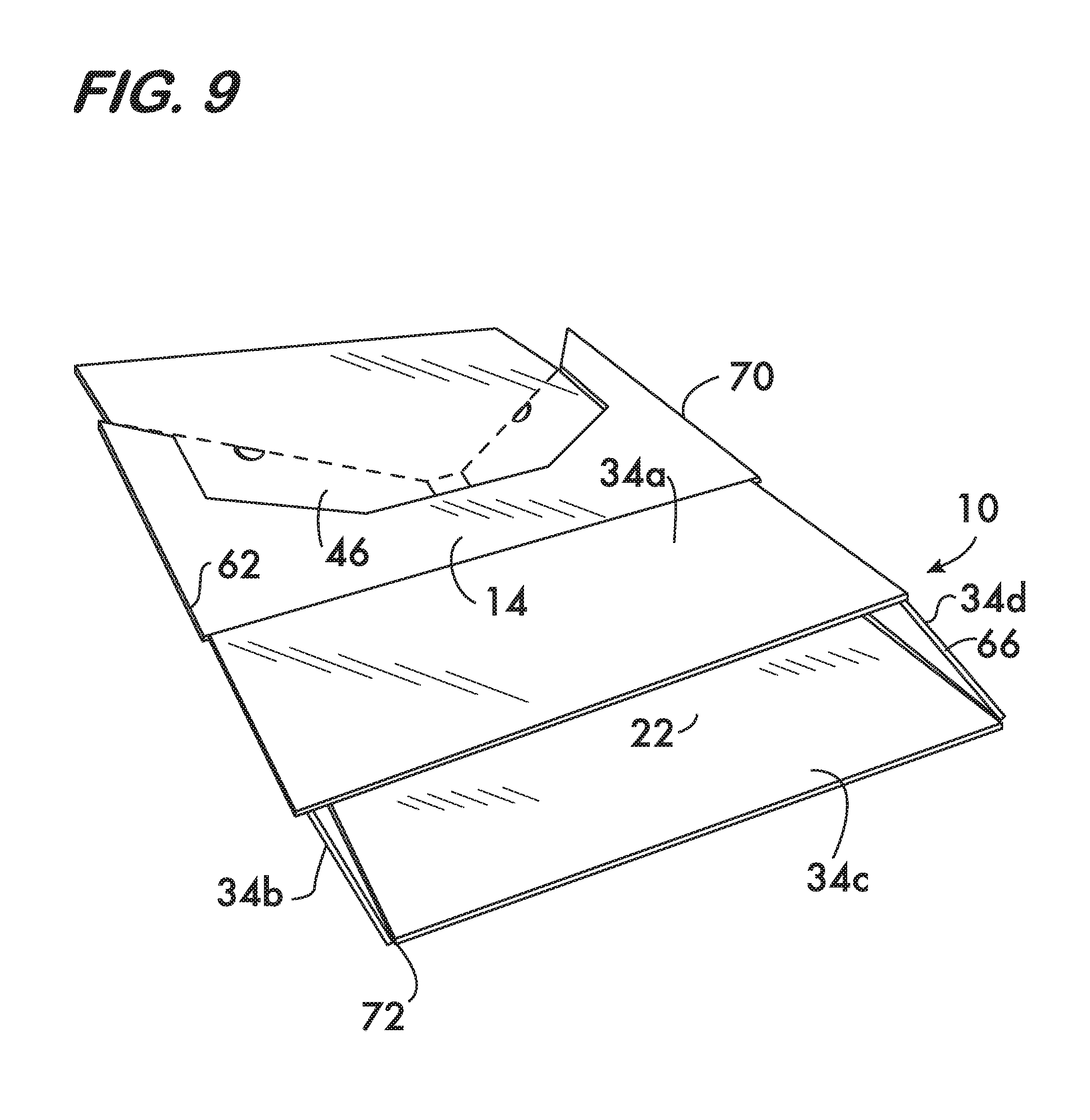
[0016] FIGS. 9-14 are perspective views showing the steps of assembling the container shown in FIG. 1 from the knockdown shown in FIG. 8;
[0017] FIG. 15 is a top partial view of the front side walls of the container shown in FIG. 1 with the inner removable cover section removed;
[0018] FIG. 16 is a front plan view of a display ready container in accordance with a second embodiment of the present invention showing the fully assembled closed container;
[0019] FIG. 17 is a perspective view of the container shown in FIG. 16;
[0020] FIGS. 18-20 are perspective views of the container shown in FIG. 16 showing steps of being opened to expose the display opening;
[0021] FIG. 21 is a plan view of a blank section for forming the container shown in FIG. 16;
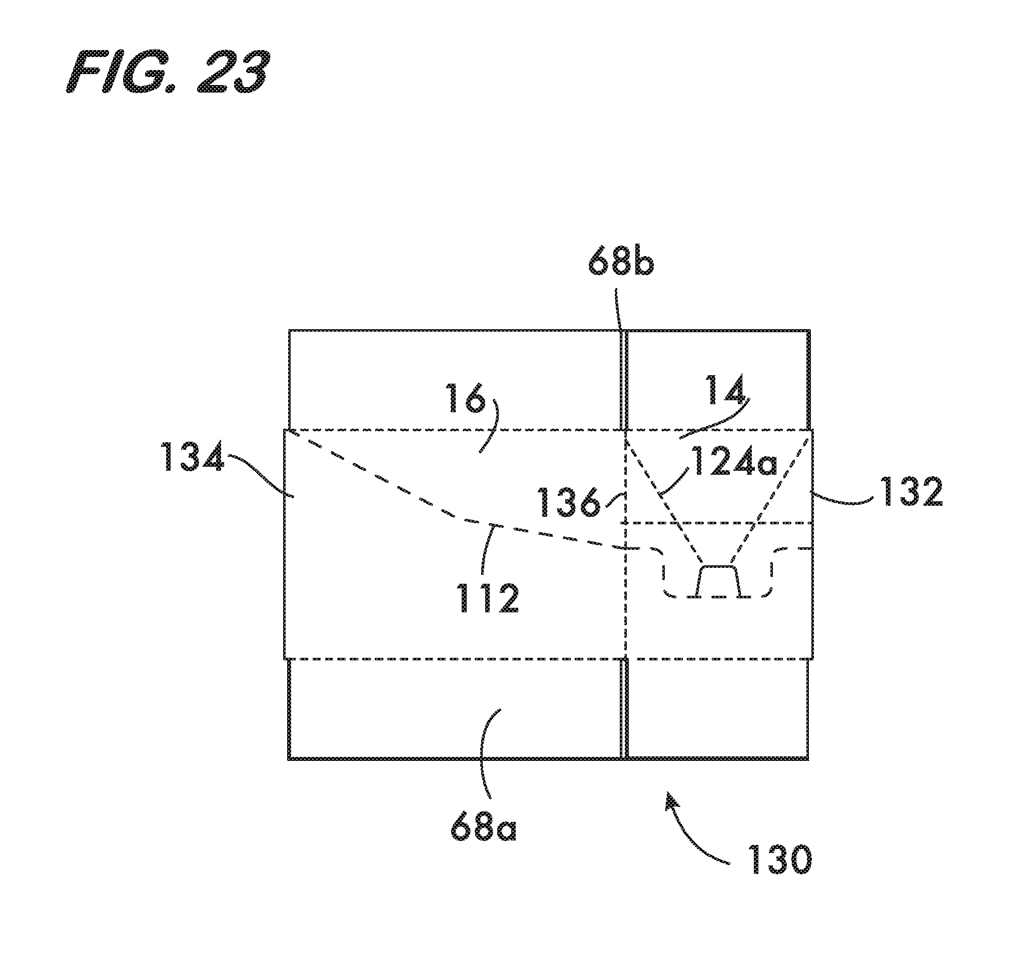
[0022] FIGS. 22-23 are perspective views showing the steps of forming a container knockdown from the blank shown in FIG. 21;
[0023] FIGS. 24-27 are views showing the steps of assembling the container shown in FIG. 16 from the knockdown shown in FIG. 23;
[0024] FIG. 28 is a top partial perspective view of the display opening looking outwardly from within the container shown in FIG. 21 with the display opening exposed;
[0025] FIG. 29 is a front plan view of a display ready container in accordance with a third embodiment of the present invention showing the fully assembled closed container;
[0026] FIG. 30 is a perspective view of the container shown in FIG. 30 being opened to expose the display opening;
[0027] FIG. 31 is a perspective top view of the container shown in FIG. 30 with the display opening fully exposed;
[0028] FIG. 32 is a perspective view of the container of FIG. 30 shown with the front and back side flaps open;
[0029] FIG. 33 is a plan view of a blank for forming the display ready container shown in FIG. 30;
[0030] FIG. 34 is a top plan view of a knock down form of the container shown in FIG. 29 formed from the blank shown in FIG. 33;
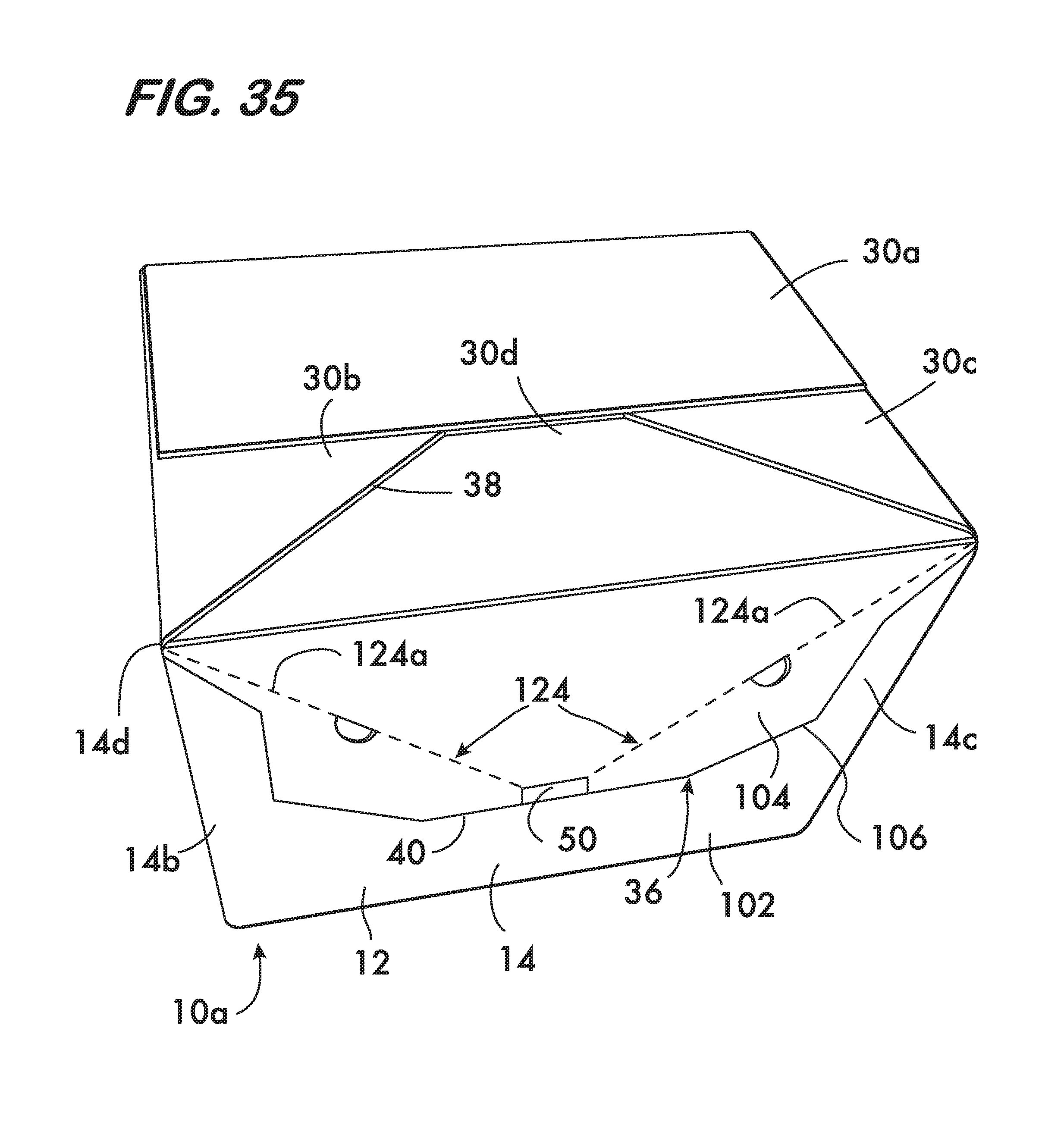
[0031] FIG. 35 is a perspective view of a display ready container assembly in accordance with a fourth embodiment of the present invention; and
[0032] FIG. 36 is a perspective view of the container assembly shown in FIG. 35 with the removable inner display cover section removed and shown below the now opened container.
DETAILED DESCRIPTION
[0033] The invention disclosed herein provides a novel display ready container, and a container knockdown assembly and blank therefore. Described below are illustrative embodiments of the invention for containers used for shipping and displaying goods for retail. It is understood, however, that the present invention is not so limited and can be adapted to other containers.
[0034] Reference now will be made in detail to the embodiment shown in FIG. 1 showing a fully erected display ready container assembly 10 in a closed form for shipping goods to the retailer. The container 10 has multiple container sidewalls 12 which include an outer front wall panel 14, inner front wall panel 15, first and second side wall panels 16, 18 (FIG. 5) which are adjacent to and on opposite sides of the front wall panels 14, 15, and a rear wall panel 20. The container sidewalls 12 have an inner face 22 (FIG. 5) facing an internal space 24 of the container 10, and an outer face 26 opposite the inner face 22.
[0035] Formed in the outer front wall panel 14 is a display opening 36 (see FIG. 5). The outer front wall panel 14 includes a lower front wall section 14a beneath the display opening 36 and first and second side sections 14b and 14c on opposing sides of the display opening 36, each of which has a tapered top end 19. It is seen that the outer front wall panel 14 has a display edge 40 extending from an upper corner 14d of one side of the wall panel 14 to an upper corner 14e on the opposite side of the wall panel 14, which edge 40 defines a lower boundary of the display opening 36.
[0036] In the illustrated embodiment, a container top 28 includes multiple top panels 30a, 30b, 30c and 30d, which can be folded to close the top of the container 10. The top panel 30a is attached integrally to the rear wall panel 20. Top panels 30b and 30c are attached integrally to the opposing side wall panels 16, 18, respectively, and each has an angled cut 38 defining a top section 36a of the display opening 36 upon exposure of the display opening as further described below. The top panel 30d is attached integrally to the top of the inner front wall panel 15.
[0037] A container bottom 32 includes bottom panels 34a, 34b, 34c, and 34d, each of which is attached integrally to a respective side wall panel 12 and can be folded to form the bottom 32 during assembly of the container 10. Any known type of container bottom may be used, including types that automatically move into position upon the opening of the container 10 from a knockdown state.
[0038] With reference to FIGS. 1, 6, 14, and 15, the inner front wall panel 15 is disposed against the inner face 22 of the outer front wall panel 14 so as to cover the display opening 36 and overlap the display edge 40. The inner front wall panel 15 has an inner removable cover section 44 and an inner remainder wall section 46 which are delineated by and separable from one another along a separation line 42. It is seen that the inner removable cover section 44 overlaps substantially the entire display edge 40, although alternative embodiments are contemplated where only portions of the display edge 40 are overlapped. In the illustrated embodiment, the inner removable cover section 44 overlaps a significant portion of the display edge 40, preferably by an amount within a range of and including about 1/8 to 1/2 inches. As discussed further below, this overlap helps to prevent premature separation of the inner removable cover section 44 from the inner remainder wall section 46 due to pressure from within the container 10 against the inner removable cover section 44. The greater the pressure within, the greater the overlap of the display edge 40 that may be desired to counter the pressure. The separation line 42 can be formed of any suitable means that allows the inner removable cover section 44 to be separated from the inner remainder wall section 46, such as a series of cuts or perforations that allow tearing of the container material.
[0039] With reference to FIGS. 1 and 2, an area of weakness 48 is formed in the inner removable display cover section 44. The area of weakness 48 is configured to deform the inner removable cover section 44 when pulled outwardly so as to decrease at least one of the width W1 and height H1 of the cover section 44 in a desired manner that allows the separation and removal of the inner removable cover section 44. This is illustrated in FIGS. 2 and 3 (the specific width W1 and height H1 may vary depending on where along the removable display cover section they are measured).
[0040] In the illustrated embodiment, the area of weakness 48 preferably includes two lines of weakness 48a forming a V-shaped configuration as shown, here extending from a central finger release opening 50. Lines of weakness 48a can be formed in any suitable manner and configuration that allows the container material to deform in a desired manner, and in the illustrated embodiment are formed by a series of perforations as seen in FIG. 2. As further described below, the area of weakness 48 is configured to provide a desired deformation in the inner removable cover section 44 that reduces its dimension(s) for removal through the display opening 36, which is smaller in width and/or height. The deformation may also help in the separation process of the inner removable cover section 44 from the inner remainder wall section 46. Additional finger release openings 50a can be provided in other places along the lines of weakness 48a as seen in FIG. 1 to aid in the deformation and removal process.
[0041] The present illustrated embodiment includes the top display opening section 36a as previously noted. This top display opening 36a is closed by the top panel 30d as seen in FIG. 1, and is opened by the removal of the top panel 30d as seen is FIGS. 3, 4 and 5. The top panel 30d is attached to the inner removable cover section 44 to be removable therewith as seen in FIG. 4 showing the inner removable cover section 44 separating from the inner remainder wall section 46 and the top panel 30d being removed from the container 10 (the remainder wall section 46 of the inner front wall panel 15 remains attached to the inner face 22 of the outer front wall panel 14).
[0042] The container 10 and the various panels described above can be made from any suitable materials, preferably corrugated paperboard. Moreover, as further described below, the container 10 can be formed preferably from a single integral sheet of material.
[0043] The container 10 is shown in FIG. 1 can hold goods within for shipment to the retailer. At the retailer, the display opening 36, including its top display opening section 36a, is opened by removal of the inner removable cover section 44 and the attached top panel 30d to expose the goods within.
[0044] Having described the general features of the container 10 in a fully erected enclosed form, the manufacture, assembly, and use of the container 10 are now described. See, e.g., FIG. 5 showing the container section 118 (removable cover section 44 and attached top panel 30d) removed from the display container remainder 120, which includes the display opening 36.
[0045] The manufacture and assembly of the container 10 begins preferably with the manufacture of a blank 52 in flat form, as illustrated in FIG. 6. The blank 52 is preferably die cut from a unitary sheet of corrugated paperboard and includes all the panel sections and flaps for forming the container 10. As customary in the industry, the view in FIG. 6 shows the inner face 22 of the various panels and flaps, the outer face 26 being on the underside not shown in this view. The various panels and flaps are delineated from one another along fold lines 54 preferably formed by scores formed in the corrugated material or any other suitable means of forming a line of weakness along which the panels and flaps will fold. Accordingly, as seen in FIG. 6, the blank 52 includes the multiple sidewalls 12, which include outer front wall panel 14, inner front wall panel 15, side wall panels 16 and 18, and rear wall panel 20 integrally attached along their side ends at fold lines 54. A cutout taken along the display edge 40 in the outer front wall panel 14 forms the display opening 36. The separation line 42 in the inner wall panel 15 is formed by a series of perforations that allow the inner removable cover section 44 to be removed (e.g., torn) from the inner remainder wall section 46. The lines of weakness 48a are formed by any suitable means, such as scores and/or perforations that allow the removable display cover section 44 to deform or bend about these lines in the desired configuration.
[0046] The blank 52 includes the bottom panels 34a through 34d integrally attached to a respective wall panel 12 along fold lines 54. Similarly, the top panels 30a through 30d are integrally attached to a top of a respective wall panel 12 along fold lines 54, although the top panel 30d is integrally attached to the top of the inner removable cover section 44 of inner wall panel 15 for removal therewith as described above. The finger release opening 50 is formed by a movable flap 51 cut into the blank 52 along the bottom and opposing sides of the opening 50 and which is foldable along the fold line 54 as shown. A user's finger can push open the flap 51 to access the opening 50. The additional finger release openings 50a can be formed as semicircle cutouts as shown in FIG. 1. The various other features and shapes can be formed at this stage as well, for example, the tapered top edges 19 of the outer front wall panel side sections 14b and 14c, and the angled cuts 38 in top panels 30b and 30c which ultimately form the top display opening section 36a.
[0047] The blank 52 can be folded to form a knockdown 60 (see FIG. 8) which can be erected into the final container assembly 10 shown in FIG. 1. The assembly of the knockdown 60 from the blank 52 is now described with further reference to FIGS. 6, 7 and 8. With initial reference to FIGS. 6 and 7, the inner front wall 15 together with bottom panel 34a and top panel 30d are folded as a substantially flat unit about the fold line 54 at corner 62 to position the inner face 22 of these panels onto the inner face 22 of side wall panel 16, among others, to form the assembly shown in FIG. 7.
[0048] An adhesive, such as a hot melt glue, is applied to the glue areas 64 (see FIG. 7) of the inner face 22 of the outer front wall panel 14. Alternatively, the glue could be applied onto the outer face 26 of the inner front wall 15 in glue areas 64a (see FIG. 7). With the adhesive in place, the side wall panel 18 together with top panel 30c, bottom panel 34d and outer front wall panel 14 are folded as a substantially flat unit about the fold line 54 at corner 66 to position the inner face 22 of front outer wall panel 14 onto the outer face 26 of the inner front wall 15 to form the knockdown assembly 60 shown in FIG. 8. The inner remainder wall section 46 of the inner front wall panel 15 is now adhered to the inner face 22 of the outer front wall panel 14.
[0049] The above-described process can be carried out automatically with modern machinery, the folds and glue being completed thereby. This forms the knockdown 60 having two substantially flat knockdown sections 68a, 68b (section 68b being disposed underneath 68a in FIG. 8) substantially parallel to one another and connected at the two opposing corner edges 62 and 66. These can be stacked for easy shipment to a packer where they can be assembled, packed with goods, sealed closed, and finally shipped to the retailer.
[0050] Assembly of the container 10 from the knockdown 60 is now described with further reference to FIGS. 9, 10, 11, 12, 13, and 14. With initial reference to FIGS. 8 and 9, the knockdown corners 62 and 66 are pushed toward each other, folding and forming the corners 70 and 72, until an erected container assembly 10 is formed as shown in FIG. 10. The bottom forming panels 34a-34d are then folded and taped or glued in position to form the container bottom 32 as shown in FIG. 11, readying the container assembly 10 to receive goods (the top 28 is shown open for receiving goods). Some bottom configurations, such as an auto bottom, do not require tape or glue.
[0051] Once the goods are loaded, the top 28 is formed to close the container 10. In this embodiment, the top panel 30d is removable for forming the display opening 36 and thus preferably is not glued or otherwise attached to any of the other top panels. Accordingly, the formation of the top 28 is effected by first folding front top panel 30d into position as shown in FIG. 12. With further reference to FIG. 13, the side top panels 30b and 30c are folded over the top panel 30d. Finally, the rear top panel 30a is folded over the side top panels 30b and 30c, and adhesive, tape or other means may be used to secure the rear top panel 30a in place to top panels 30b and 30c, but the front top panel 30d remains slidable for removal as shown in FIG. 15. This creates the closed assembled container 10 as shown in FIG. 1.
[0052] With further reference to FIGS. 1 through 5, the opening of the display opening 36 is now described. With specific reference to FIGS. 1, 2 and 3, the user pushes his or her finger into the finger release opening 50, pushing in the tab 51, and then pulls the inner removable cover section 44 outward. As seen in FIG. 2, the inner removable cover section 44 deforms along the area of weakness 48, bending around the V-shaped lines 48a. This action helps separate the inner removable cover section 44 from the inner remainder wall section 46 which remains adhered to the inner face 22 of the outer front wall panel 14. It is further appreciated that the deformation along the lines 48a, which extend at an angle in both the width W1 and height H1 dimensions, causes the inner removable cover section 44 to decrease in both the width W1 and height H1, which helps separation from the inner remainder wall section 46 along separation line 42, while also reducing the dimensions of the inner removable cover section 44 sufficiently to ease its removal as it is pulled through the display opening 36. The deformation desired diminishes the width and height dimensions sufficiently to allow removal of the inner removable cover section 44 past the display edge 40 of the inner front wall panel 15. The deformation configuration also cooperates with the particular shape of the display opening 36. Once the inner removable display cover section 44 has been separated from the inner remainder section 46, the inner removable cover section 44 is pulled forward to slide the top panel 30d from the container 10 as seen in FIG. 4. This creates the display opening 36, with top display opening section 36a, allowing access to the internal space 24 as seen in FIG. 5.
[0053] As noted previously, the area of weakness 48 is configured to provide the desired deformation of the removable display cover section 44. The V-shaped weakness lines 48a extend in both the width W1 and height H1 directions to provide a deformation that reduces both the width W1 and height H1 dimensions of the inner removable cover section 44. An area of weakness 48 formed as a vertical line would allow deformation to reduce the width. An area of weakness 48 formed as a horizontal line would allow deformation to reduce the height. Thus, it is appreciated that the angled two lines of the V-shaped area of weakness 48, having both vertical and horizontal components, reduce both width and height of the inner removable cover section 44. Other configurations for the area of weakness 48 are contemplated. For example, it may be possible to provide a curved line, a combination of different shaped lines, or multiple short lines aligned or parallel to one another. Sufficient weakening should be provided to create the desired deformation.
[0054] It is further appreciated that the inner remainder wall section 46 is attached, e.g., adhered with glue, to the inner face 22 of the outer front wall panel 14. This will hold the inner remainder wall section 46 in place to allow the inner removable cover section 44 to be separated therefrom while also holding the container together.
[0055] Another advantage of the present invention is that the overlap of the inner removable cover section 44 over the display edge 40 on the front wall panel 14 provides strength and reinforcement so that the contents within the container 10 are less likely to cause premature separation along the separation line 42. The heavier the internal contents or the more likely the internal contents are to push on the inner removable cover section 44, a bigger overlap of the display edge 40 may be preferable, although the bigger the overlap, the more deformation that may be required to remove the removable inner cover section 44. The overlap can be any suitable amount, preferably within the range of and including about 1/8 inch to 1/2 inch in length, and more preferably within a range of about 1/8 inch to 1/4 inch, although other overlaps are contemplated.
[0056] A further advantage is now described with reference to FIG. 15, which shows the container 10 with the inner removable cover section 44 removed to expose the display opening 36. The inner remainder wall section 46 is seen adhered against the inner face 22 of the outer front wall panel 14. It is seen that the separation line 42, along which the inner removable cover section 44 separates from the inner remainder wall section 46, is spaced from the display edge 40. This spacing is the overlap of the removable inner cover section 44 over the display edge 40 onto the inner face 22 of the outer front wall panel 14 (see, e.g., overlap 56 in FIG. 28 showing another embodiment of the invention that is described below). It is appreciated that when the removable inner cover section 44 is separated from the inner remainder wall section 46, a process that tears the material of the container 10, rough and unsightly edges along the separation line 42 can be created. By spacing the separation line 42 below the display edge 40 as shown, the rough edges are not visible to the customers. The display edge 40, cut during the formation of the blank 52 and visible to customers, will have a clean presentable edge.
[0057] A second embodiment of the present invention is now described with reference to FIGS. 16-28. With initial reference to FIGS. 16 to 20, the display ready container 100 of the second embodiment can be opened by deforming panel sections to effect the opening of the display opening. In this embodiment, the display opening 36 includes a portion of the front wall panel, and portions of the side wall panels and the top panel (see FIGS. 19 and 20). One difference of the second embodiment from the previous one is the addition of an outer removable display panel section 104 that forms part of the outer front wall panel 14, but is removable with the inner removable cover section 44 to expose the display opening 36. This embodiment is now described in further detail with like elements identified with the same reference numbers as used above.
[0058] With reference to FIGS. 16, 17 and 18, the display ready container 100 has multiple container sidewalls 12 which include outer front wall panel 14, inner front wall panel 15 (FIGS. 16, 19 and 21), first and second side wall panels 16, 18 which are adjacent to and on opposite sides of the front wall panels 14, 15, and rear wall panel 20. The container sidewalls 12 have an inner face 22 facing an internal space 24 of the container 100 and an outer face 26 opposite the inner face 22.
[0059] Formed in the outer front wall panel 14 is a portion of a display opening 36 (see also FIG. 19) which is shown filled in or closed by an outer removable wall section 104 as further described below. The front wall panel 14 includes a lower front wall panel section 14a beneath the display opening 36 and first and second side shoulders 14b and 14c on opposing sides of the front section of the display opening 36. The front wall panel 14 has a display edge 40 extending from one side of the outer wall panel 14 to the other side and which defines a lower boundary of the display opening 36 in the front wall panel 14 as shown. The front wall panel 14 further includes an outer remainder front wall section 102 and the outer removable wall section 104 delineated and separable from one another by a front wall separation line 106 which forms the display edge 40. It is seen that the outer remainder front wall section 102 includes the lower front wall panel section 14a and first and second side sections 14b and 14c, as well as the display edge 40.
[0060] Each of the side wall panels 16 and 18 include a side wall remainder section 108 and a removable side wall section 110 separable from one another along a side wall separation line 112. The separation line 112 can be a series of perforations or any other suitable form. As discussed further below, the removable side wall section 110 of each side wall panel 16, 18, are removed to expose side display portions 36b of the display opening 36. It is further seen that the separation line 112 on each side wall panel 16, 18 extends approximately from and/or is adjacent to an end 106a of the separation line 106.
[0061] A container top 28 includes multiple top panels 114a, 114b, 114c and 114d, which are folded to close the top of the container 10. The top panels 114a and 114b are attached integrally to respective side wall panels 16 and 18. The top panel 114c is attached integrally to the top of the inner removable cover section 44. The top panel 114d is attached integrally to the top of the rear wall panel 20 and separable therefrom along separation line 116. As will be described below, in the illustrated embodiment, the entire top 28, i.e. all of the top panels 114a, 114b, 114c and 114d, along with the removable side wall sections 110 and the inner and outer removable wall panel sections 44, 104, all as a removable unit 118, is removable from a remainder 120 of the container 100 to form the display opening 36 (see FIGS. 19, 20).
[0062] A container bottom 32 includes bottom panels 34a, 34b, 34c, and 34d attached to respective side wall panels. Each of the bottom panels can be folded to form the bottom 32 during assembly of the container 100. Any known type of container bottom may be used, including automatically forming bottoms.
[0063] With reference to FIGS. 19, 20, 21, and 28, the inner front wall panel 15 is disposed against, and preferably adhered thereto, the inner face 22 of the front wall panel 14 to cover the display opening 36 and overlap the display edge 40. The inner front wall panel 15 has an inner removable cover section 44 and an inner remainder wall section 46 delineated and separable from one another by a separation line 42. It is seen that the inner removable cover section 44 overlaps the display edge 40 and extends onto the inner surface 22 of the outer lower wall panel section 14a.
[0064] An area of weakness 48 formed in the inner removable cover section 44 causes the section 44 to deform when pulled outwardly so as to reduce at least one of its width W1 and height H1 dimensions in a desired manner to effect its separation and removal from the inner remainder wall section 46. This is illustrated in FIGS. 18, 19 and 20. As in the prior described embodiment, the area of weakness 48 includes two lines of weakness 48a forming a V-shaped configuration extending from a finger release opening 50 as shown through which a user can pull the inner removable cover section 44 for separation and removal.
[0065] A second area of weakness 124 is formed in the outer removable section 104 of the outer wall 14, which is also configured to deform when pulled outwardly. This second area of weakness 124, preferably V-shaped lines 124a, is configured to cooperate with the area of weakness 48 in the inner removable cover section 44 (the first area of weakness) to allow both sections 44 and 104 to deform together in the desired manner to effect separation of both sections 44, 104 along respective separation lines 42 and 106. Preferably, the two areas of weakness, here the V-shaped lines 48a, 124a, are substantially adjacent to one another to effect the deformation process in unison. It is further appreciated that the deformation of the sections 44 and 104 outwardly as seen in FIGS. 18, 19 pulls the side wall panels 16, 18 inwardly helping to effect the separation of the removable side wall sections 110 from the side wall remainder sections 108 along separation lines 112. As the user continues to pull sections 44 and 104 outwardly and upwardly, the entire display section 36 is exposed as the front outer and inner removable sections 44, 104, removable side wall sections 110, and the entire top 28 (top panels 30a through 30d) are separated as a single unit 118 from the remainder 120 of the display ready container 100, which is finally separated along separation line 116 (see FIGS. 19 and 20). Additional areas of weakness can be provided to aid in the deformation and separation process. These will be explained further below with reference to a blank 122.
[0066] With further reference to FIG. 21, a blank 122 is preferably die cut from a unitary sheet of corrugated paperboard, with all the panel and flap sections for forming the container 100. The various panels and flaps are delineated from one another along fold lines 54 formed preferably by scores in corrugated paperboard material or any other suitable means of forming a line of weakness for folding.
[0067] The blank 122 includes the multiple sidewalls 12, which include outer front wall panel 14, inner front wall panel 15, side wall panels 16 and 18, and rear wall panel 20 integrally attached along their side ends at fold lines 54. The display opening 36, at least the front portion of the display opening, is formed partially along the display edge 40 in the outer front wall panel 14. The separation lines 42, 106, 112, and 116 are formed by a series of perforations that allow the entire display removal unit 118 to be removed, (e.g., torn) from the display container remainder 120 (FIG. 20). The lines of weakness 48a, 124a are formed by any suitable means, such as scores and/or perforations that allow the desired deformation.
[0068] The blank 122 includes the bottom panels 34a through 34d and top panels 114a through 114d as shown. A cutout forms the outer finger release opening 50; the inner finger release opening has a movable flap 51 cut into the blank. The various other features and shapes are formed preferably at this stage as well. For example, the areas of weakness 48, 124 (e.g., lines 48a, 124a) are formed by perforations. Added lines of weakness to aid in the desired deformations can be provided, such as scores 126 formed on the inner face 22 of the removable side wall sections 110 (helping the sections deform inwards) and horizontal scores 128 on the inner and outer removable wall panels 44, 104 as shown.
[0069] The blank 122 can be folded to form a knockdown 130 (see FIG. 23) which can be erected into the final container assembly 100 shown in FIG. 16. The assembly of the knockdown 130 is now described with further reference to FIGS. 22 and 23. With initial reference to FIGS. 21 and 22, the inner wall panel 15 together with bottom panel 34a and top panel 114c are folded as a substantially flat unit about the fold line 54 at corner 132 to position the inner face 22 of the panels onto the inner face 22 of side wall panel 18, bottom panel 34d and top panel 114b to form the assembly shown in FIG. 22.
[0070] An adhesive, such as a hot melt glue, is applied to the glue areas 64 (see FIG. 21) of the inner face 22 of the outer wall panel 14 (alternatively, the glue can be applied onto the outer face 26 of the outer wall panel 15). With the adhesive in place, the side wall panel 16 and outer wall panel 14, with the bottom panel and top panels attached thereto, are folded as a substantially flat unit about the fold line 54 at corner 134 to position the inner face 22 of outer front wall panel 14 onto the outer face 26 of the inner front wall panel 15 to form the knockdown assembly 130 shown in FIG. 23. The outer front wall panel 14 and inner front wall panel 15 are thus adhered together, aiding the removal of the inner removable cover section 44 and outer removable wall section 104 together.
[0071] The above-described process can be carried out automatically with machinery. The knockdown 130 is seen having two substantially flat knockdown sections 68a, 68b (sections 68b being disposed underneath 68a in FIG. 23) substantially parallel to one another connected at the two opposing corners 132 and 134.
[0072] Assembly of the container 100 from the knockdown 130 is described with further reference to FIGS. 24, 25, 26 and 27. The knockdown corners 132 and 134 are pushed toward each other, folding and forming the corners 136 and 138, until an erected container assembly 10 is formed as shown in FIG. 25. The bottom forming panels 34a-34d can then be folded and either taped or glued into position to form the container bottom 32 as shown in FIG. 26, readying the container assembly 100 to receive goods (the top 28 is shown open for receiving goods). Once the goods are loaded, the top 28 is formed to close the container 10. This is done by folding the top panels 114a, 114b, 114c, and 114d as seen in FIG. 29. This creates the closed assembled container 100 shown in FIG. 16.
[0073] With further reference to FIGS. 18 through 20, the opening of the container 100 is now described. With specific reference to FIGS. 18 and 19, the user's finger in the finger release opening 50 pulls outward the inner removable cover section 44 and outer removable wall section 104 as a unit. The two sections 44, 104 deform along the area of weaknesses 48, 124 bending around the V-shaped lines 48a, 124a. This action helps separate the inner removable cover section 44 from the inner remainder wall section 46, which remains adhered to the inner face 22 of the front wall panel 14, and separate the outer removable wall section 104 from the outer remainder wall section 102. The deformation along the lines 48a, 124a, which extend at an angle in both the width W1 and height H1 dimensions causes a decrease of both the removable inner cover section 44 and outer wall section 104 in both the width and height, to help separate from the remainder sections 46, 102 and help the two removable Sections 44, 104 fit through the front of the display opening 36. This deformation of the width W1 of the sections 44, 104 also pulls inwardly the removable side wall sections 110, helping them to separate from remainder sidewall sections 108. The line of weakness 112 on the inner face 22 of the removable side wall sections 110, helps with the separation (FIGS. 17 and 21). Once the inner and outer removable front sections 44, 104 have been separated from the remainder sections 46, 102, the entire separated container section 118 is pulled upwardly, rotating around separation line 116 in the upper rear corner to fully expose the display opening 36 which here includes a portion of the front wall panels, side panels and the complete top 28. The removable container section 118 is torn along separation line 116 to form the two sections 118, 120 as seen in FIG. 20.
[0074] With further reference to FIG. 28, the overlap 56 provided for the inner removable cover section 44 (here removed) over the display edge 40 of the outer front wall 14 is illustrated.
[0075] An advantage of the present embodiment is the added strength provided by the outer removable wall section 104 to minimize premature separation of the removable panels 44, 104. This embodiment is a top load container in that the goods are loaded through the top opening before the top 28 is closed.
[0076] A third embodiment, similar to that of the second embodiment described above, but which is a side load container 200, is now described with reference to FIGS. 29 to 34. This container 200 is very similar to that above and like elements will be referenced with the same reference numbers.
[0077] With initial reference to FIGS. 29 to 32, the container 200 has multiple container sidewalls 12 which include an outer front wall panel 14, inner front wall panel 15, first and second side wall panels 16, 18, which are adjacent to and on opposite sides of the front wall panels 14, 15, and rear wall panels 20a, 20b, 20c and 20d. Top panel 202 forms a container top 28 and bottom panel 204 forms the container bottom 32. The container sidewalls 12 have an inner face 22 facing an internal space 24 of the container 200 and an outer face 26 opposite the inner face 22. As seen in FIGS. 30 and 31, the container 200 is opened to expose the display opening 36 in a similar manner as that of container 100 described above with reference to FIGS. 20 and 22. As will be further described below, differences between the container 200 as compared to container 100 include the following: container 200 is loaded with goods through openings in one of the front or rear prior to the closure of the opened side wall (container 100 is loaded from the top), and only a portion of the container top 28 is removed when exposing the display opening 36 (the entire top of container 100 is removed).
[0078] The outer and inner front wall panels 14 and 15 are configured the same as that for container 100 described above, including inner removable cover section 44 and outer removable wall section 104, and will not be further described. Likewise, the first and second areas of weaknesses 48 and 124 are configured the same as that for container 100 described above and will not be further described.
[0079] Each of the side wall panels 16 and 18 include a side panel remainder section 108 and a removable side wall section 110 separable from one another along a side wall separation line 112 extending approximately from and/or is adjacent to an end 106a of the separation line 106.
[0080] The top panel 202 has a top panel remainder section 206 and a top panel removal section 208 separable from one another along a top separation line 210 extending between and adjacent to the opposing side wall separation lines 112 so that the top panel removal section 206 is removable with the removable side wall sections 110 for forming a top portion 36a of the display opening 36 (see FIG. 30).
[0081] As seen in FIGS. 30 and 31, the container 200 is opened similarly as is container 100 to expose the display opening 36. The inner removable cover section 44 and outer removable wall section 104 are pulled in an outward direction to separate and remove these sections along with the removable top section 208 and the removable side wall sections 110, as a unit 118, from the remainder of the container 120.
[0082] A blank 212 for forming the container 200 is described with reference to FIG. 33. Preferably cut from a unitary sheet of corrugated paperboard, the blank 212 includes side wall panel 16, top panel 202, side wall panel 18, and bottom panel 204, integrally attached along their side ends at fold lines 54. The inner front wall panel 15 is integrally attached to an end of the side wall panel 16 along fold line a 54 as shown. Similarly, the outer front wall panel 14 is integrally attached to an end of the side wall panel 18 along a fold line 54 as shown. The display opening 36, at least the front portion of the display opening, is formed partially along the display edge 40 in the outer front wall panel 14. The separation lines 42, 106, 112, and 210, formed by a series of perforations, and the lines of weakness 48a, 124a, formed by any suitable means, are likewise shown. A glue tab 214 is attached to the end of side wall 16. Two additional front flaps 216a, 216b are preferably provided, the front flap 216b being attached to the bottom flap 204 to help provide a closed bottom front edge when folded. The outer finger release opening 50 is formed by a cut out; the inner finger release opening has a movable flap 51 cut into the blank. Additional lines of weakness--horizontal scores 128 in the inner face 22 of the inner and outer removable wall panels 44, 104 are also provided in this embodiment.
[0083] The blank 212 can be folded to form a knockdown 218 (see FIG. 34) which can be erected into the final container assembly 200. With further reference to FIGS. 33 and 34, the side wall panel 16 together with glue tab 214, inner front wall panel 15 and rear panel 20a are folded as a substantially flat unit about the fold line 54 at corner 220 to position the inner face 22 of these panels onto the inner face 22 of top panel 202. An adhesive, such as a hot melt glue, is applied to the outer face 26 of the glue joint (the underside of the glue joint 214 shown in FIG. 33), and then bottom panel 204 with the panels 20b and 216b attached thereto, are folded as a substantially flat unit about the fold line 54 at corner 222 to position the bottom panel 204 onto the outer face 26 of the glue tab 214 to form the knockdown assembly 218 shown in FIG. 34. The knockdown 218 is seen having two substantially flat knockdown sections 68a, 68b (sections 68b being disposed underneath section 68a in FIG. 34) substantially parallel to one another connected at the two opposing corners 220 and 222.
[0084] To assemble the container 200 from the knockdown 218, the knockdown corners 220 and 222 are pushed toward each other, folding and forming the corners 224 and 226 as seen in FIG. 32 showing the container 200 resting on its side wall 18. The rear panels 20a through 20d, and inner and outer front panels 14 and 15, are shown unfolded in FIG. 32. The goods can then be loaded into the container 200 through the opening in either the rear or front of the container 200. For example, if the goods are to be frontloaded, i.e., through the front opening, the rear panels 28a through 20d will be folded along fold lines 54 to close the bottom of the container. The goods would then be added through the front opening and then the front flaps 216a and 216b will be folded, inner front wall panel 15 will be folded over front flaps 216a and 216b, glue will be applied on the outer face 26 of the inner front wall panel 15 along both the inner removable cover section 44 and inner remainder wall section 46, and finally the outer front wall panel 14 will be folded onto the inner front wall 15 to be adhered thereto. This creates the closed assembled container 200 shown in FIG. 29.
[0085] The container 200 is opened in the same manner as the container 100 described above, and is illustrated in FIGS. 30 and 31. The two sections 44, 104 deform along the area of weaknesses 48, 124 as described above in regard to container 100.
[0086] A fourth embodiment of the present invention is now described with reference to FIGS. 35 and 36. This container assembly 10a of this embodiment is very similar to that of the container 10 shown in FIG. 1 and can be formed with a blank similar to that shown in FIG. 6 but modified to include the extra panel described below. The main substantive difference between the embodiment shown in FIG. 35 and that of FIG. 1 is the addition of an outer removable display panel section 104 similar to that of container 100 of the embodiment of FIG. 16. The elements that are the same as those described above are identified with the same reference numbers.
[0087] As noted above, container 10a is essentially identical to that of container 10 described above with the addition of the outer removable display panel section 104 which closes the display opening 36 formed in the front outer wall panel 14. The front wall panel 14 includes an outer remainder front wall section 102 from which the outer removable wall section 104 is delineated by a front wall separation line 106 which forms the display edge 40. This removable display panel section 104 is separable from the remainder front wall section 102 along the separation line 106 to expose the display opening when removed. A second area of weakness 124 is formed in the outer removable section 104 via V-shaped lines 124a, which is configured to cooperate with the area of weakness 48 of the inner removable cover section 44 (the first area of weakness) to allow both sections 44 and 104 to deform together in the desired manner to affect separation and removal of both sections 44, 104 along their respective separation lines 42 and 106. Preferably, the two areas of weakness 48, 124 are substantially adjacent to one another to effect the formation process in unison.
[0088] A blank similar to that shown if FIG. 6 can be used for this container assembly 10a. Here, the outer removable display panel section 104 will be provided as part of the outer front wall panel 14 within the display opening 36, delineated therefrom for separation along separation line 106 by perforations or other type of separation line. The outer removable display panel section 104 is preferably adhered to the inner removable cover section 44.
[0089] With further reference to FIG. 36, the container section 118 is shown removed from the remainder of the display container remainder 120. The container section 118 includes the removable top section 30d integrally attached to the removable cover sections 44 and 104. The overlap 56 of the inner removable section 44 over the display edge 40 of the front wall 14 is illustrated. It is appreciated that this overlap 56 will correspond to the overlap on the inside of the container 10a after removal of the outer removable display panel section 104, and will look similar to that as shown in FIG. 15, which shows the overlap between the inner and outer edges 40 and 42.
[0090] While particular embodiments of the invention are described herein, it is not intended to limit the invention to such disclosure. Changes and modifications may be incorporated and embodied within the scope of the appended claims.
* * * * *
D00000
D00001
D00002
D00003
D00004
D00005
D00006
D00007
D00008
D00009
D00010
D00011
D00012

D00013

D00014

D00015

D00016

D00017

D00018

D00019

D00020

D00021

D00022

D00023
D00024

D00025

D00026

D00027

D00028

D00029

D00030

D00031

D00032

D00033

D00034

D00035
D00036

XML
uspto.report is an independent third-party trademark research tool that is not affiliated, endorsed, or sponsored by the United States Patent and Trademark Office (USPTO) or any other governmental organization. The information provided by uspto.report is based on publicly available data at the time of writing and is intended for informational purposes only.
While we strive to provide accurate and up-to-date information, we do not guarantee the accuracy, completeness, reliability, or suitability of the information displayed on this site. The use of this site is at your own risk. Any reliance you place on such information is therefore strictly at your own risk.
All official trademark data, including owner information, should be verified by visiting the official USPTO website at www.uspto.gov. This site is not intended to replace professional legal advice and should not be used as a substitute for consulting with a legal professional who is knowledgeable about trademark law.