Unmanned Aerial Vehicle Take-off And Landing Control System And Control Method
HU; Tengfei
U.S. patent application number 16/060888 was filed with the patent office on 2019-01-10 for unmanned aerial vehicle take-off and landing control system and control method. This patent application is currently assigned to GoerTek Technology Co., Ltd.. The applicant listed for this patent is GOERTEK TECHNOLOGY CO., LTD.. Invention is credited to Tengfei HU.
| Application Number | 20190009926 16/060888 |
| Document ID | / |
| Family ID | 56297782 |
| Filed Date | 2019-01-10 |

| United States Patent Application | 20190009926 |
| Kind Code | A1 |
| HU; Tengfei | January 10, 2019 |
UNMANNED AERIAL VEHICLE TAKE-OFF AND LANDING CONTROL SYSTEM AND CONTROL METHOD
Abstract
Disclosed is an unmanned aerial vehicle take-off and landing control system and a control method. The system comprises a magnet assembly at the side of an unmanned aerial vehicle and a magnetic field assembly at the side of a parking platform. An electrified coil is provided in the magnetic field assembly and current is supplied into the coil. A magnetic field is generated by the magnetic field assembly to form a thrust force acting on the unmanned aerial vehicle. A resultant force is formed by the thrust force and a lift or resistance force in the process of take-off or landing of the unmanned aerial vehicle to supplement the lift force or resistance. In this process, the current in the coil is changed to form a uniform magnetic field, the thrust force acting on the unmanned aerial vehicle is generated to supplement the lift force or the resistance.
| Inventors: | HU; Tengfei; (Qingdao City, CN) | ||||||||||
| Applicant: |
|
||||||||||
|---|---|---|---|---|---|---|---|---|---|---|---|
| Assignee: | GoerTek Technology Co.,
Ltd. Qingdao City, Shandong CN |
||||||||||
| Family ID: | 56297782 | ||||||||||
| Appl. No.: | 16/060888 | ||||||||||
| Filed: | December 22, 2016 | ||||||||||
| PCT Filed: | December 22, 2016 | ||||||||||
| PCT NO: | PCT/CN2016/111573 | ||||||||||
| 371 Date: | June 8, 2018 |
| Current U.S. Class: | 1/1 |
| Current CPC Class: | B64F 1/02 20130101; H01F 7/202 20130101; B64F 1/04 20130101; B64C 2201/066 20130101; B64C 2201/088 20130101; H02J 7/025 20130101; H02N 15/00 20130101; B64C 2201/021 20130101; B64C 2201/208 20130101; B64C 2201/18 20130101; B64F 1/362 20130101; B64C 39/024 20130101 |
| International Class: | B64F 1/04 20060101 B64F001/04; B64F 1/02 20060101 B64F001/02; B64C 39/02 20060101 B64C039/02; B64F 1/36 20060101 B64F001/36; H01F 7/20 20060101 H01F007/20; H02N 15/00 20060101 H02N015/00; H02J 7/02 20060101 H02J007/02 |
Foreign Application Data
| Date | Code | Application Number |
|---|---|---|
| Dec 31, 2015 | CN | 201511014413.6 |
Claims
1. An unmanned aerial vehicle take-off and landing control system, comprising: a magnet assembly provided at the side of the unmanned aerial vehicle; a magnetic field assembly provided at the side of a landing platform, wherein an electrified coil is provided in the magnetic field assembly; the electrified coil is supplied with a current, and the magnetic field assembly generates a supporting magnetic field at the side of the landing platform, to form a thrust force that acts on an unmanned aerial vehicle; and a resultant force is formed by the thrust force and a lift force of the unmanned aerial vehicle in the process of take-off or landing of the unmanned aerial vehicle or a resistance force that acts on the unmanned aerial vehicle, to supplement the lift force or the resistance force; wherein after the air gap is formed between the unmanned aerial vehicle and the landing platform, the wing of the unmanned aerial vehicle starts to rotate; the forward current supplied into the electrified coil decreases with the increasing of the rotational speed of the wing of the unmanned aerial vehicle; and when the rotational speed of the wing of the unmanned aerial vehicle is equal to a preset rotational speed, the current supplied into the electrified coil decreases to zero.
2. The unmanned aerial vehicle take-off and landing control system according to claim 1, further comprising a rotational speed measuring device, a distance measuring device and a controller; the rotational speed measuring device measures a rotational speed of a wing of the unmanned aerial vehicle, the distance measuring device measures a distance between the unmanned aerial vehicle and a predetermined parking location; and the controller changes the direction and the magnitude of the current supplied into the electrified coil according to the rotational speed obtained by the rotational speed measuring device and/or the distance obtained by the distance measuring device.
3. The unmanned aerial vehicle take-off and landing control system according to claim 2, wherein the controller receives a take-off instruction, and controls the electrified coil to be supplied with a forward current which is continuously increased, and the supporting magnetic field generates an upward thrust force that acts on the unmanned aerial vehicle; and when the thrust force acting on the unmanned aerial vehicle by the supporting magnetic field is equal to a gravity of the unmanned aerial vehicle, the forward current supplied into the electrified coil reaches its maximum, and an air gap is formed between the unmanned aerial vehicle and the landing platform.
4. The unmanned aerial vehicle take-off and landing control system according to claim 3, wherein the controller receives a landing instruction, and the distance measuring device detects whether the distance between the unmanned aerial vehicle and the landing platform is within a landing allowable range; and if the distance between the unmanned aerial vehicle and the landing platform is within the landing allowable range, the rotational speed of the wing of the unmanned aerial vehicle keeps unchanged, and the controller controls a reverse current to be supplied into the electrified coil to drag the unmanned aerial vehicle to right above the predetermined parking location.
5. The unmanned aerial vehicle take-off and landing control system according to claim 4, wherein after the unmanned aerial vehicle is dragged right above the predetermined parking location, the controller controls the electrified coil to be supplied with a forward current which is continuously increased; and when the rotational speed of the wing of the unmanned aerial vehicle is zero and the distance measuring device detects that the distance between the unmanned aerial vehicle and the landing platform is zero, the controller stops electrifying the electrified coil.
6. (canceled)
7. The unmanned aerial vehicle take-off and landing control system according to claim 5, further comprising an energy storage device provided, in the unmanned aerial vehicle and a charge coil provided on an undercarriage of the unmanned aerial vehicle, wherein the energy storage device and the charge coil are electrically connected; when the unmanned aerial vehicle is flying, the energy storage device and the charge coil are disconnected; when the unmanned aerial vehicle is parking on the landing platform, the controller controls the electrified coil to be supplied with a charging current, the magnetic field assembly generates a varying charging magnetic field at the side of the landing platform, and the energy storage device and the charge coil are connected to charge the energy storage device.
8. The unmanned aerial vehicle take-off and landing control system according to claim 7, wherein the distance measuring device comprises an infrared distance measuring device provided in the unmanned aerial vehicle and an infrared receiving device provided at the side of the landing platform, and the width of the infrared receiving device is greater than the width of the infrared distance measuring device.
9. The unmanned aerial vehicle take-off and landing control system according to claim 8, wherein the magnet assembly comprises a permanent magnet provided on a corresponding contact surface between the undercarriage of the unmanned aerial vehicle and the landing platform, and the magnetic field assembly comprises an iron core provided at the landing platform, and the electrified coil is wound around the iron core.
10. A control method for controlling take-off and landing of an unmanned aerial vehicle by using the unmanned aerial vehicle take-off and landing control system according to claim 9, wherein the method comprises the following steps: S1, the controller receives the take-off instruction, controls the electrified coil to be supplied with the forward current which is continuously increased; and when the thrust force acting on the unmanned aerial vehicle by the supporting magnetic field is equal to a gravity of the unmanned aerial vehicle, the forward current supplied into the electrified coil reaches its maximum, and an air gap is formed between the unmanned aerial vehicle and the landing platform; S2, after the air gap is formed between the unmanned aerial vehicle and the landing platform, the maximum forward current supplied into the electrified coil is controlled by the controller to be unchanged, and the wing of the unmanned aerial vehicle starts to rotate; a rotational speed detection signal that is fed back by a rotational speed detecting device is inputted to an input end of the controller, and a controlling signal is outputted according to the inputted rotational speed detection signal to control the forward current supplied into the electrified coil to decrease with the increasing of the rotational speed of the wing of the unmanned aerial vehicle; when the rotational speed of the wing of the unmanned aerial vehicle is equal to a preset rotational speed, the current supplied into the electrified coil is controlled by the controller to decrease to zero; S3, the controller receives a landing instruction, and the distance measuring device detects whether the distance between the unmanned aerial vehicle and the landing platform is within a landing allowable range; S4, if the distance between the unmanned aerial vehicle and the landing platform is within the landing allowable range, the controller inputs a controlling signal to keep the rotational speed of the wing of the unmanned aerial vehicle unchanged, and controls the electrified coil to be supplied with a reverse current to drag the unmanned aerial vehicle to right above a predetermined parking location; S5, the electrified coil is controlled by the controller to be supplied with a forward current which is continuously increased, to form a thrust force that acts on an unmanned aerial vehicle to supplement the loss of a resistance force caused by the decreasing of the rotational speed of the wing of the unmanned aerial vehicle; when the rotational speed of the wing of the unmanned aerial vehicle is zero and the distance measuring device detects that the distance between the unmanned aerial vehicle and the landing platform is zero, the controller inputs a controlling signal to stop electrifying the electrified coil; and S6, when the unmanned aerial vehicle is working, the energy storage device and the charge coil are disconnected; when the unmanned aerial vehicle is parking on the landing platform, the controller outputs a controlling signal, and controls the electrified coil to be supplied with a charging current, the magnetic field assembly generates a varying charging magnetic field at the side of the landing platform, and the energy storage device and the charge coil are connected to charge the energy storage device.
Description
CROSS REFERENCE TO RELATED APPLICATIONS
[0001] This application is a National Stage entry of International Application No.: PCT/CN2016/111573, filed on Dec. 22, 2016, which claims priority to Chinese Patent Application No. 201511014413.6, filed on Dec. 31, 2015. The disclosure of the priority applications are hereby incorporated in their entirety by reference.
TECHNICAL FIELD
[0002] The present disclosure relates to the technical field of unmanned aerial vehicles, and particularly relates to an unmanned aerial vehicle take-off and landing control system and control method.
BACKGROUND
[0003] Unmanned aerial vehicles are extensively used in various fields such as spying/surveillance, communications relay, electronic countermeasure, disaster prevention and control, and emergency search. It is even proposed to use an unmanned aerial vehicle in a car as its moveable "eyes". When the unmanned aerial vehicle does not work, it parks in a landing platform on the roof of the car and may be wirelessly charged simultaneously. When the unmanned aerial vehicle works, it is controlled to scout the traffic ahead and may also act as the camera of the backing radar of the car.
[0004] However, due to the work environment, air flow or high operation difficulty, the above proposal is still unachievable. A critical problem is that unmanned aerial vehicles are prone to fall due to collision or inclining in the process of take-off or landing, which results in short lives and low practical applicability of unmanned aerial vehicles. Furthermore, when unmanned aerial vehicles are taking off, the wing will consume a great deal of electrical energy to leave the landing platform, which is not good for sustained use.
SUMMARY
[0005] The present disclosure provides an unmanned aerial vehicle take-off and landing control system and control method, which can solve the problem that unmanned aerial vehicles are vulnerable to damage in the process of take-off or landing.
[0006] The unmanned aerial vehicle take-off and landing control system according to the present disclosure comprises:
[0007] a magnet assembly provided at the side of the unmanned aerial vehicle; and
[0008] a magnetic field assembly provided at the side of a landing platform,
[0009] wherein an electrified coil is provided in the magnetic field assembly;
[0010] the electrified coil is supplied with a current, and the magnetic field assembly generates a supporting magnetic field at the side of the landing platform, to form a thrust force that acts on an unmanned aerial vehicle; and
[0011] a resultant force is formed by the thrust force and a lift force of the unmanned aerial vehicle in the process of take-off or landing of the unmanned aerial vehicle or a resistance force that acts on the unmanned aerial vehicle, to supplement the lift force or the resistance force.
[0012] Preferably, the unmanned aerial vehicle take-off and landing control system further comprises a rotational speed measuring device, a distance measuring device and a controller; the rotational speed measuring device measures a rotational speed of a wing of the unmanned aerial vehicle, and the distance measuring device measures a distance between the unmanned aerial vehicle and a predetermined parking location; and the controller changes the direction and the magnitude of the current supplied into the electrified coil according to the rotational speed obtained by the rotational speed measuring device and/or the distance obtained by the distance measuring device.
[0013] More preferably, the controller receives a take-off instruction, and controls the electrified coil to be supplied with a forward current which is continuously increased, and the supporting magnetic field generates an upward thrust force that acts on the unmanned aerial vehicle; and when the thrust force acting on the unmanned aerial vehicle by the supporting magnetic field is equal to a gravity of the unmanned aerial vehicle, the forward current supplied into the electrified coil reaches its maximum, and an air gap is formed between the unmanned aerial vehicle and the landing platform.
[0014] Preferably, after the air gap is formed between the unmanned aerial vehicle and the landing platform, the wing of the unmanned aerial vehicle starts to turn; the forward current supplied into the electrified coil decreases with the increasing of the rotational speed of the wing of the unmanned aerial vehicle; and when the rotational speed of the wing of the unmanned aerial vehicle is equal to a preset rotational speed, the current supplied into the electrified coil decreases to zero.
[0015] More preferably, the controller receives a landing instruction, and controls the electrified coil to be supplied with a forward current which is continuously increased; and when the rotational speed of the wing of the unmanned aerial vehicle is zero and the distance measuring device detects that the distance between the unmanned aerial vehicle and the landing platform is zero, the controller stops electrifying the electrified coil.
[0016] Preferably, the controller receives a landing instruction, and the distance measuring device detects whether the distance between the unmanned aerial vehicle and the landing platform is within a landing allowable range; and if the distance between the unmanned aerial vehicle and the landing platform is within the landing allowable range, the rotational speed of the wing of the unmanned aerial vehicle keeps unchanged, and a reverse current is supplied into the electrified coil to drag the unmanned aerial vehicle to right above the predetermined parking location.
[0017] Preferably, the unmanned aerial vehicle take-off and landing control system further comprises an energy storage device provided in the unmanned aerial vehicle and a charge coil provided on an undercarriage of the unmanned aerial vehicle, wherein the energy storage device and the charge coil are electrically connected; when the unmanned aerial vehicle is flying, the energy storage device and the charge coil are disconnected; when the unmanned aerial vehicle is parking on the landing platform, the controller controls the electrified coil to be supplied with a charging current, the magnetic field assembly generates a varying charging magnetic field at the side of the landing platform, and the energy storage device and the charge coil are connected to charge the energy storage device.
[0018] Preferably, the distance measuring device comprises an infrared distance measuring device provided in the unmanned aerial vehicle and an infrared receiving device provided at the side of the landing platform; and a width of the infrared receiving device is greater than a width of the infrared distance measuring device.
[0019] Preferably, the magnet assembly comprises a permanent magnet, and the permanent magnet is provided on a corresponding contact surface between the undercarriage of the unmanned aerial vehicle and the landing platform; and the magnetic field assembly comprises an iron core provided at the landing platform, and the electrified coil is wound around the iron core.
[0020] In the unmanned aerial vehicle take-off and landing control system according to the above embodiment of the present disclosure, in the process of take-off or landing of the unmanned aerial vehicle, a uniform magnetic field is formed by varying the current of the electrified coil, and a thrust force that acts on the unmanned aerial vehicle is generated to supplement the lift force or resistance force in the process of take-off or landing, thereby improving the safety performance of the unmanned aerial vehicle is improved, reducing the energy consumption of the unmanned aerial vehicle when it is used, and prolonging the service life of the unmanned aerial vehicle.
[0021] The unmanned aerial vehicle take-off and landing control method that is provided by the present disclosure particularly comprises the following steps:
[0022] S1, the controller receives the take-off instruction, controls the electrified coil to be supplied with the forward current which is continuously increased; and when the thrust force acting on the unmanned aerial vehicle by the supporting magnetic field is equal to a gravity of the unmanned aerial vehicle, the forward current supplied into the electrified coil reaches its maximum, and an air gap is formed between the unmanned aerial vehicle and the landing platform;
[0023] S2, after the air gap is formed between the unmanned aerial vehicle and the landing platform, the maximum forward current supplied into the electrified coil is controlled by the controller to be unchanged, and the wing of the unmanned aerial vehicle starts to rotate; a rotational speed detection signal that is fed back by a rotational speed detecting device is inputted to an input end of the controller, and a controlling signal is outputted according to the inputted rotational speed detection signal to control the forward current supplied into the electrified coil to decrease with the increasing of the rotational speed of the wing of the unmanned aerial vehicle; when the rotational speed of the wing of the unmanned aerial vehicle is equal to a preset rotational speed, the current supplied into the electrified coil is controlled by the controller to decrease to zero;
[0024] S3, the controller receives a landing instruction, and the distance measuring device detects whether the distance between the unmanned aerial vehicle and the landing platform is within a landing allowable range;
[0025] S4, if the distance between the unmanned aerial vehicle and the landing platform is within the landing allowable range, the controller inputs a controlling signal to keep the rotational speed of the wing of the unmanned aerial vehicle unchanged, and controls the electrified coil to be supplied with a reverse current to drag the unmanned aerial vehicle to right above a predetermined parking location;
[0026] S5, the electrified coil is controlled by the controller to be supplied with a forward current which is continuously increased, to form a thrust force that acts on an unmanned aerial vehicle to supplement the loss of a resistance force caused by the decreasing of the rotational speed of the wing of the unmanned aerial vehicle; when the rotational speed of the wing of the unmanned aerial vehicle is zero and the distance measuring device detects that the distance between the unmanned aerial vehicle and the landing platform is zero, the controller inputs a controlling signal to stop electrifying the electrified coil; and
[0027] S6, when the unmanned aerial vehicle is working, the energy storage device and the charge coil are disconnected; when the unmanned aerial vehicle is parking on the landing platform, the controller outputs a controlling signal, and controls the electrified coil to be supplied with a charging current, the magnetic field assembly generates a varying charging magnetic field at the side of the landing platform, and the energy storage device and the charge coil are connected to charge the energy storage device.
[0028] The control method according to the present disclosure reduces the energy consumption of the unmanned aerial vehicle in the process of take-off or landing, improves the safety performance of the unmanned aerial vehicle, and has the merit of good operability.
BRIEF DESCRIPTION OF DRAWINGS
[0029] FIG. 1 is a schematic diagram of the structure of an unmanned aerial vehicle take-off and landing control system according to an embodiment of the present disclosure;
[0030] FIG. 2 is a schematic block diagram of an unmanned aerial vehicle take-off and landing control system according to an embodiment of the present disclosure; and
[0031] FIG. 3 is a flow chart of an unmanned aerial vehicle take-off and landing control method according to an embodiment of the present disclosure.
DETAILED DESCRIPTION
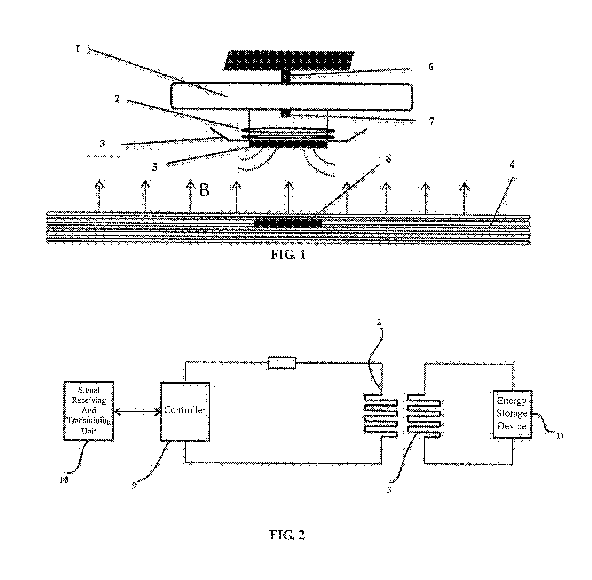
[0032] As shown in FIGS. 1 to 2, the take-off and landing control system according to the present disclosure comprises a magnet assembly provided at the side of an unmanned aerial vehicle 1 and a magnetic field assembly provided at the side of a landing platform. Particularly, the magnet assembly is a permanent magnet 5 provided on the contact surface between the undercarriage of the unmanned aerial vehicle and the landing platform. The permanent magnet 5 has a small weight and stable magnetism. The magnetic field assembly comprises an iron core provided at the landing platform and an electrified coil 2 wound around the iron core. For a magnetic field assembly provided in particular environments such as the roof of a car, the electrified coil 2 is provided in a washer to avoid the influence of bottom magnetic leakage on other articles. A magnetic field is formed at the side of the unmanned aerial vehicle when the electrified coil 2 is electrified. As the magnetic field intensity of the side of the landing platform is much larger than the magnetic field intensity of the magnetic field formed by the permanent magnet 5, the magnetic field generated by the magnetic field assembly is uniform with respect to the unmanned aerial vehicle, and the unmanned aerial vehicle will not rollover or fall.
[0033] When a forward current is supplied into the electrified coil 2, the magnetic field assembly forms a supporting magnetic field at the side of the landing platform, and generates a thrust force that acts on the unmanned aerial vehicle. In the process of take-off, a resultant force is formed by the thrust force generated by the supporting magnetic field and the lift force of the unmanned aerial vehicle, and supplements the lift force generated by the rotation of the wing, thereby reducing the energy consumption in the process of take-off of the unmanned aerial vehicle. On the other hand, in the process of landing, as the weight of the unmanned aerial vehicle itself is small, the lift force decreases rapidly when it vertically lands and the flight speed is high. In order to prevent a plane crash in landing, the thrust force acting on the unmanned aerial vehicle by the supporting magnetic field and the resistance force form a resultant force, so that the force is applied to the unmanned aerial vehicle uniformly.
[0034] In the unmanned aerial vehicle take-off and landing control system of the present embodiment, a rotational speed measuring device 6 and an infrared distance measuring device 7 are provided at the side of the unmanned aerial vehicle, and a signal receiving and transmitting module 10 and a controller 9 are provided at the side of the landing platform. The rotational speed detection signal generated by the rotational speed measuring device 6 and the distance signal generated by the infrared distance measuring device 7 are outputted to the controller 9 via the signal receiving and transmitting module 10, as two independent controlling parameters of the controller 9.
[0035] Particularly, the unmanned aerial vehicle 1 receives a take-off instruction and outputs a take-off signal, and the signal receiving and transmitting module 10 receives the take-off signal and outputs it to the controller 9. The controller 9 controls the electrified coil 2 to be supplied with a forward current. At this point the wing of the unmanned aerial vehicle 1 does not rotate. The supporting magnetic field formed by the forward current generates an upward thrust force that acts on the unmanned aerial vehicle. The forward current supplied into the electrified coil 2 is controlled by the controller 9 to continuously increase. When the upward thrust force is equal to the gravity of the unmanned aerial vehicle 1, the forward current in the electrified coil 2 reaches its maximum, and an air gap is formed between the unmanned aerial vehicle 1 and the landing platform 4, so that the unmanned aerial vehicle 1 is in a magnetic levitation state. After the air gap is formed between the unmanned aerial vehicle 1 and the landing platform 4, the infrared distance measuring device 7 generates a distance detection value of the distance between the unmanned aerial vehicle 1 and the predetermined parking location and feeds it back to the input end of the controller 9 via the signal receiving and transmitting unit 10.
[0036] After the air gap is formed between the unmanned aerial vehicle 1 and the landing platform 4, the wing of the unmanned aerial vehicle starts to rotate, and the rotational speed measuring device 6 generates a rotational speed detection value and feeds it back to the input end of the controller 9 via the signal receiving and transmitting unit 10. Optionally, when the infrared distance measuring device 7 detects that the distance detection value of the distance between the unmanned aerial vehicle 1 and the predetermined parking location is a certain value, preferably, 0.5 meter, the wing of the unmanned aerial vehicle is controlled to start to rotate, to improve the safety. After the wing of the unmanned aerial vehicle starts to rotate, the forward current supplied into the electrified coil 2 is controlled by the controller 9 to decrease with the increasing of the rotational speed of the wing of the unmanned aerial vehicle. When the rotational speed of the wing of the unmanned aerial vehicle is equal to a preset rotational speed, the current supplied into the electrified coil 2 is controlled by the controller 9 to decrease to zero. At this point, the supporting magnetic field generated at the side of the landing platform disappears, and the unmanned aerial vehicle 1 operates in the original control mode.
[0037] When the unmanned aerial vehicle 1 is preparing to land, the remote controller sends a landing instruction. The unmanned aerial vehicle 1 receives the landing instruction and outputs a landing signal, and the signal receiving and transmitting module 10 receives the landing signal and outputs it to the controller 9. The controller 9 judges whether the unmanned aerial vehicle 1 is within a landing allowable range according to the distance detection value of the distance between the unmanned aerial vehicle 1 and the landing platform 4 that is generated by the infrared distance measuring device 7. The landing allowable range refers to a particular region on the landing platform 4 that is defined with the predetermined parking location as the circle center and a particular distance as the radius. If the controller 9 determines that the unmanned aerial vehicle 1 is within the landing allowable range, the controller 9 outputs a controlling signal to keep the rotational speed of the wing of the unmanned aerial vehicle unchanged, and the electrified coil 2 is supplied with a reverse current to form an attracting magnetic field to drag the unmanned aerial vehicle 1 to right above a predetermined location. When the unmanned aerial vehicle 1 is right above the predetermined location, an infrared receiving device 8 receives an infrared signal that is emitted by an infrared distance measuring unit 7, which indicates that the unmanned aerial vehicle 1 is right above the parking location and can land, to facilitate the operating of the user who cannot see the particular location of the unmanned aerial vehicle 1. The width of the infrared receiving device 8 is slightly greater than the width of the infrared distance measuring unit 7, and a certain landing error is allowed.
[0038] Subsequently, the electrified coil 2 is controlled by the controller 9 to be supplied with a forward current which is continuously increased. Simultaneously, the rotational speed measuring device 6 continues feeding the rotational speed detection signal of the wing of the unmanned aerial vehicle 1 back to the controller 9. The forward current logarithmically increases with the passage of time. According to the characteristics of logarithmic function, when the increment speed of the intensity of the supporting magnetic field reaches its maximum, and the thrust force that acts on the unmanned aerial vehicle 1 quickly increases to compensate for the loss of the lift force in the process of landing. The increment speed of the intensity of the supporting magnetic field decreases with the passage of time, so that the thrust force that acts on the unmanned aerial vehicle reaches its maximum and is stable when it is close to the predetermined parking location. When the rotational speed of the wing of the unmanned aerial vehicle decreases to zero and the infrared distance measuring device detects that the distance between the unmanned aerial vehicle 1 and the landing platform is zero, the controller 9 controls to stop electrifying the electrified coil 2, the supporting magnetic field disappears, and the unmanned aerial vehicle 1 lands smoothly.
[0039] The control system further comprises an energy storage device 11 and a charge coil 3 that are provided in the unmanned aerial vehicle 1. The charge coil 3 is provided on the undercarriage of the unmanned aerial vehicle. When the unmanned aerial vehicle 1 is flying, the energy storage device 11 and the charge coil 3 are disconnected. When the unmanned aerial vehicle 1 is parking on the landing platform 4, the energy storage device 11 and the charge coil 3 are electrically connected, the controller 9 controls the electrified coil 2 to be supplied with a charging current, and the magnetic field assembly generates a varying charging magnetic field at the side of the landing platform. An induction current is generated in the charge coil 3 by the continuously varying magnetic field, thereby an electromotive force that meets the specification of the energy supply of the unmanned aerial vehicle 1 is obtained, and the wireless charging of the unmanned aerial vehicle 1 is realized.
[0040] In the unmanned aerial vehicle take-off and landing control system according to the above embodiment of the present disclosure, in the process of take-off or landing of the unmanned aerial vehicle, a uniform magnetic field is formed by varying the current of the electrified coil, and a thrust force that acts on the unmanned aerial vehicle is generated to supplement the lift force or resistance force in the process of take-off or landing, thereby improving the safety performance of the unmanned aerial vehicle is improved, reducing the energy consumption of the unmanned aerial vehicle when it is used, and prolonging the service life of the unmanned aerial vehicle.
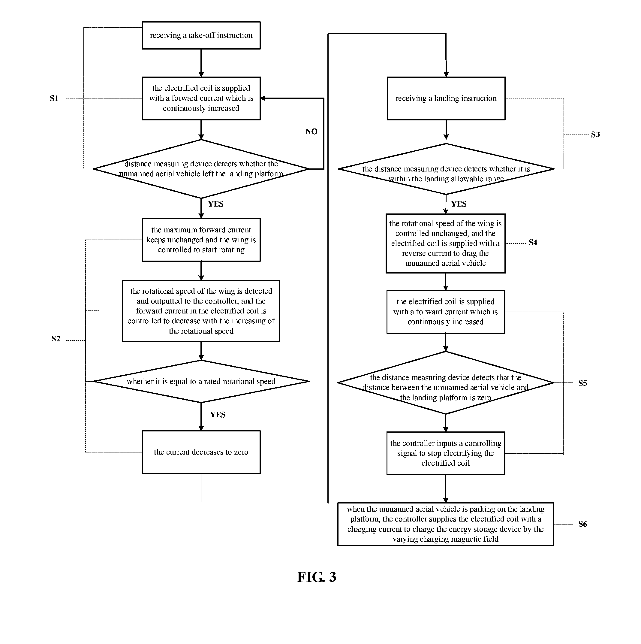
[0041] The present disclosure further provides a control method for controlling the take-off and landing of an unmanned aerial vehicle by using the unmanned aerial vehicle take-off and landing control system according to the above embodiment, particularly, as shown in FIG. 3, comprising the following steps:
[0042] S1, the controller receives the take-off instruction, controls the electrified coil to be supplied with the forward current which is continuously increased; when the thrust force that the supporting magnetic field acts on the unmanned aerial vehicle is equal to a gravity of the unmanned aerial vehicle, the forward current supplied into the electrified coil reaches its maximum, and an air gap is formed between the unmanned aerial vehicle and the landing platform.
[0043] S2, after the air gap is formed between the unmanned aerial vehicle and the landing platform, the maximum forward current supplied into the electrified coil is controlled by the controller to be unchanged, and the wing of the unmanned aerial vehicle starts to rotate; a rotational speed detection signal that is fed back by a rotational speed detecting device is inputted to an input end of the controller, and a controlling signal is outputted according to the inputted rotational speed detection signal to control the forward current supplied into the electrified coil to decrease with the increasing of the rotational speed of the wing of the unmanned aerial vehicle; when the rotational speed of the wing of the unmanned aerial vehicle is equal to a preset rotational speed, the current supplied into the electrified coil is controlled by the controller to decrease to zero.
[0044] S3, the controller receives a landing instruction, and the distance measuring device detects whether the distance between the unmanned aerial vehicle and the landing platform is within a landing allowable range.
[0045] S4, if the distance between the unmanned aerial vehicle and the landing platform is within the landing allowable range, the controller inputs a controlling signal to keep the rotational speed of the wing of the unmanned aerial vehicle unchanged, and controls the electrified coil to be supplied with a reverse current to drag the unmanned aerial vehicle to right above a predetermined parking location.
[0046] S5, the electrified coil is controlled by the controller to be supplied with a forward current which is continuously increased, to form a thrust force that acts on an unmanned aerial vehicle to supplement the loss of a resistance force caused by the decreasing of the rotational speed of the wing of the unmanned aerial vehicle; when the rotational speed of the wing of the unmanned aerial vehicle is zero and the distance measuring device detects that the distance between the unmanned aerial vehicle and the landing platform is zero, the controller inputs a controlling signal to stop electrifying the electrified coil.
[0047] S6, when the unmanned aerial vehicle is working, the energy storage device and the charge coil are disconnected; when the unmanned aerial vehicle is parking on the landing platform, the controller outputs a controlling signal, and controls the electrified coil to be supplied with a charging current, the magnetic field assembly generates a varying charging magnetic field at the side of the landing platform, and the energy storage device and the charge coil are connected to charge the energy storage device.
[0048] The control method according to the present disclosure reduces the energy consumption of the unmanned aerial vehicle in process of take-off or landing, improves the safety performance of the unmanned aerial vehicle, and has the merit of good operability.
[0049] Finally, it should be noted that the above embodiments are merely intended to describe the technical solutions of the present disclosure, rather than limiting them. Although the present disclosure is described in detail by referring to the above embodiments, a person skilled in the art should understand that the technical solutions disclosed by the above embodiments can be amended, and some parts of their technical features can be equivalently replaced, and these amendments or replacements do not deviate from the spirit and scope of the present disclosure.
* * * * *
D00000
D00001
D00002
XML
uspto.report is an independent third-party trademark research tool that is not affiliated, endorsed, or sponsored by the United States Patent and Trademark Office (USPTO) or any other governmental organization. The information provided by uspto.report is based on publicly available data at the time of writing and is intended for informational purposes only.
While we strive to provide accurate and up-to-date information, we do not guarantee the accuracy, completeness, reliability, or suitability of the information displayed on this site. The use of this site is at your own risk. Any reliance you place on such information is therefore strictly at your own risk.
All official trademark data, including owner information, should be verified by visiting the official USPTO website at www.uspto.gov. This site is not intended to replace professional legal advice and should not be used as a substitute for consulting with a legal professional who is knowledgeable about trademark law.