Method For Producing Wall Parts Of A Housing For Pressure Vessels
KLOFT; Peter ; et al.
U.S. patent application number 16/065879 was filed with the patent office on 2019-01-10 for method for producing wall parts of a housing for pressure vessels. The applicant listed for this patent is HYDAC TECHNOLOGY GMBH. Invention is credited to Herbert BALTES, Peter KLOFT.
| Application Number | 20190009335 16/065879 |
| Document ID | / |
| Family ID | 56292656 |
| Filed Date | 2019-01-10 |

| United States Patent Application | 20190009335 |
| Kind Code | A1 |
| KLOFT; Peter ; et al. | January 10, 2019 |
METHOD FOR PRODUCING WALL PARTS OF A HOUSING FOR PRESSURE VESSELS
Abstract
The invention relates to a method for producing wall parts (24) of a housing for pressure vessels by means of a 3-D printing method, wherein material is applied layer-by-layer in order to form each wall part (24). Said method is characterized in that, in case of wall part geometries (28) that lead to distortions (44) that impede the application of material, the layer thickness in the application of material must be selected in such a way that the particular distortion (44) is avoided and that the formation of wall part geometries (28) that are critical in this respect is performed without support parts.
| Inventors: | KLOFT; Peter; (Ransbach-Baumbach, DE) ; BALTES; Herbert; (Losheim, DE) | ||||||||||
| Applicant: |
|
||||||||||
|---|---|---|---|---|---|---|---|---|---|---|---|
| Family ID: | 56292656 | ||||||||||
| Appl. No.: | 16/065879 | ||||||||||
| Filed: | June 18, 2016 | ||||||||||
| PCT Filed: | June 18, 2016 | ||||||||||
| PCT NO: | PCT/EP2016/001042 | ||||||||||
| 371 Date: | June 25, 2018 |
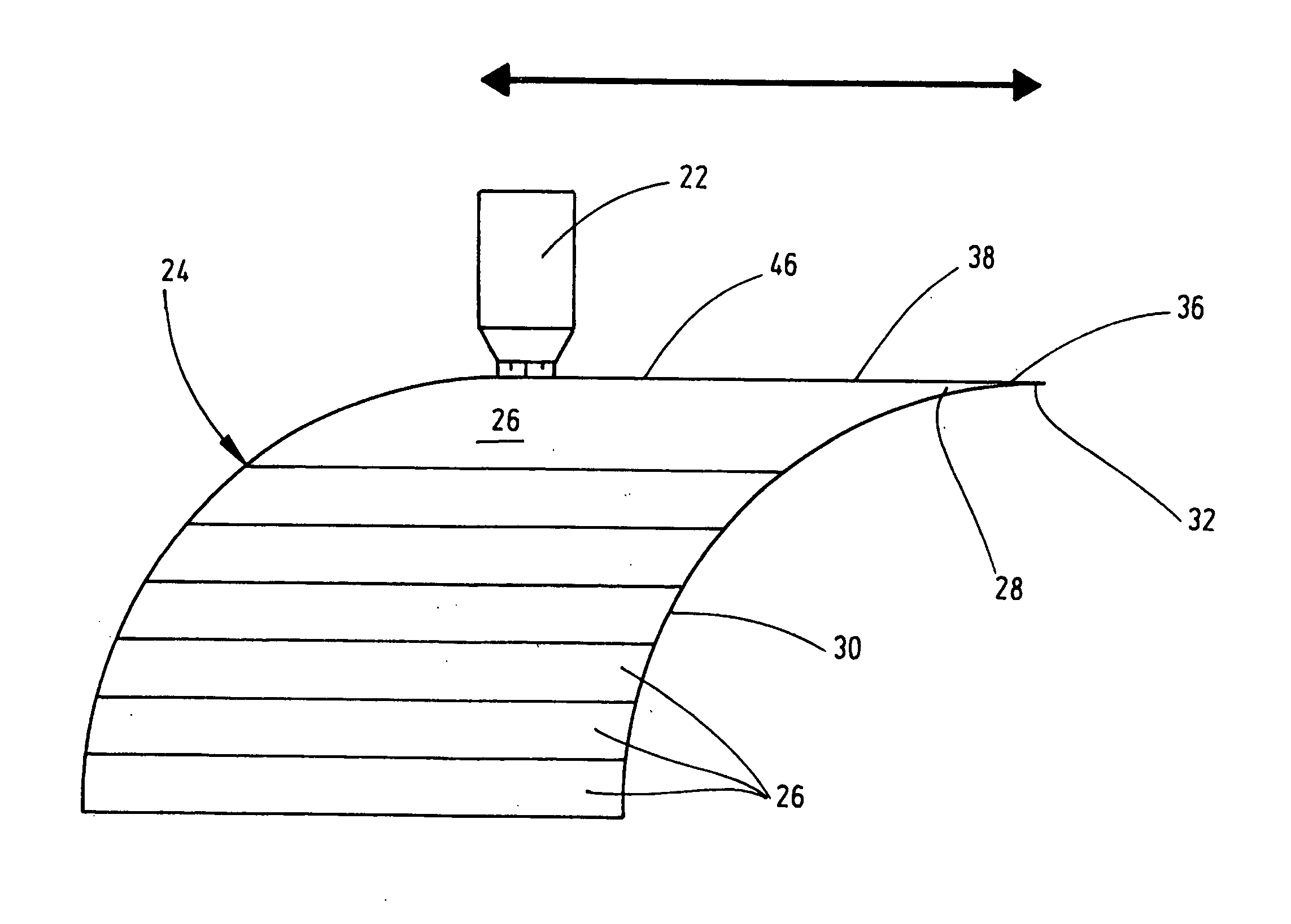
| Current U.S. Class: | 1/1 |
| Current CPC Class: | F15B 2201/605 20130101; B22F 2003/1057 20130101; F15B 2201/4056 20130101; Y02P 10/25 20151101; B23K 15/0086 20130101; B22F 3/1055 20130101; F17C 1/16 20130101; F15B 2201/405 20130101; B33Y 10/00 20141201; F15B 1/106 20130101; F17C 2203/066 20130101; F17C 2209/00 20130101; F17C 1/00 20130101; F17C 1/14 20130101; F17C 2203/0636 20130101; F17C 2209/2109 20130101; B22F 5/10 20130101; B33Y 80/00 20141201; F17C 2270/0554 20130101 |
| International Class: | B22F 3/105 20060101 B22F003/105; B33Y 10/00 20060101 B33Y010/00; B33Y 80/00 20060101 B33Y080/00; F17C 1/00 20060101 F17C001/00; B23K 15/00 20060101 B23K015/00 |
Foreign Application Data
| Date | Code | Application Number |
|---|---|---|
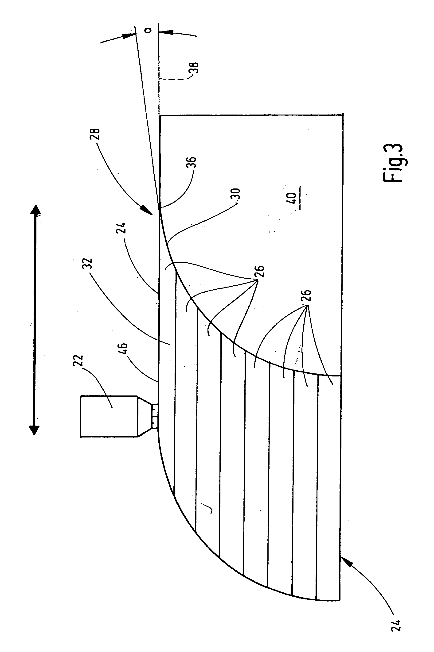
| Dec 31, 2015 | DE | 10 2015 017 026.0 |
Claims
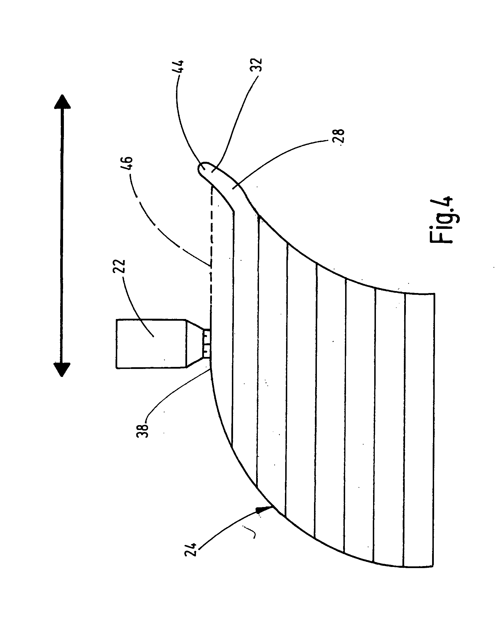
1. A method for producing wall parts (24) of a housing (10) for pressure vessels by means of a 3D printing method, wherein material is applied layer-by-layer to form each wall part (24), characterized in that in the case of wall part geometries (28), which result in warping (44) which prevents the material application, the layer thickness for the material application is selected sufficiently large that the respective warping (44) is prevented and that the formation of to this extent critical wall part geometries (28) is realized free of support parts (40).
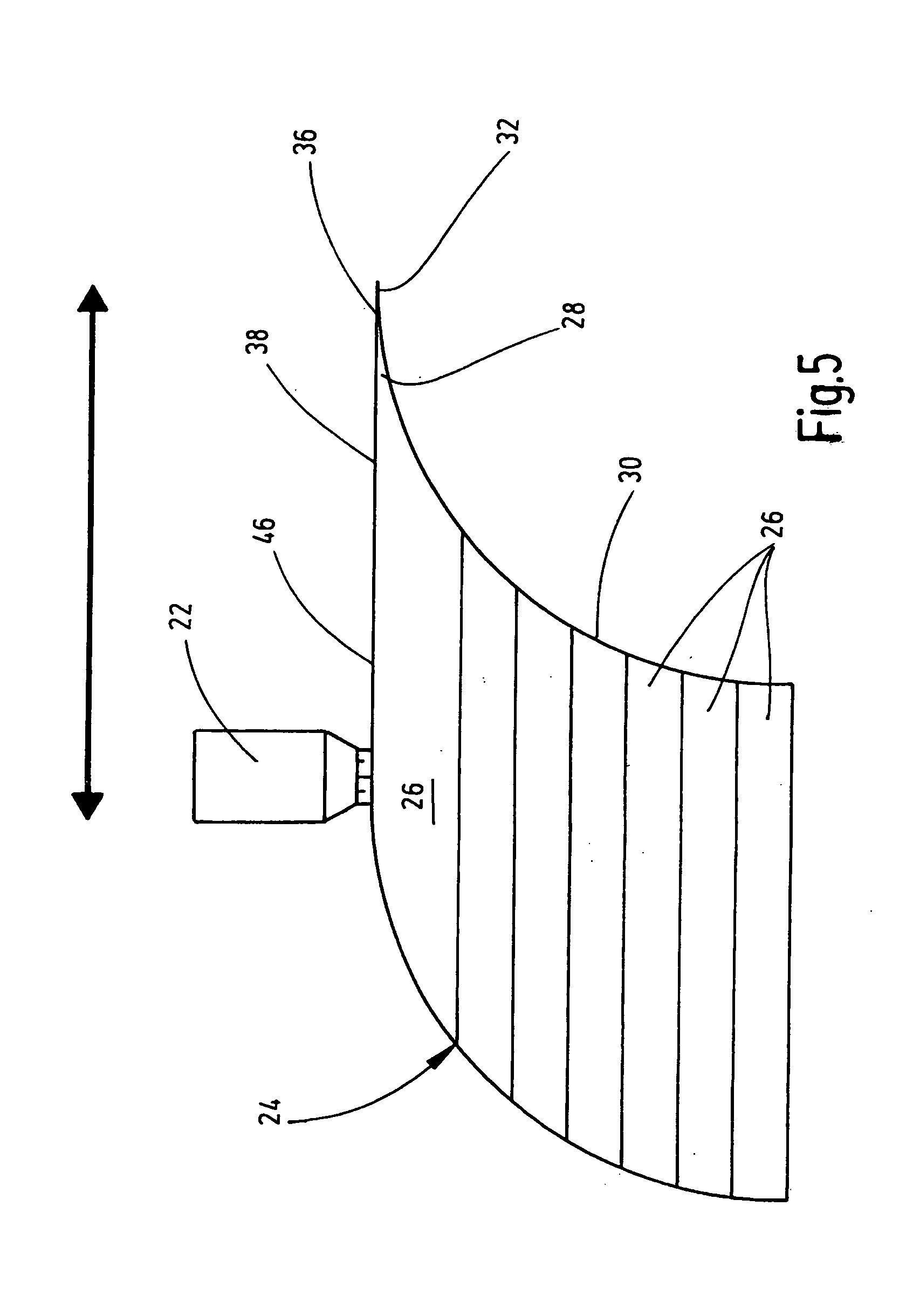
2. The method according to claim 1, characterized in that the critical wall part geometry (28) during construction of the housing (10) is formed from a layer (32) projecting in a pointed or thin-walled manner in the direction of an inner wall (30) of same, the layer thickness of which along the material application plane (38) is selected larger than the previous layers in the construction of the housing (10) with non-critical wall part geometry.
3. The method according to claim 1, characterized in that the respective pointed or thin-walled projecting layer (32) of the critical wall part geometry (28) with its layer (32) in the region of the projection encloses an overhang angle (a) relative to the material application plane (38) of less than 30.degree., preferably of less than 15.degree., particularly preferably of less than 5.degree..
4. The method according to claim 1, characterized in that the respective warping (44) to be avoided in critical wall part geometries (28) is formed by hardened material parts, which project in the direction of the continuous, layer-by-layer material build-up on the application side (46) and which constitute a collision hazard for a material application tool (22), which is used for the respective 3D printing method.
5. The method according to claim 1, characterized in that the wall parts (24) on the inner side (30) of the finished housing (10) form a spheroid, preferably in the form of a sphere.
6. The method according to claim 1, characterized in that it is applied in the top third, preferably in the top sixth, in particular before closure of the spheroid.
7. The method according to claim 1, characterized in that with the contacting of the adjacent wall parts (24) with completion of the spheroid on the inner wall side (30) of the housing (10) the layer application takes place with a layer thickness as is selected at the start of the material removal process with formation of the wall parts (24).
8. The method according to claim 1, characterized in that but for the region of at least one potential media connection point (14) and/or at least one potentially present reinforcement part (18), which is preferably arranged in the equatorial region (20) of the spheroid on the outer wall of the housing (10), the material thickness of the housing (10) is uniformly realized by means of the material application.
9. The method according to claim 1, characterized in that as a 3D printing method selective laser sintering, or electron beam melting is used, and in that the metal powder used for this is selected from the materials steel, stainless steel, aluminum, titanium, nickel, etc. and mixtures thereof.
10. A pressure housing, in particular envisaged for a pressure vessel in the form of a Helmholtz resonator, an air chamber or a hydraulic accumulator, produced with a method according to claim 1, characterized in that in a region above the equator (20), in particular in a top polar cap region (34) of a spheroid formed from the inner wall (30) of the housing (10), preferably in a spherical shape, the material roughness of the inner wall (30) before any remachining is greater than in the region below the equator (20), in particular in the direction of a bottom polar cap region (42), which is passed through by a media connection point (14).
11. The pressure housing according to claim 10, characterized in that it is formed from one piece.
Description
[0001] The invention relates to a method for producing wall parts of a housing for pressure vessels by means of a 3D printing method, wherein material is applied layer-by-layer to form each wall part.
[0002] Pressure vessels are commonly understood to be essentially closed vessels, the internal pressure of which is higher than the ambient pressure. Pressure vessels commonly include storage vessels for gases and compressed air vessels and silos with compressed air application as well as pressure storage vessels such as hydraulic accumulators, membrane extension vessels, air chambers, Helmholtz resonators, etc. According to the European legislation on free movement of goods, there is considered to be a difference between simple pressure vessels according to directive 2009/105/EC and so-called pressure devices according to the pressure devices directive 97/23/EC.
[0003] Hydraulic accumulators, which are also referred to as hydro accumulators in technical parlance, essentially serve to store pressure energy. In the case of the weight- and spring-loaded, mechanical hydraulic accumulators, this occurs by means of a change of potential energy, whereas the gas-loaded accumulators change the internal energy of a working gas. Depending on the design of their separating element with which different fluids can be separated from one another inside the accumulator housing, there is differentiation between membrane accumulators, piston accumulators, bladder accumulators and bellows accumulators. The operation of these accumulators is essentially based on utilizing the compressibility of a gas for fluid accumulation. Nitrogen is commonly used as the energy medium. If the hydraulic accumulator has no separating element, it is usually an air chamber construction which is known per se. In recent times such pressure accumulators and their housings have also been used as Helmholtz resonators in order to dampen or to smooth pulsing fluid vibrations which occur in particular in hydraulic circuits and which can have a damaging effect on hydraulic circuit-connected components, such as for example valve assemblies, hydraulic working cylinders, pressure monitoring devices and control devices, etc. In this way any sounds which may occur even during operation of the hydraulic circuit and which are disruptive are acoustically dampened.
[0004] The above-mentioned pressure vessels including the Helmholtz resonators and any separating elements thereof can be produced in a number of ways. In addition to a machining formation for the respective accumulator housing, it may also be obtained by means of casting. Pressure vessels which are produced using the so-called composite construction are also used in order to thus obtain at the same time as low material input costs a low construction weight together with high structural strength for the accumulator. Thus document DE 10 2014 008 649 A1 discloses a method for producing such a pressure vessel, preferably in the form of a bladder accumulator, in which firstly a supporting structure, in particular in the form of a liner, is provided, to which a fiber material is applied to form a base structure which, in turn introduced into a heatable molding device, permits the introduction of a matrix between the molding device and the base structure, which at least partially penetrates the fiber material and, appropriately hardened after removal of the accumulator housing, produces a bladder accumulator.
[0005] This in principle very advantageous method, which leads to accumulator housings with high compressive strength with a particularly low construction weight, is disadvantageous to the extent that for each accumulator type a separate molding device has to be created, which thus increases the production costs considerably. The hardening of the matrix in the heatable form also requires production time, in addition to the energy costs for the mold heating, in spite of the relatively short reaction times of a reactive resin system for the matrix. In addition, the manual cost for the handling of the molding device should not be underestimated.
[0006] The priority-establishing document DE 10 2015 017 026 by the same property right proprietor already proposed as an alternative production method for pressure vessels to the above-described production method the production of pressure vessels and potentially the parts thereof at least partially by means of a 3D printing method, so that machining work or a molding device such as a molding tool to be heated can be entirely dispensed with. Instead the accumulator housing of a pressure vessel together with its wall parts or components of such pressure vessels, such as separating elements, can be produced in a molding tool-free manner, which also helps to significantly reduce the manual costs during production. The technical term pressure vessel is to be understood in a broad sense here and includes for example liner constructions, which are subsequently reinforced preferably with fiber fabrics (composites) or solutions which can be used as Helmholtz resonators.
[0007] By means of the afore-mentioned 3D printing method almost all forms of pressure vessels and pressure accumulators can be realized, and in fact in a free forming manner so that a number of design options can be realized, with an accumulator housing thus being able to be relatively freely adapted in a direct manner even to specific installation conditions in situ, so that it is not always necessary to resort to symmetrical accumulator housings of pressure vessels.
[0008] In practical implementation of the method for producing wall parts of a housing for pressure vessels by means of a 3D printing method, wherein material is applied layer-by-layer to form each wall part, it has however been found that in particular in the case of wall part geometries which seem complicated, with which in particular the so-called overhang angle relative to the respective material application plane by means of the 3D printer becomes too steep, material warping occurs which prevents the material application of the printer.
[0009] In a known manner a 3D printer cannot print "in air", so that it is common for support part materials to be used in the case of self-supporting, projecting or forwards hanging elements, in particular with a large overhang angle, which the 3D printer preferably applies at the same time with a separate application nozzle during the pressure operation for the creation of the actual workpiece, here in the form of the housing for pressure vessels. However there are also soluble support materials, which as a separate component can help to support the 3D printing structure to be created and which in the dissolved state can be removed again from the structure. It surely goes without saying at this point that said application and the removal of support material in the context of the 3D printing method is associated with a corresponding time and cost outlay, which negatively affects the production time in the 3D printing method. The dissolved support parts can also constitute an environmental problem when disposed of.
[0010] However, if such support parts or support structures are dispensed with in the case of sufficiently large overhang angles, in particular in the case of the use of plastic materials as printing material it may be the case that it drips downwards in the direction of the overhang and destroys the desired print structure. This likewise applies in the event that warping occurs on the top side of the material application, for example bubble formation or burr formation. In the case of a metal material application, in the region of the free end of the respective last applied layer in the direction of the overhang, solid, projecting, annular warping may occur due to material stress during hardening, which in the hardened state then creates a collision hazard for the application nozzle of the 3D printer to be moved, which in the subsequent layer application comes into direct contact with the warping of the wall part geometry. In addition to the destruction of the wall part geometry, the destruction of the application nozzle of the 3D printer must also be expected.
[0011] On this basis, the invention addresses the problem of providing an improved 3D printing method, with which in a cost-efficient manner and with reduced time outlay even the production of complex wall part geometries for pressure vessels of any type whatsoever is possible, which in the manner outlined above tends to results in warping due to the material usage. This problem is solved by a method having the features of Claim 1 in its entirety.
[0012] Because, according to the characterizing part of claim 1, with wall part geometries of the housing which lead to warping which prevents the material application, the layer thickness for the material application is selected large enough that the respective warping is avoided and that the formation of to this extent critical wall part geometries is realized free of support parts, in a surprising manner it is possible for the average person skilled in the art of 3D printing methods, by means of targeted layer-by-layer material application which is to be hardened, with respect to the layer thickness, to design the 3D printing method in terms of the operational sequence such that the warping during hardening of the material which prevents the 3D material application by means of the application nozzle cannot take place at all. In a particularly advantageous manner this occurs in a support-free manner, so that the support parts must not be produced in a costly manner nor must they then also be removed. In particular in the case of wall parts to be created, which include cavities such as spheroids, a complete or residue-free removal of the support part material cannot always be guaranteed, so that the production method according to the invention has particular application here.
[0013] Because in order to avoid the warping the layer thickness in the material application is selected suitably large, and is for example twice or five times the previous thin-layered application, the material behavior in the thickened layer is homogenized and has minimal stress or is stress-free and the occurrence of the respective material stress which generates warping, in particular during the cooling process or hardening process, is avoided in a support part-free manner.
[0014] Depending on the complex wall part geometries to be created it can be envisaged that, in addition to an initially thin layer application in the critical warping zone in multiple layer arrangement one on top of the other the thick layer application is selected, which in turn in the transition towards wall part geometries which must not be critically created is again reduced, which assists with the compact and pressure-resistant construction of the pressure vessel housing as a whole which is to be constructed.
[0015] Additional advantageous embodiments of the method according to the invention and the pressure vessels which can be produced according to this method are the subject of the other dependent claims.
[0016] The method according to the invention will be explained in greater detail below with reference to the production of a pressure vessel, in particular in the form of a Helmholtz vessel. The drawings show in schematic and not to scale depictions:
[0017] FIGS. 1 and 2 once in a sectional depiction and once in a top view an exemplary embodiment of a pressure vessel in the form of an air chamber or Helmholt resonator;
[0018] FIGS. 3 to 5 in an enlarged depiction, a cutout circle identified in FIG. 1 by an X, with FIGS. 3 and 4 presenting method solutions according to the prior art and FIG. 5 relating to the method solution according to the invention.
[0019] As 3D printing methods for producing pressure vessels and the parts thereof, sinter- and powder printing methods, stereolithography and printing with liquid components are in principle suitable. All of the above-mentioned 3D printing methods are also frequently used in so-called rapid prototyping.
[0020] When objects such as accumulator housings are to be constructed exclusively from metal, the so-called electron beam melting has proven to be suitable as a 3D printing method. In electron beam melting metal powder is melted in layers and machined as a housing wall. Likewise suitable is selective laser melting, in which a metal powder is melted locally only. The use of selective laser sintering is equally possible, in which a metal powder is heated with a laser for a short time such that it melts, and it then solidifies again with formation of the metal accumulator housing. All of the above-mentioned 3D printing methods belong to the category of sintering- and powder printing methods.
[0021] When the pressure vessel is to be printed using plastic materials, printing with liquid plastic materials is an option. In particular multi jet modeling has proven to be successful, which in terms of its essential construction is very like conventional inkjet printing. In this 3D printing method liquid plastic material is applied from a nozzle, which can preferably move in several directions, and as soon as the material emerges from the nozzle in a forming manner it is appropriately hardened under an energy source, for example in the form of UV light.
[0022] With the multi-jet modeling plastic materials in droplet form with dimensions of a few picoliters are discharged, with the spraying of the droplets preferably occurring in a computer-controlled manner with a high clock frequency of for example 2 kHz. Liquefied acrylates have proven to be particularly suitable plastic materials, the viscosity of which can be adjusted as desired by the addition of a reactive thinner. The hardenability with UV radiation is preferably promoted by the addition of a photoinitiator. In one example of a housing material the plastic material contains as an acrylate material 90% Epecryl 4835, a prepolymer produced by the company UCB, 8% HDDA (company UCB) as reactive thinner for viscosity adjustment and 2% Darocur 1173, produced by the company Ciba-Geigy, as a photoinitiator.
[0023] In another example, as housing material acrylate materials 90% Epecryl 4835 and 4% Epecryl 230 by the company UCB are envisaged. As reactive thinner 4% HDDA by the company UCB and as photoinitiator 2% Darocur 1173 by the company Ciba-Geigy are contained in the material for the material removal or application.
[0024] With the above plastic materials described in detail or other suitable plastic materials accumulator housings 10 can be constructed in the 3D printing method, as presented by way of an example for a pressure vessel 12 in the form of an air chamber or a Helmholtz resonator for pulsation dampening of fluids including gases according to the depictions in FIGS. 1 and 2. A fluid connection point 14 is integrally mounted on the accumulator housing 10 at the bottom 1 end with a special connection geometry for the purpose of connection of the pressure vessel 12 in a conventional manner to a fluid supply circuit, in particular a gas supply circuit. The accumulator housing 10 on the inside essentially forms a spherical cross section, into which the fluid connection point 14 enters in a media-conducting manner via a central channel 16. The accumulator housing 10 has an essentially constant wall diameter; but it is provided in the center with a corresponding annular reinforcement 18 in the equatorial region 20.
[0025] Such pressure vessels 12 can also be printed by means of a metal powder and are then entirely pressure resistant up to 350 bar in this embodiment, with regular operating or working temperatures of 40.degree. C. to 150.degree. C. The pressure vessel presented here is preferably constructed from a metal material, namely titanium Ti5Al64V. In addition to the terms already mentioned, such pressure vessels are also referred to in technical parlance as silencers.
[0026] Viewed in the viewing direction of FIGS. 1 and 2 the metal 3D printing material construction begins from the bottom end, in other words, beginning at the free end of the fluid connection point 14. With only one 3D printing production device with one or more application nozzles 22 (cf. FIGS. 3 to 5) such a pressure vessel 12 can be produced in all sizes, even with changed internal cross section forms, for example as an oval or polygonal spheroid, and various connection points (not depicted).
[0027] As disclosed in document DE 10 2015 017 026, with such 3D printing methods other types of accumulators can also be produced, which have corresponding separating elements in the accumulator, such as membranes, bladders, pistons, etc., which can preferably be printed together with the accumulator housing in one work process (not depicted).
[0028] The following text will now describe in detail with reference to FIGS. 3 to 5, how an accumulator housing construction according to FIGS. 1 and 2 is obtained with a 3D printing method. Because the pressure vessel 12 depicted in FIGS. 1 and 2 does not always serve only to "store" fluids or other media, in the context of the application the terms accumulator housing 10 and housing 10 are used synonymously.
[0029] In order to produce each wall part 24 for the housing 10 a uniform material application takes place in layers 26 by means of the material application nozzle 22 of the 3D printing device which is otherwise not depicted in detail. The applied material is a titanium material, which is particularly suitable for 3D printing. For the layer-by-layer material removal, the nozzle 22 moves in the depicted horizontal double arrow direction. The respective nozzle 22 can however also be moved in any other planes, and in particular it is moved for the layer-by-layer material build-up by one layer thickness in the axial direction continuously vertically upwards, until the housing 10 is completely produced.
[0030] The material application shown in FIG. 3 contains a so-called critical wall part geometry 28, which is obtained in construction of the housing 10 from a layer 32 projecting in a pointed manner or a thin-walled manner in the direction of an inner wall 30 of same. Such critical wall part geometries 28 are in particular produced when, as depicted in circle X in FIG. 1, the accumulator 10 is completed in the direction of the top polar cap region 34. The respective layer 32 projecting in a pointed manner or a thin-walled manner of the critical wall part geometry 28 forms with its layer 36 in the region of the projection 36 a notional overhang angle a relative to the material application plane 38 of approximately 8.degree.. If in accordance with the depiction of FIG. 3 the layer-by-layer construction of the projection 36 and thus the critical wall part geometry 28 of the inner wall 30 is now in a conventional manner supported by a support part body 40, a homogeneous layer construction is produced, including for the topmost layer 32, by means of the application nozzle 22.
[0031] A comparison of FIG. 3 with FIG. 1 clearly shows that such support part bodies 40, which are simultaneously generated by means of their own application nozzle (not depicted) during the actual 3D printing method by the production machine, cannot be easily removed due to the narrowness of the channel 16 from the spherical interior as a spheroid of the accumulator 10. Even in the case of chemical dissolving of the support part body 40 residue remains on the inner wall 30 of the housing 10, which has a damaging impact on subsequent use, in particular in the context of a use as a Helmholtz resonator. The residue also reduces the useable volume of the pressure accumulator or housing 10. The removal of comparable support parts or support part bodies (not depicted) at the external circumference of the housing 10, in other words at the outer wall in the bottom polar cap region 42 of the housing 10, is not critical by comparison, because they can be easily removed from the outer wall. Irrespective thereof, the mounting of such support parts or support part bodies is however of course associated with production costs, which would preferably be dispensed with.
[0032] If the support part body 40 is simply omitted according to the depiction of FIG. 4, due to material stress, in particular during cooling, an upwards projecting material warping 44 often appears on the inner wall side of the housing 10, in particular when a metal material application takes place, and as soon as this warping 44 to be avoided, formed from the projection 36, is hardened, it forms projecting on the application side 46 of the nozzle 22 a collision hazard for this material application tool 22, which in the case of the collision can lead to its destruction and to the destruction of the sought wall part geometry 28.
[0033] It is now surprising for the average person skilled in the art of production of housings and accumulator housings using 3D printing methods, that he can avoid such projecting warping 44 on the application side 46 of the material application if he, in accordance with the schematic depiction of FIG. 5, enlarges the last applied layer in terms of the layer thickness such that the warping 44 no longer occurs, which is associated with the largely stress-free material cooling behavior of the metal application material. Preferably, the material application in the region of the critical wall part geometry 28 is selected larger by the factor 1.5 to 5 compared with a conventional layer thickness, with the enlarged layer thickness being selected depending on the critical wall part geometry 28 to be formed such that the warping 44 commonly in the form of a closed protrusion ring does not occur during printing. This makes it possible to also produce critical wall part geometries on the outer side of the accumulator 10, as increasingly occur in the bottom polar cap region 42, from the outer wall side in a warping-free and support part-free manner.
[0034] It has been demonstrated that with a thus produced accumulator or pressure housing 10 in particular in the top polar cap region 34 with the critical wall part geometries 28 due to the enlarged layer thickness a certain amount of material roughness occurs on the inner wall 30 of the housing 10. If one leaves the material roughness on said inner wall side of the accumulator 10, this proves to be advantageous for obtaining an improved vibration damping, because the projecting material parts of the material roughness help to prevent sound reflection and divert it into the wall structure of the housing 10.
[0035] The housing 10 produced using 3D printing can also be formed as a liner, which can be wrapped in a fiber fabric (not depicted) for the purpose of completion and reinforcement. As a separating element, for example in the form of a metal bellows membrane, it can also be produced using the 3D printing method together with the production of the accumulator housing 10.
* * * * *
D00000
D00001
D00002
D00003
D00004
XML
uspto.report is an independent third-party trademark research tool that is not affiliated, endorsed, or sponsored by the United States Patent and Trademark Office (USPTO) or any other governmental organization. The information provided by uspto.report is based on publicly available data at the time of writing and is intended for informational purposes only.
While we strive to provide accurate and up-to-date information, we do not guarantee the accuracy, completeness, reliability, or suitability of the information displayed on this site. The use of this site is at your own risk. Any reliance you place on such information is therefore strictly at your own risk.
All official trademark data, including owner information, should be verified by visiting the official USPTO website at www.uspto.gov. This site is not intended to replace professional legal advice and should not be used as a substitute for consulting with a legal professional who is knowledgeable about trademark law.