Device And Method For Preparing Large-sized High-quality Aluminium Alloy Ingot
ZHANG; Zhifeng ; et al.
U.S. patent application number 16/067306 was filed with the patent office on 2019-01-10 for device and method for preparing large-sized high-quality aluminium alloy ingot. This patent application is currently assigned to GENERAL RESEARCH INSTITUTE FOR NONFERROUS METALS. The applicant listed for this patent is GENERAL RESEARCH INSTITUTE FOR NONFERROUS METALS. Invention is credited to Yuelong BAI, Mingwei GAO, Jianchao LIU, Jun XU, Yujie YANG, Shaoming ZHANG, Zhifeng ZHANG.
| Application Number | 20190009328 16/067306 |
| Document ID | / |
| Family ID | 59224516 |
| Filed Date | 2019-01-10 |


| United States Patent Application | 20190009328 |
| Kind Code | A1 |
| ZHANG; Zhifeng ; et al. | January 10, 2019 |
DEVICE AND METHOD FOR PREPARING LARGE-SIZED HIGH-QUALITY ALUMINIUM ALLOY INGOT
Abstract
Provided is a device for preparing a large-sized high-quality aluminium alloy ingot, which is mainly composed of a uniform cooler, a hot top, an oil-gas lubrication mold, an induction coil and a dummy ingot, wherein the hot top is arranged above the oil-gas lubrication mold, the induction coil is arranged outside the oil-gas lubrication mold, the uniform cooler is arranged inside the oil-gas lubrication mold, and the dummy ingot is arranged below the oil-gas lubrication mold. Further provided is a method for preparing a large-sized high-quality aluminium alloy ingot. The device combines a partitioned gas supply mold with the uniform cooler and an electromagnetic stirrer, and the effective coupling of the three achieves forced and uniform solidification forming of a melt under gas pressure contact conditions, such that a stable and continuous gas film is formed between the melt and the mold. The ingot has a smooth surface, and a fine and uniform internal structure.
| Inventors: | ZHANG; Zhifeng; (Beijing, CN) ; XU; Jun; (Beijing, CN) ; ZHANG; Shaoming; (Beijing, CN) ; BAI; Yuelong; (Beijing, CN) ; GAO; Mingwei; (Beijing, CN) ; LIU; Jianchao; (Beijing, CN) ; YANG; Yujie; (Beijing, CN) | ||||||||||
| Applicant: |
|
||||||||||
|---|---|---|---|---|---|---|---|---|---|---|---|
| Assignee: | GENERAL RESEARCH INSTITUTE FOR
NONFERROUS METALS Beijing CN |
||||||||||
| Family ID: | 59224516 | ||||||||||
| Appl. No.: | 16/067306 | ||||||||||
| Filed: | June 15, 2016 | ||||||||||
| PCT Filed: | June 15, 2016 | ||||||||||
| PCT NO: | PCT/CN2016/085826 | ||||||||||
| 371 Date: | June 29, 2018 |
| Current U.S. Class: | 1/1 |
| Current CPC Class: | B22D 11/07 20130101; B22D 11/112 20130101; B22D 11/0401 20130101; B22D 11/049 20130101; B22D 11/115 20130101; B22D 11/114 20130101 |
| International Class: | B22D 11/07 20060101 B22D011/07; B22D 11/112 20060101 B22D011/112; B22D 11/115 20060101 B22D011/115 |
Foreign Application Data
| Date | Code | Application Number |
|---|---|---|
| Dec 30, 2015 | CN | 201511020092.0 |
| Dec 30, 2015 | CN | 201521131860.5 |
Claims
1. A device for preparing a large-sized high-quality aluminium alloy ingot, comprising: a uniform cooler; a hot top; an oil-gas lubrication mold; an induction coil; and a dummy ingot, wherein the hot top is arranged above the oil-gas lubrication mold, the induction coil is arranged outside the oil-gas lubrication mold, the uniform cooler is arranged inside the oil-gas lubrication mold, and the dummy ingot is arranged below the oil-gas lubrication mold.
2. The device for preparing a large-sized high-quality aluminium alloy ingot according to claim 1, wherein the oil-gas lubrication mold comprises a mold body and a graphite ring mounted above the mold body, wherein the graphite ring is provided with a gas groove and an oil groove on its outer wall, and wherein the oil groove is separated from the gas groove, and is arranged on an upper portion thereof.
3. The device for preparing a large-sized high-quality aluminium alloy ingot according to claim 2, wherein the gas groove is divided into 3-20 sections for independent gas supply and control.
4. The device for preparing a large-sized high-quality aluminium alloy ingot according to claim 3, wherein each section of the gas groove has a length of 100-500 mm.
5. The device for preparing a large-sized high-quality aluminium alloy ingot according to claim 2, wherein the graphite ring is made of porous graphite.
6. The device for preparing a large-sized high-quality aluminium alloy ingot according to claim 2, wherein the mold body is provided with upper and lower rows of water spraying holes, and wherein the upper row of water spraying holes forms an angle of 15-30 degrees with respect to a wall of the mold, and has a diameter of 1-5 mm; while the lower row of water spraying holes forms an angle of 0-25 degrees with respect to the wall of the mold, and has a diameter of 2-8 mm.
7. The device for preparing a large-sized high-quality aluminium alloy ingot according to claim 6, wherein water volumes of the upper and lower rows of water spraying holes are independently controlled, and the diameter of the upper row of water spraying holes is smaller than or equal to that of the lower row of water spraying holes.
8. The device for preparing a large-sized high-quality aluminium alloy ingot according to claim 1, wherein a magnet yoke of the induction coil is of a telescopic design, and is retractable in a range of 0-100 mm, and wherein the induction coil generates an electromagnetic field which is guided into a melt inside the mold via the magnet yoke.
9. The device for preparing a large-sized high-quality aluminium alloy ingot according to claim 8, wherein the induction coil generates a rotating electromagnetic field, a traveling wave electromagnetic field or a compound electromagnetic field.
10. The device for preparing a large-sized high-quality aluminium alloy ingot according to claim 1, wherein an upper portion of the uniform cooler is a heat insulation end, and a lower portion is a cooling end, wherein the heat insulation end is provided with a stirring blade.
11. The device for preparing a large-sized high-quality aluminium alloy ingot according to claim 10, wherein the heat insulation end is of a cylindrical shape, and is made of high temperature-resistant heat insulation ceramic material.
12. The device for preparing a large-sized high-quality aluminium alloy ingot according to claim 11, wherein the heat insulation end has an outer diameter of 100-800 mm.
13. The device for preparing a large-sized high-quality aluminium alloy ingot according to claim 10, wherein the cooling end is made of thermally conductive material.
14. The device for preparing a large-sized high-quality aluminium alloy ingot according to claim 13, wherein the cooling end is of a spiral shape, and is made of graphite, copper, molybdenum, titanium or composite materials thereof.
15. The device for preparing a large-sized high-quality aluminium alloy ingot according to claim 10, wherein the stirring blade is made of high temperature-resistant material, and is arranged to be 0-8 in number.
16. The device for preparing a large-sized high-quality aluminium alloy ingot according to claim 15, wherein the stirring blade is made of copper, molybdenum, titanium, ceramic or composite materials thereof, and has a width of 10-100 mm and a thickness of 2-8 mm.
17. The device for preparing a large-sized high-quality aluminium alloy ingot according to claim 1, wherein the uniform cooler is one or more in number, which is arranged to a height where the mold is located, and has a rotational speed of 0-300 r/min.
18. The device for preparing a large-sized high-quality aluminium alloy ingot according to claim 17, wherein a cooling medium employed by the uniform cooler is air, nitrogen, water or oil, and the flow of the cooling medium is 0-2000 L/min.
19. A method for preparing a large-sized high-quality aluminium alloy ingot, the method comprising the steps of: pouring a melt that has been refined and stabilized to be 80-100 degrees Celsius higher than the liquidus temperature into a hot top during the semi-continuous casting operation; introducing air and lubricating oil into a gas groove and an oil groove arranged on an outer wall of a graphite ring; controlling flows of upper and lower water spraying holes; an alloy melt reaches an upper portion of a dummy ingot through the hot top and a mold, and a liquid surface of the melt is elevated; after the continuous casting operation is initiated, the dummy ingot descends slowly, and increasing a flow of cooling water slowly; and after the casting process is stabilized, applying uniform cooling and electromagnetic applied to obtain a large-sized high-quality aluminium alloy ingot in the end.
20. The method for preparing a large-sized high-quality aluminium alloy ingot according to claim 19, wherein the flow of air in the gas groove is 500-5000 mL/min, while the oil groove supplies oil in a pulsed manner, and has an oil supplying capacity of 60-100/s.
21. The method for preparing a large-sized high-quality aluminium alloy ingot according to claim 19, wherein the flow of the upper row of water spraying holes is 1-50 L/min, while that of the lower row of water spraying holes is 20-100 L/min.
22. The method for preparing a large-sized high-quality aluminium alloy ingot according to claim 19, wherein the speed of casting is 20-100 mm/min during the continuous casting operation.
23. The method for preparing a large-sized high-quality aluminium alloy ingot according to claim 19, wherein the cooling intensity of the uniform cooling is 500-5000 W/(m.sup.2k).
24. The method for preparing a large-sized high-quality aluminium alloy ingot according to claim 19, wherein the shearing rate of the electromagnetic stirring is 10-2000 s.sup.-1.
Description
TECHNICAL FIELD
[0001] The present invention belongs to the field of metal material processing, and more particularly, to a device and method for preparing a large-sized high-quality aluminium alloy ingot.
BACKGROUND OF THE INVENTION
[0002] As improved operational performances have been achieved for large-sized whole-set equipment in the manufacturing industry, it has become an inevitable trend that large-sized integrated structures will be used more and more widely in such fields as aerospace, rail transportation and shipbuilding. For example, large-sized integrated aluminium materials and high-performance thick plates are widely employed to develop large-sized transport aircrafts, high-performance combat aircrafts and high-speed trains. Moreover, as these materials are prepared by large-sized high-quality aluminium alloy ingots, the preparation of the latter is of great significance to improving the equipment capability of the manufacturing industry.
[0003] The semi-continuous casting process is the primary method for producing aluminium alloy ingots. However, common semi-continuous casting techniques are subjected to certain limitations, and therefore, during the preparation of large-sized aluminium alloy ingots, they tend to be solidified from outside to inside because of limited cooling manners. This will certainly lead to a deep liquid cave for molten metal. Furthermore, as ingots are large in dimensions, the uniformity of temperature fields would be difficult to control during solidification, which, therefore, would lead to a non-uniform solidified shell. In such cases, such issues as wrinkles, segregation humps and even breakout would be prone to occur at thinner areas of the solidified shell. In addition, as ingots are large, and cooling effects are limited, the speed of continuous casting would certainly be reduced. As such, the nuclei formed in the melt would be few and non-uniform, and grains would be unusually coarse. Therefore, large-sized aluminium alloy ingots prepared by the traditional semi-continuous casting method are featured by poor surface quality, coarse and non-uniform internal structures, severe component segregation and low ingot yield, which need to be subjected to surface or face milling prior to deformation processing, thereby leading to high costs and serious waste of materials.
[0004] To solve such problems, researchers have carried out a lot of investigations, hoping to prepare non-segregated aluminium alloy ingots featured by fine and uniform internal structures as well as good surface quality.
[0005] Chinese Patent CN104550798A proposes an aluminium alloy semi-continuous cast electromagnetic stirring device and method. In this method, by combining direct current with permanent magnets, the flow modes and flow intensities of different melts in the mold region are designed according to sizes, shapes and material components of aluminum ingots, and segregation behaviors of alloying elements and growth patterns of dendrits are controlled to realize structure homogenization and refinement. However, as this invention employs a single cooling manner in which solidification is achieved sequentially from outside to inside simply by means of a mold, the problem of temperature non-uniformity that occurs during solidification of the aluminium alloy melt still remains unsolved. Particularly, for the preparation of large-sized ingots, the stirring effects of the above-mentioned method on the melt are limited. Consequently, temperature gradients are large within the melt, and the liquid cave is very deep. In such cases, the speed of casting is extremely slow, and thus, the improvement effects of this method on the internal quality of ingots are limited.
[0006] With respect to improvements on the surface quality of ingots, the gas film casting method, which is represented by the Airslip technique from America and the AirsolVeil technique from German, works as follows: a layer of gas film is formed between a mold and an ingot's solidified shell so as to reduce the contact pressure between the solidified shell and the inner wall of the mold during solidification, thereby achieving solidification forming of a melt under gas contact conditions. Based on this, Chinese Patent CN100418667C makes improvements on the oil-gas lubrication mold, and proposes a mold having integral design of oil, air and water structure. In this patent, primary cooling is omitted because of the heat insulation effects of the oil-gas film, and secondary water cooling effects are enhanced through two rows of water spraying holes, thereby improving the surface quality of an ingot. However, the prior gas film casting method can hardly be used to prepare a high-quality large-sized ingot. If the large-sized ingot is cooled simply by the mold, the speed of casting would be slow, and the initial solidified shell formed after the melt is cooled in the mold would be very thin and non-uniform. Moreover, as for the oil film casting technique, oil gas can easily penetrate through the initial solidified shell, thus leading to such problems as run-out and breakout. As such, the production process is hard to control, and generally, the diameter of the ingot can't exceed 300 mm (12 inches). Furthermore, the gas film casting technique can't solve such problems as tiny and uniform solidified structures as well as component segregation.
SUMMARY OF THE INVENTION
[0007] The prior gas film casting method can't be used to prepare large-sized aluminium alloy ingots, as it has the disadvantage that the ingots prepared thereby are featured by poor surface quality, and coarse and non-uniform internal structures. In view of the drawbacks of the prior semi-continuous casting method with respect to the preparation of large-sized aluminium alloy ingots, the present invention provides a new device and method for preparing a large-sized high-quality aluminium alloy ingot. In this invention, a melt is subjected to a combination of intra-mold intermediate uniform cooling and extra-mold electromagnetic stirring during the gas film casting operation. Therefore, when a large-sized high-quality aluminium alloy ingot is prepared, the problems of surface quality and internal quality that traditionally occur can be solved simultaneously.
[0008] The main design idea of this invention is as follows: given that the prior gas film casting method can hardly be used to prepare large-sized (the diameter is greater than 300 mm) aluminium alloy ingots, the mold in the present invention is designed to be of a partitioned gas supply structure, which reduces the difference in gas supply pressure on the graphite ring, and achieves stable control of gas pressure, thereby ensuring that a stable and continuous gas film can be formed between the melt and the mold. Moreover, the alloy melt in the present invention is subjected to a combination of intra-mold uniform cooling and extra-mold electromagnetic stirring during the semi-continuous casting operation, thereby increasing the cooling dimensions of the ingot during solidification, strengthening the three-dimensional convection of the melt during solidification, and improving the uniformity of temperature and component fields for the bulky alloy melt. Furthermore, in addition to ensuring the internal quality of the ingot, the present invention is also intended to improve the uniformity of initial solidification, increase the thickness of the initially solidified shell, and prevent the initially solidified shell and the oil-gas film from fracturing. Besides, it also aims to reduce the contact pressure between the initially solidified shell and the inner wall of the mold so as to achieve solidification forming of a melt under gas pressure contact conditions, thereby preparing a large-sized aluminium alloy ingot with excellent surface quality and internal quality.
[0009] A new device for preparing a large-sized high-quality aluminium alloy ingot is provided, which is mainly composed of a uniform cooler, a hot top, an oil-gas lubrication mold, an induction coil and a dummy ingot, wherein the hot top is arranged above the oil-gas lubrication mold, the induction coil is arranged outside the oil-gas lubrication mold, the uniform cooler is arranged inside the oil-gas lubrication mold, and the dummy ingot is arranged below the oil-gas lubrication mold.
[0010] The oil-gas lubrication mold comprises a mold body and a graphite ring mounted above the mold body. The graphite ring is provided with a gas groove and an oil groove on its outer wall, wherein the gas groove is divided into 3-20 sections, and each section of the gas groove has a length of 100-500 mm, and is provided independently with an air intake passage for independent gas supply and control; the oil groove is separated from the gas groove, and is arranged on an upper portion thereof. The graphite ring is prepared by porous graphite, and gas and lubricating oil seep out of the mold through the graphite ring. The oil-gas lubrication mold is designed to be of a partitioned gas supply structure, which may reduce the difference between the gas amount and gas pressure within the gas groove of a single gas supply graphite ring, thereby achieving the object of stably controlling gas pressure.
[0011] The oil-gas lubrication mold is provided with two rows of water spraying holes. The mold body is provided with upper and lower rows of water spraying holes, wherein the upper row of water spraying holes forms an angle of 15-30 degrees with respect to a wall of the mold, and has a diameter of 1-5 mm; while the lower row of water spraying holes forms an angle of 0-25 degrees with respect to the wall of the mold (this angle is greater than 0 degree, such that cooling water can be ensured to be sprayed to an ingot without being splashed back), and has a diameter of 2-8 mm. Water volumes of the two rows of water spraying holes may be independently controlled, and the diameter of the upper row of water spraying holes needs to be smaller than or equal to that of the lower row of water spraying holes.
[0012] The induction coil is arranged outside the mold. A magnet yoke (iron core) is of a telescopic design, which is variable in length, and retractable in a range of 0-100 mm. The electromagnetic induction coil generates an electromagnetic field which is guided into a melt inside the mold via the magnet yoke. The electromagnetic coil may generate a rotating electromagnetic field, a traveling wave electromagnetic field or a compound electromagnetic field.
[0013] The upper portion of the uniform cooler is a heat insulation end, and the lower portion is a cooling end, wherein the heat insulation end is provided with a stirring blade. During the semi-continuous casting operation, the uniform cooler passes through the hot top and stretches to a height where the mold is located, and its bottom portion is flush with the mold. The uniform cooler may be arranged to be one or more in number, and rotate at a rotational speed of 0-300 r/min.
[0014] The heat insulation end is of a cylindrical shape, and has an outer diameter of 100-800 mm. It is made of high temperature-resistant heat insulation ceramic material, which has heat insulation effects, thereby preventing the melt in the hot top from being cooled; the cooling end is made of thermally conductive material (e.g., graphite, copper, molybdenum, titanium and composite materials thereof), and has cooling effects. The cooling end of the uniform cooler is of a spiral shape, and thus, the rotation of the uniform cooler will force a melt to flow downward. The stirring blade is made of high temperature-resistant material (e.g., copper, molybdenum, titanium, ceramic and composite materials thereof), which is arranged to be 0-8 in number, and has a width of 10-100 mm and a thickness of 2-8 mm. It rotates along with the uniform cooler to force a melt to flow downward, such that the melt is supplemented downward into the liquid cave in a constant manner, thereby exhibiting dynamic and continuous uniform cooling effects. A circulating cooling medium is introduced into the uniform cooler, and reaches the cooling end through which it exchanges heat with the melt; this cooling medium may be air, nitrogen, water, oil and various other fluids, and has a flow of 0-2000 L/min.
[0015] Based on the above device, the present invention provides a method for preparing a large-sized high-quality aluminium alloy ingot. In the method, a melt that has been refined and stabilized to be 80-100 degrees Celsius higher than the liquidus temperature is poured into the hot top during the semi-continuous casting operation; air and lubricating oil are introduced into the gas groove and the oil groove arranged on the outer wall of the graphite ring; flows of the upper and lower water spraying holes are controlled; an alloy melt reaches the upper portion of the dummy ingot through the hot top and the mold, and the liquid surface of the melt is elevated to a desired height; after the continuous casting operation is initiated, the dummy ingot descends slowly, and the flow of cooling water is increased slowly; after the casting process is stabilized, uniform cooling and electromagnetic stirring are applied to obtain a large-sized high-quality aluminium alloy ingot in the end.
[0016] During the semi-continuous casting operation, the flow of air in the gas groove is 500-5000 mL/min, while the oil groove supplies oil in a pulsed manner, and has an oil supplying capacity of 60-100/s; the flow of the upper row of water spraying holes is 1-50 L/min, while that of the lower row of water spraying holes is 20-100 L/min; the speed of casting is 20-100 mm/min. The cooling intensity of the uniform cooling is 500-5000 W/(m.sup.2k), and the shearing rate of the electromagnetic stirring is 10-2000 s.sup.-1.
[0017] The innovation and technical progress of the present invention are mainly manifested by the following aspects:
[0018] 1. During the semi-continuous casting operation of the present invention, the design of a partitioned gas supply structure for the oil-gas lubrication mold is artfully combined with the application of intra-mold intermediate uniform cooling and extra-mold electromagnetic stirring, and the intercoupling of the cooling effects of the uniform cooler, the structure and rotational speed of the stirring blade and the shearing strength of the electromagnetic stirring may be controlled to achieve forced uniform cooling and three-dimensional convection for the melt as a whole. As such, the uniformity of temperature and component fields is significantly improved while the cooling intensity is increased. This not only fundamentally solves such problems as coarse and non-uniform structures, macrosegregation and cracking present in the large-sized aluminium alloy ingot prepared by the common semi-continuous casting method, but also greatly improves the uniformity of the initially solidified shell, and increases the thickness thereof. As the contact pressure between the initially solidified shell and the inner wall of the mold is effectively reduced, solidification forming of a melt may be achieved under gas pressure contact conditions, thus significantly improving the surface quality of the ingot.
[0019] 2. The oil-gas lubrication purifier for large-sized aluminium alloy is designed to be of a partitioned gas supply structure, which may reduce the difference between the gas amount and gas pressure within the gas groove of a single gas supply graphite ring, thereby stably controlling the gas pressure; oil is supplied in a pulsed manner, such that a stable and continuous gas film can be formed between the melt and the mold so as to reach the effect of stable lubrication; this manner solves the technical problem that the gas film casting method can't be used to prepare the large-sized aluminium alloy ingot (whose diameter is greater than 300 mm), and the prepared ingot is smooth in surface.
[0020] 3. The large-sized ingot prepared by the present invention is featured by fine grains, uniform components and smooth surface. The speed of casting is rapid, which significantly reduces the costs resulted from subsequent homogenization and processing operations, thereby improving the production efficiency and the pass percent. The whole set of method is simple and feasible, and has good implementation effects, which may be utilized to achieve industrial production.
[0021] In the present invention, the partitioned gas supply mold is artfully combined with the uniform cooler and the electromagnetic stirrer, wherein the design of the partitioned gas supply mold can achieve stable control of gas pressure, the uniform cooler increases the cooling dimensions of the ingot during solidification, and the electromagnetic stirrer strengthens the three-dimensional convection of the melt during solidification. As such, the uniformity of temperature and component fields of the bulky alloy melt is improved. The effective coupling of the three units can achieve forced and uniform solidification forming of a melt under gas pressure contact conditions, such that a stable and continuous gas film can be formed between the melt and the mold. The prepared ingot has not only a smooth surface, but also a fine and uniform internal structure. The large-sized high-quality aluminium alloy ingot prepared by the present invention is featured by a high production efficiency, and can readily be combined with large-scale industrial production. Therefore, the device and method of the present invention have a broad industrial application prospect in such manufacturing fields as aerospace, rail transportation and ships.
BRIEF DESCRIPTION OF THE DRAWINGS
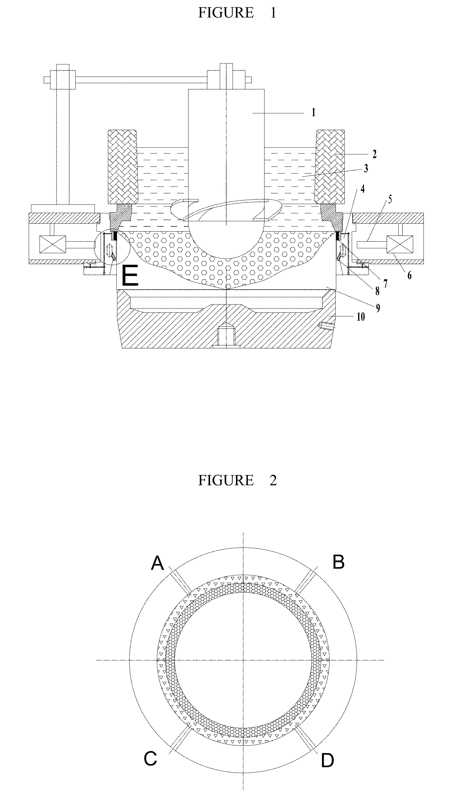
[0022] FIG. 1 is a schematic diagram illustrating the structure of a device of the present invention for preparing a high-quality large-sized aluminium alloy ingot.
[0023] FIG. 2 is a schematic diagram illustrating the partitioning of a graphite ring.
[0024] FIG. 3 is an enlarged diagram illustrating a partial area E of a mold of FIG. 1.
[0025] FIG. 4 is a schematic diagram illustrating a uniform cooler.
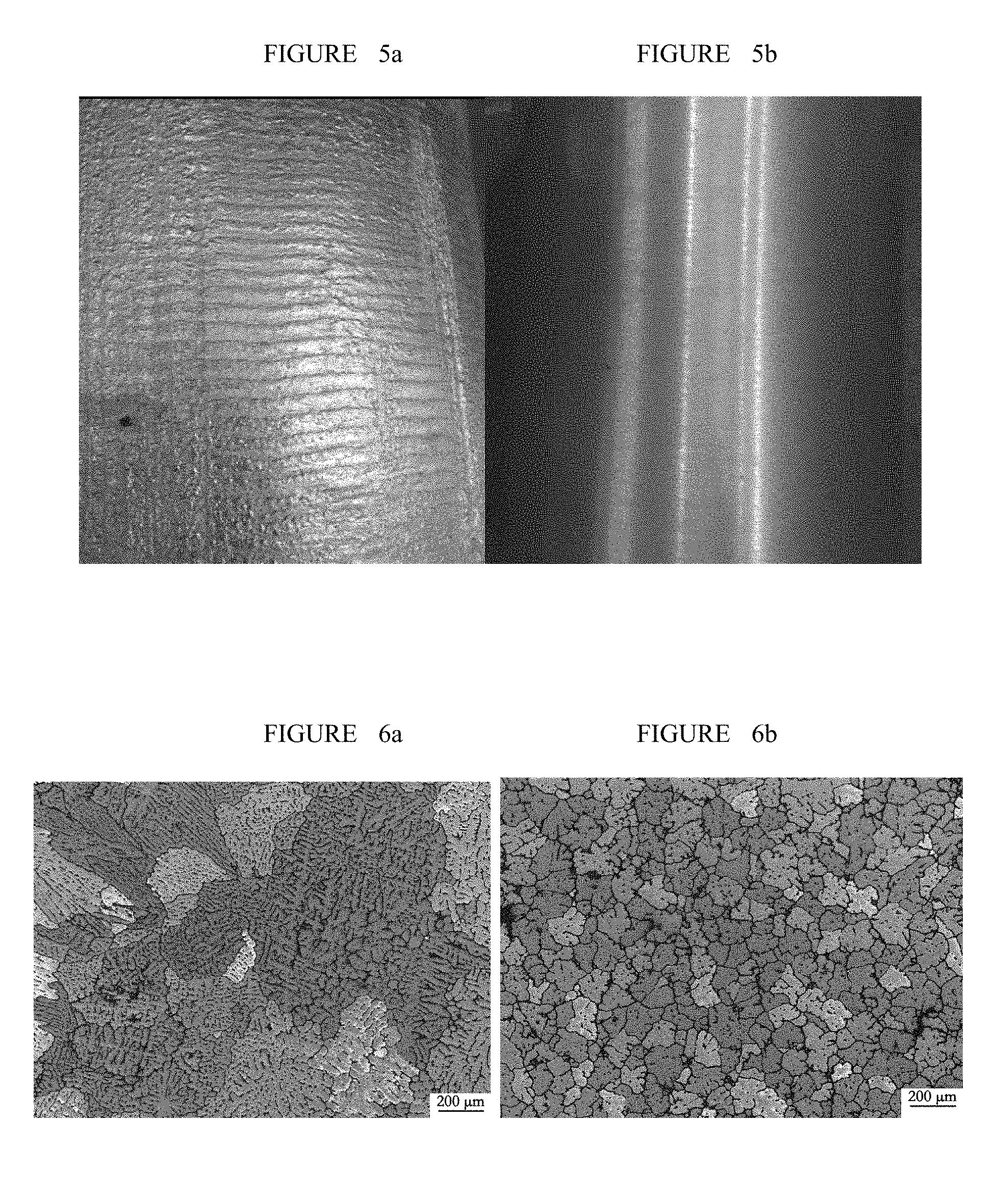
[0026] FIGS. 5a and 5b are pictures illustrating the surface appearances of 7075 aluminium alloy ingots (.PHI.=582 mm) prepared respectively by the common semi-continuous casting method and the present invention.
[0027] FIGS. 6a and 6b illustrate the microstructures of 7075 aluminium alloy ingots (.PHI.=582 mm) prepared respectively by the common semi-continuous casting method and the present invention.
[0028] Main reference numerals are illustrated as follows:
TABLE-US-00001 1 - uniform cooler; 2 - hot top; 3 - melt; 4 - oil-gas lubrication mold; 5 - magnet yoke; 6 - coil; 7 - graphite ring; 8 - water spraying holes; 9 - ingot; 10 - dummy ingot; 11 - oil groove; 12 - gas groove; 13 - upper row of water spraying 14 - lower row of water spraying holes; holes; 15 - heat insulation end; 16 - stirring blade; 17 - cooling end.
DETAILED DESCRIPTION OF THE PREFERRED EMBODIMENTS
[0029] The present invention may be implemented based on the following embodiments, but not limited thereto. These embodiments are merely for the purpose of illustrating the implementation process of the present invention, and not intended to limit the scope of the present invention in any way. In the following embodiments, various processes and methods that have not been described in detail are conventional methods known in the art.
[0030] As shown in FIG. 1, the device of the present invention comprises a uniform cooler 1, a hot top 2, a melt 3, an oil-gas lubrication mold 4, a magnet yoke 5, a coil 6, a graphite ring 7, water spraying holes 8, an ingot 9, a dummy ingot 10, etc. The hot top 2 is arranged above the oil-gas lubrication mold 4, the coil 6 and the magnet yoke 5 are arranged outside the oil-gas lubrication mold 4, the uniform cooler 1 is arranged inside the oil-gas lubrication mold 4, and the dummy ingot 10 is arranged below the oil-gas lubrication mold 4.
[0031] The oil-gas lubrication mold 4 comprises a mold body and a graphite ring 7 mounted above the mold body. The graphite ring 7 is provided with a gas groove 12 and an oil groove 11 on its outer wall, wherein the gas groove 12 is of a sectional design. As shown in FIG. 2, the gas groove 12 is divided into 3-20 sections, and each section of the gas groove 12 has a length of 100-500 mm, and is provided independently with an air intake passage for independent gas supply and control; the oil groove 11 is separated from the gas groove 12, and is arranged on an upper portion thereof. The graphite ring 7 is prepared by porous graphite, and gas and lubricating oil seep out of the mold through the graphite ring 7.
[0032] The oil-gas lubrication mold 4 is provided with two rows of water spraying holes, as shown in FIG. 3; water volumes of the two rows of water spraying holes are independently controlled; the upper row of water spraying holes 13 forms an angle of 15-30 degrees with respect to an inner wall of the oil-gas lubrication mold 4, and has a diameter of 1-5 mm; while the lower row of water spraying holes 14 forms an angle of 0-25 degrees (greater than 0 degree) with respect to a wall of the oil-gas lubrication mold 4, and has a diameter of 2-8 mm; the diameter of the upper row of water spraying holes needs to be smaller than or equal to that of the lower row of water spraying holes.
[0033] The magnet yoke 5 is of a telescopic design. The magnet yoke 5 is variable in length, and is retractable in a range of 0-100 mm. The electromagnetic induction coil 6 generates an electromagnetic field which is guided into a melt inside the mold via the magnet yoke 5. The electromagnetic coil 6 may generate a rotating electromagnetic field, a traveling wave electromagnetic field or a compound electromagnetic field.
[0034] During the semi-continuous casting operation, the uniform cooler 1 passes through the hot top 2 and stretches to a height where the oil-gas lubrication mold 4 is located. The uniform cooler 1 may be arranged to be one or more in number, and rotate at a rotational speed of 0-300 r/min. As shown in FIG. 4, the uniform cooler 1 is composed of an upper heat insulation end 15 and a lower cooling end 17, and the heat insulation end 15 is provided with a stirring blade 16; the upper heat insulation end 15 is of a cylindrical shape, which has an outer diameter of 100-800 mm, and is made of high temperature-resistant heat insulation material; the cooling end 17 is made of thermally conductive material, such as graphite, copper, molybdenum, titanium and composite materials thereof; the cooling end 17 of the uniform cooler 1 is of a spiral shape, and thus, the rotation of the uniform cooler 1 will force a melt to flow downward; the stirring blade is arranged to be 0-8 in number, and has a blade width of 10-100 mm and a thickness of 2-8 mm; the stirring blade 16 is made of high temperature-resistant material, such as copper, molybdenum, titanium, ceramic and composite materials thereof, and rotates along with the uniform cooler 1; during operation, it will drive the melt to converge towards the cooling end 17 of the uniform cooler 1; a circulating cooling medium is introduced into the uniform cooler 1, and reaches the cooling end 17 through which it exchanges heat with the melt, wherein the cooling medium may be air, nitrogen, water, oil and various other fluids, and has a flow of 0-2000 L/min. To achieve the continuous and dynamic uniform supercooling of a melt, the melt is made to pass through the bottom portion of the uniform cooler for cooling, and then continues to flow downward into the mushy zone of a liquid cave, thereby achieving the continuous and dynamic uniform cooling of the melt as well as forced feeding, and preparing a large-sized fine-grained homogeneous ingot.
[0035] The application method is as follows: during the semi-continuous casting operation, the overall device is preheated to 80-200 degrees Celsius, and a melt that has been refined and stabilized to be 80-100 degrees Celsius higher than the liquidus temperature is poured into this device. During the continuous casting operation: air and lubricating oil are introduced into the gas groove 12 and the oil groove 11 arranged on the outer wall of the graphite ring 7, wherein the flow of air is 500-5000 mL/min, while oil is supplied in a pulsed manner, with the oil supplying capacity being 60-100/s; the electromagnetic coil 6 is initiated, and the current is 10-200 A; the flow of the upper row of water spraying holes 13 is controlled to be 1-50 L/min, while that of the lower row of water spraying holes 14 is controlled to be 20-100 L/min; the speed of casting is 20-100 mm/min.
[0036] An alloy melt reaches the upper portion of the dummy ingot 10 through the hot top 2 and the mold 4, and the liquid surface of the melt is elevated to a desired height; after the continuous casting operation is initiated, the dummy ingot 10 descends slowly, and the flow of cooling water is increased slowly; after the casting process is stabilized, uniform cooling and electromagnetic stirring are applied until the casting process is completed, wherein the cooling intensity of the uniform cooling is 500-5000 W/(m.sup.2k), and the shearing rate of the electromagnetic stirring is 10-2000 s.sup.-1.
[0037] The 7075 aluminium alloy rounded ingot (.PHI.=582 mm) prepared by the present invention is required to have a smooth surface, and a fine and uniform internal structure. The specific implementation is as follows:
[0038] The structural schematic diagram of the device is as shown in FIG. 1. The oil-gas lubrication mold 4 employs a partitioned gas supply system, and the graphite ring 7 is provided externally with a gas groove 12 and an oil groove 11, wherein the gas groove 12 is divided into 4 sections, and each section of the gas groove 12 has a length of 456 mm, and is provided independently with an air intake passage for independent gas supply and control; the oil groove 11 is separated from the gas groove 12, and is arranged on an upper portion thereof, and the graphite ring 7 is prepared by porous graphite. The upper row of water spraying holes 13 forms an angle of 25 degrees with respect to a wall of the mold, and has a diameter of 2 mm; while the lower row of water spraying holes 14 forms an angle of 10 degrees with respect to the wall of the mold, and has a diameter of 5 mm. Water volumes of the two rows of water spraying holes may be independently controlled.
[0039] The uniform cooler 1 is arranged on a casting platform, and has a diameter of 300 mm. The cooler, the hot top and the mold are concentric, and the bottom end of the uniform cooler 1 is flush with that of the mold. The heat insulation end 15 of the uniform cooler 1 is made of high temperature-resistant heat insulation ceramic material, and has a diameter of 300 mm and a thickness of 10 mm; the lower cooling end 17 has a diameter of 350 mm, and is made of graphite; the blade is 3 in number, and has a width of 50 mm. The uniform cooler 1 has a rotational speed of 60 r/min.
[0040] The electromagnetic coil is arranged on the periphery of the oil-gas lubrication mold 4, which may generate a rotating electromagnetic field that applies shearing to an alloy melt, and the magnet yoke has a length of 50 mm.
[0041] During the semi-continuous casting operation, a melt that has been refined and stabilized to be 100 degrees Celsius higher than the liquidus temperature is poured into the hot top. Air and lubricating oil are introduced into the gas groove 12 and the oil groove 11 arranged on the outer wall of the graphite ring 7, wherein the flow of air is 1430 mL/min, while oil is supplied in a pulsed manner, with the oil supplying capacity being 80/s; the flow of the upper row of water spraying holes 13 is controlled to be 20 L/min, while that of the lower row of water spraying holes 14 is controlled to be 30 L/min; the speed of casting is 65 mm/min. The alloy melt reaches the mold through the hot top 2, and the liquid surface of the melt is elevated to a desired height; after the continuous casting operation is initiated, the dummy ingot 10 descends slowly, and the flow of cooling water is increased slowly; after the casting process is stabilized, uniform cooling and electromagnetic stirring are applied until the casting process is completed, wherein the cooling intensity of the uniform cooling is 1210 W/(m.sup.2k), and the shearing rate of the electromagnetic stirring is 110 s.sup.-1.
[0042] Through comparison of surface quality and internal structures between the 7075 aluminium alloy rounded ingot (.PHI.=582 mm) prepared by the common semi-continuous casting method and that prepared by the present invention, it is found that the ingot prepared by the common semi-continuous casting method is featured by poor surface quality and course internal structures, as shown in FIGS. 5a and 6a; however, the ingot prepared by the present invention has a smooth surface, a fine and uniform internal structure, and an average grain size of 154 .mu.m, as shown in FIGS. 5b and 6b.
* * * * *
D00000
D00001
D00002
D00003
XML
uspto.report is an independent third-party trademark research tool that is not affiliated, endorsed, or sponsored by the United States Patent and Trademark Office (USPTO) or any other governmental organization. The information provided by uspto.report is based on publicly available data at the time of writing and is intended for informational purposes only.
While we strive to provide accurate and up-to-date information, we do not guarantee the accuracy, completeness, reliability, or suitability of the information displayed on this site. The use of this site is at your own risk. Any reliance you place on such information is therefore strictly at your own risk.
All official trademark data, including owner information, should be verified by visiting the official USPTO website at www.uspto.gov. This site is not intended to replace professional legal advice and should not be used as a substitute for consulting with a legal professional who is knowledgeable about trademark law.