Anti-fatique Comfort Mat
Publicover; Mark W.
U.S. patent application number 16/000817 was filed with the patent office on 2019-01-10 for anti-fatique comfort mat. The applicant listed for this patent is Mark W. Publicover. Invention is credited to Mark W. Publicover.
| Application Number | 20190008302 16/000817 |
| Document ID | / |
| Family ID | 64903698 |
| Filed Date | 2019-01-10 |


View All Diagrams
| United States Patent Application | 20190008302 |
| Kind Code | A1 |
| Publicover; Mark W. | January 10, 2019 |
ANTI-FATIQUE COMFORT MAT
Abstract
Disclosed is a standing platform having granular material, such as sand, with the granular material positioned to support a user standing on an upper surface of the platform when the platform rests on a floor surface.
| Inventors: | Publicover; Mark W.; (Saratoga, CA) | ||||||||||
| Applicant: |
|
||||||||||
|---|---|---|---|---|---|---|---|---|---|---|---|
| Family ID: | 64903698 | ||||||||||
| Appl. No.: | 16/000817 | ||||||||||
| Filed: | June 5, 2018 |
Related U.S. Patent Documents
| Application Number | Filing Date | Patent Number | ||
|---|---|---|---|---|
| 15437349 | Feb 20, 2017 | 10045647 | ||
| 16000817 | ||||
| PCT/US2016/029618 | Apr 27, 2016 | |||
| 15437349 | ||||
| 62515483 | Jun 5, 2017 | |||
| 62565060 | Sep 28, 2017 | |||
| 62245268 | Oct 22, 2015 | |||
| 62211856 | Aug 30, 2015 | |||
| 62182429 | Jun 19, 2015 | |||
| 62153505 | Apr 27, 2015 | |||
| Current U.S. Class: | 1/1 |
| Current CPC Class: | A47G 27/0231 20130101 |
| International Class: | A47G 27/02 20060101 A47G027/02 |
Claims
1. A standing platform, comprising: a container having an inner surface that defines a receptacle; and a volume of a granular material contained within the receptacle, wherein the location and amount of the granular material are sufficient for the granular material to support a user standing on the platform when the platform rests on a floor surface.
2. The standing platform of claim 1 wherein: the container comprises an envelope having an inner surface that defines a chamber; and the volume of a granular material contained within the chamber, an upper portion of the envelope is an upper membrane that is flexible, the envelope has an envelope upper surface that is a portion of the upper membrane, at least a portion of the envelope upper surface is located over the volume of granular material when the platform rests on a floor surface, and the location and amount of the granular material are sufficient for the granular material to support a user standing on the upper surface when the platform rests on a floor surface.
3. The standing platform of claim 2 wherein the envelope is sufficiently nonporous to prevent the escape of granular material from the chamber.
4. The standing platform of claim 2 wherein the envelope further comprises a lower membrane, the upper membrane and lower membranes being secured together at a perimeter seam to define the cavity.
5. The standing platform of claim 2 wherein the granular material is distributed in a layer of substantially uniform thickness throughout the envelope.
6. The standing platform of claim 2 having: a length, measured across a greatest span of the upper surface, that is perpendicular to a greatest width measured across the upper surface, the length being no longer than 39 inches and no shorter than 16 inches; and the greatest width being no longer than 25 inches.
7. The standing platform of claim 2 further comprising a base and wherein: the base has a base upper surface that faces upwardly when the base rests on a floor surface and a base lower surface that faces substantially opposite to the base upper surface, the base lower surface contacting the floor surface when the base rests on the floor surface; and the envelope has an envelope lower surface that rests on the base.
8. The standing platform of claim 7 wherein the envelope lower surface is secured to the base upper surface.
9. The standing platform of claim 2 further comprising: a base having a base upper surface that faces upwardly when the base rests on a floor surface and a base lower surface that faces substantially opposite to the base upper surface, the base lower surface contacting the floor surface when the base rests on the floor surface; and a pad that rests on the base upper surface, and wherein the envelope has an envelope lower surface that rests on the pad.
10. The standing platform of claim 9 wherein the pad is a foam pad or a gel pad.
11. The standing platform of claim 9 wherein the pad is secured to both the envelope lower surface and the base upper surface.
12. The standing platform of claim 9 wherein the base is an inflatable bladder.
13. The standing platform of claim 9 wherein the base lower surface is convex so that when the platform rests on a floor surface with a user standing on the upper surface, the user can cause the standing platform to rock by shifting weight.
14. The standing platform of claim 9 wherein the base upper surface defines a seat that is configured to receive the envelope.
15. The standing platform of claim 14 wherein: the standing platform comprises plural of the envelopes; and the base upper surface defines plural seats, each of which seats is configured to receive one of the envelopes.
16. The standing platform of any of claim 7 wherein the base further comprises at least two terrain bodies that extend upwardly from the base upper surface at locations below the envelope.
17. The standing platform of claim 1 further comprising at least one inclusion body contained within the chamber.
18. The standing platform of claim 17 wherein the at least one inclusion body is secured to the inner surface of the envelope.
19. The standing platform of claim 17 wherein the at least one inclusion body is not secured to the inner surface of the envelope.
20. The standing platform of claim 17 wherein: the at least one inclusion body is a pouch; and the pouch contains a granular material that differs from other granular material in the chamber.
21. (canceled)
22. (canceled)
23. (canceled)
24. (canceled)
Description
CROSS REFERENCE TO RELATED APPLICATIONS
[0001] This claims the benefit of U.S. Provisional Application No. 62/515,483, filed Jun. 5, 2017, and U.S. Provisional Application No. 62/565,060, filed Sep. 28, 2017.
[0002] This is a continuation-in-part of application Ser. No. 15/437,349, filed Feb. 20, 2017, which is a continuation of International Application No. PCT/US2016/029618, filed Apr. 27, 2016, which claims the benefit of U.S. Provisional Application No. 62/245,268, filed Oct. 22, 2015, U.S. Provisional Application No. 62/211,856, filed Aug. 30, 2015, U.S. Provisional Application No. 62/182,429, filed Jun. 19, 2015, and U.S. Provisional Application No. 62/153,505, filed Apr. 27, 2015.
[0003] All of the above-named applications are incorporated herein by reference in their entireties.
SUMMARY
[0004] Disclosed is a standing platform containing sand or sand like material. Said mat may be of any polygon or shape and any perimeter shape, coupled to the top, bottom or base side of any standing platform of any polygon or three dimensional shape and any perimeter shape or outline. The sand material mat may be sized and shaped to follow the contours of any device to which it is attached. Said standing platform containing a sand mat will generally contact the ground surface which in turn permits predetermined movement profiles. Also disclosed is a platform FIGS. 1A-7D disclose multiple versions of this concept. With the disclosed engineered and tested sand levels, a standing user is able to control the quantity and comfort beneath their feet while standing on the top surface of the sand mat, whether coupled to another standing platform, or alone, without being coupled to another platform. Various materials may be used in concert with the sand layer in the types and versions discussed in this disclosure to improve or alter the feeling under foot.
[0005] Disclosed is a device that provides increased safety for a standing user. First, standing on a sand based layer helps secure and stabilize the foot from slipping easily on or off of a standing platform or surface. This is especially true if that standing surface is unstable, either by design or inadvertence. Secondly, a sand based surface slows the reactivity of a standing platform that moves, such as a rocking board or other type of instability board or platform. This quality is especially beneficial to users who lack balance, either by age or physical condition. A sand based surface helps stabilize the feet and slows the speed at which a user's foot movement energy is transferred to a standing platform, thus dampening excessive speed of movement. The movement on such a board is slower and more muted because a user's foot pressure and movement energy is dampened as that energy is transferred through the sand layer to a standing platform to which the sand surface layer is attached. The sand containing layer may be placed directly underfoot, which is the most desirable because of the feel underfoot, but may also be coupled to a board in concert with other layers, such as foam or other resilient material. If the sand layer is placed in direct contact with the ground, then movement of the board is diminished due to the stabilizing influence of a sand base. Multiple layers of sand containing sheets (sand filled containers that are generally horizontal and flat of various depths or thicknesses) could be used together on a single standing platform. For example, a sheet of sand could be placed on the surface where a user's feet are in direct contact, but a second sand sheet could be placed closer to the ground surface between other layers of foam or other material. Although not in direct contact with a user's feet, the other sand sheet will help soften the overall feel of the board to the user, and help modulate and delay reactivity of an unstable platform such as a rocker or instability board.
[0006] Being barefoot on sand has its appeal, but it also has many possible health benefits. There are several reasons why standing on sand is beneficial: First, one experiences improved Proprioception. Proprioception--a favorite term among barefoot runners and fans of minimal shoes--is defined as the ability to sense stimuli arising within the body regarding position, motion, and equilibrium. Basically, good proprioception means your mind is in touch with the stimuli coming from your feet, which helps you connect with the world around you. While thickly-padded conventional mats can numb this ability, standing on a sand-based surface separately, or in concert with a standing platform while barefoot or in stocking feet is an extremely beneficial way to tap into this effect. A person has between 3,000-7,000 nerve endings in each foot. Feeling the sand grains under the sensitive part of your arch or between your toes is comfortable and stimulating. Also, sand acts as a natural cushion for feet, and one that people immediately recognize and associate with being at the beach. This in turn can increase a sense of well-being because of the positive association.
[0007] The sand may be secured, housed or otherwise contained in materials of varying thickness. For example, to increase the likelihood of feeling improved Proprioception, a very thin top layer over the sand may be employed; so that the user's feet maximize the beneficial feeling of sand underfoot without allowing the sand to escape. The foot contact material separating the sand from the user's foot may be made of a stretchier or more elastic material, to more closely achieve a feeling of direct contact with sand underfoot. In areas where foot contact is not anticipated, the material can be thicker and made more durable to increase the overall strength of the sand containing envelope.
[0008] The sand containing envelope may be removable from a standing platform to which it is compatible or attachable. For example, the design shown in FIG. 4 is one way to express this concept. 401 may be nested into a standing platform designed to receive and secure (either by simple tension, or attachment or coupling), a sand containing envelope. A user may remove or otherwise detach the sand layer from the rest of the standing platform in order to be used separately. Some users may suffer from balance issues due to medical conditions such as diabetes or age, or other conditions that results in inhibited balance while standing. They may utilize the sand mat without it being attached to an elevated board or instability board. The result is a weighted, steady and more secure platform on which they may stand, that still provides safer method to provide positive stimulation underfoot.
[0009] The sand containing layer may be of varying thicknesses ranging from a very thin 1 millimeter to a relatively thick 77 millimeters. Thicknesses greater than 51 millimeters result in a heavier surface that becomes more difficult to move for some due to the additional weight. In such cases, portability of the surface can suffer. Any thicker and the weight and height of the sand can become counterproductive to balance and safety for some users. Optimally, the range will likely vary somewhere between 2 millimeters and 51 millimeters. The sand contained within the layer may possess various properties and types to improve or alter the feeling underfoot; or to change its properties, and dynamics. For example, the sand may be composed of a portion of coarse sand and fine sand in varied combinations. The sand may contain non-sand bodies such as beads or balls of plastic, wood, metal or other materials that vary in firmness so that they may range from soft to hard, and may vary in any three-dimensional shape to stimulate the feeling and comfort underfoot and to alter and fine tune desired characteristics. The non-sand materials contained within the sand layer may comprise any percentage of the material in the layer so that sand is the majority component or the minority component in any combination or percentage. The size of both the sand granules and other non-sand materials may vary as well.
[0010] If one's feet are confined in tight or constricting shoes all day, then removing them from constricting shoes during standing, and letting toes move and stretch out, naturally provides relief to one's feet. Sand conforms to feet without restricting them, so it's almost like a standing foot massage, meaning one gets the added benefit of the sand pressing, rubbing and otherwise stimulating (through the containing layer) the soles of their feet, which in turn activates venous and lymphatic circulation. To adjust the feel of sand underfoot, one naturally "works" or presses their foot deeper into the sand based surface, which in turn stimulates muscle action, tendon extension and overall foot exercise and manipulation. This natural activity stimulates muscles, and improves blood flow in the feet and adjacent appendages, contributing to improved overall feeling and alertness.
[0011] A study from the University of Exeter suggested that people who spent more time on beaches had less stress and better overall health. Another, more esoteric benefit is called grounding or "Earthing". The theory behind grounding, also known as earthing, is that electrical energy from the earth can be absorbed through your feet when you walk or stand barefoot on sand and lead to a multitude of health benefits. Even if one takes such a theory as dubious, there is no denying that feeling sand mold underfoot is a pleasurable and stimulating activity that would be desirable during a long day at the office. According to a study from the University of Gothenburg in Sweden, staying constantly plugged into electrical devices has been associated with stress, loss of sleep and depression. The disclosed device and its variants help achieve these benefits for a standing worker in the office environment where a standing desk is employed, or in any other environment where a person is required to stand for periods of time.
DRAWING DESCRIPTIONS
[0012] FIG. 1A is a front view of an air platform with a sand mat attached on top.
[0013] FIG. 1B is a side cross section view of an air platform with a sand mat attached on top.
[0014] FIG. 1C is a detailed side cross section view of an air platform with a sand mat attached on top.
[0015] FIG. 1D is an upper angled view of an air platform with a sand mat attached on top.
[0016] FIG. 1E is an exploded upper angle view of an air platform with a sand mat attached on top.
[0017] FIG. 2A is a front view of a rocking platform with a sand mat on top.
[0018] FIG. 2B is a side cross section view of a rocking platform with a sand mat on top.
[0019] FIG. 2C is a detailed side cross section view of a rocking platform with a sand mat on top.
[0020] FIG. 2D is an upper angled view of a rocking platform with a sand mat on top.
[0021] FIG. 2E is an exploded upper angled view of a rocking platform with a sand mat on top.
[0022] FIG. 2F is a side cross section view of a rocking platform with a thin sand mat on top.
[0023] FIG. 2G is a side cross section view of a rocking platform with a thicker sand mat on top.
[0024] FIG. 2H is a side cross section view of a rocking platform with a medium thickness sand mat on top with a foam mat in between it and the rockable platform.
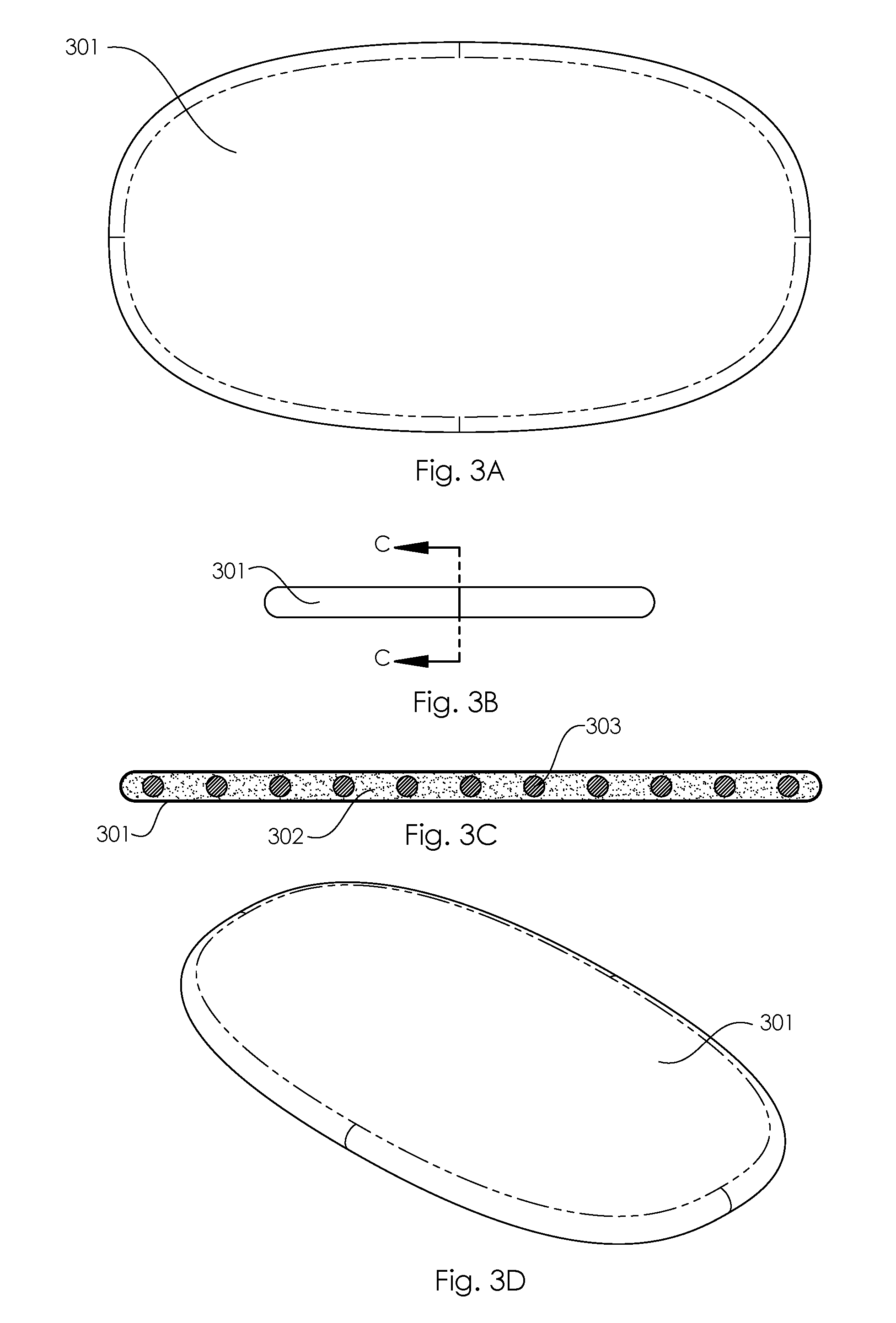
[0025] FIG. 3A is a top view of a sand filled mat that has solid features inside of it.
[0026] FIG. 3B is a side view of a sand filled mat that has solid features inside of it.
[0027] FIG. 3C is a front cross section view of a sand filled mat that has solid features inside of it.
[0028] FIG. 3D is an isometric view of a sand filled mat that has solid features inside of it.
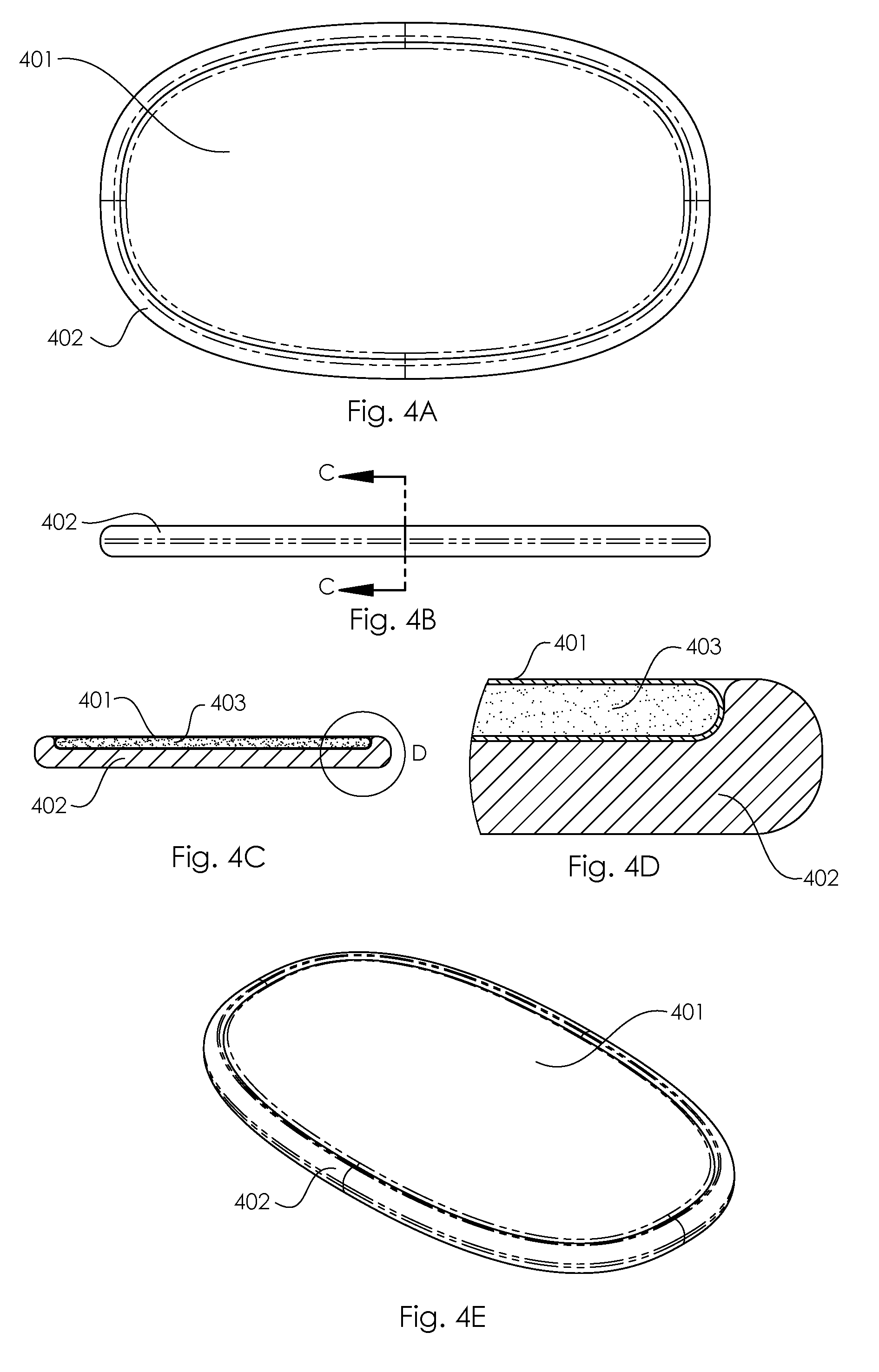
[0029] FIG. 4A is a top view of a foam mat with a recessed sand mat.
[0030] FIG. 4B is a front view of a foam mat with a recessed sand mat.
[0031] FIG. 4C is a side cross section view of a foam mat with a recessed sand mat.
[0032] FIG. 4D is a detailed side cross section view of a foam mat with a recessed sand mat.
[0033] FIG. 4E is an isometric view of a foam mat with a recessed sand mat.
[0034] FIG. 5A is an exploded upper angled view of a mat with a textured surface sand mat.
[0035] FIG. 5B is an upper angled view of a mat with a textured surface with a sand mat nested on it.
[0036] FIG. 5C is a front view of a mat with a textured surface with a sand mat nested on it.
[0037] FIG. 5D is a side cross section view of a mat with a textured surface with a sand mat nested on it.
[0038] FIG. 5A is an angled upper view of a base mat and a sand mat next to it
[0039] FIG. 5B is an angled upper view of a sand mat placed inside of a base mat.
[0040] FIG. 5C is a front view of the sand mat nested inside a base mat.
[0041] FIG. 5D is a side cross section view of the sand mat nested inside a base mat pressed or coupled to raised bump features at or near the bottom of the sand mat.
[0042] FIG. 6A is a top view of a multi-layer sand board.
[0043] FIG. 6B is a front view of a multi-layer sand board.
[0044] FIG. 6C is a side cross section view of a multi-layer sand board.
[0045] FIG. 6D is a side detailed cross section view of a multi-layer sand board.
[0046] FIG. 6E is an isometric view of a multi-layer sand board.
[0047] FIG. 7A is a top view of a partitioned sand platform with vertical baffles.
[0048] FIG. 7B is a front cross section view of a partitioned sand platform with vertical baffles.
[0049] FIG. 7C is a top view of a partitioned sand platform with vertical wave baffles.
[0050] FIG. 7D is a front cross section view of a partitioned sand platform with vertical wave baffles.
[0051] FIG. 7E is a top view of a partitioned sand platform with vertical hourglass baffles.
[0052] FIG. 7F is a front cross section view of a partitioned sand platform with vertical hourglass baffles.
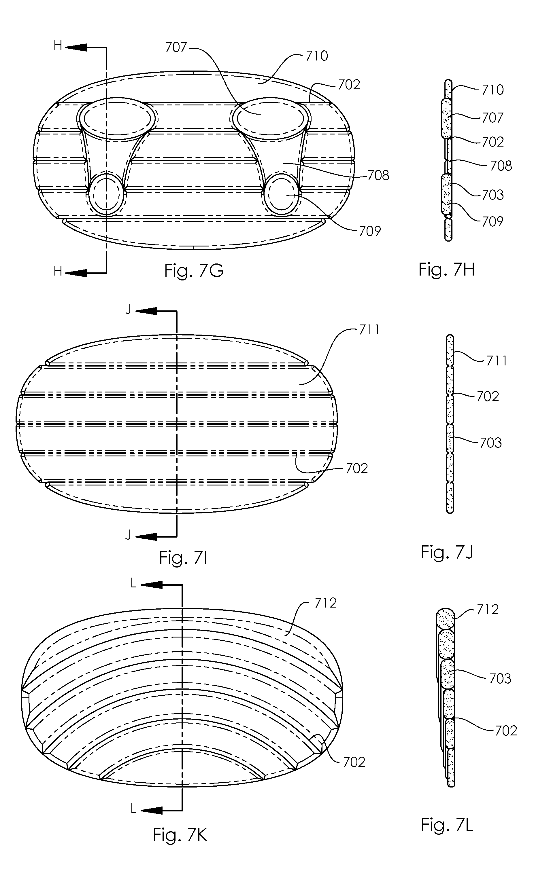
[0053] FIG. 7G is a top view of a partitioned sand platform with foot conforming baffles.
[0054] FIG. 7H is a side cross section view of a partitioned sand platform with foot conforming baffles.
[0055] FIG. 7I is a top view of a partitioned sand platform with horizontal baffles.
[0056] FIG. 7J is a side cross section view of a partitioned sand platform with horizontal baffles.
[0057] FIG. 7K is a top view of a partitioned sand platform with concentric baffles.
[0058] FIG. 7L is a side cross section view of a partitioned sand platform with concentric baffles.
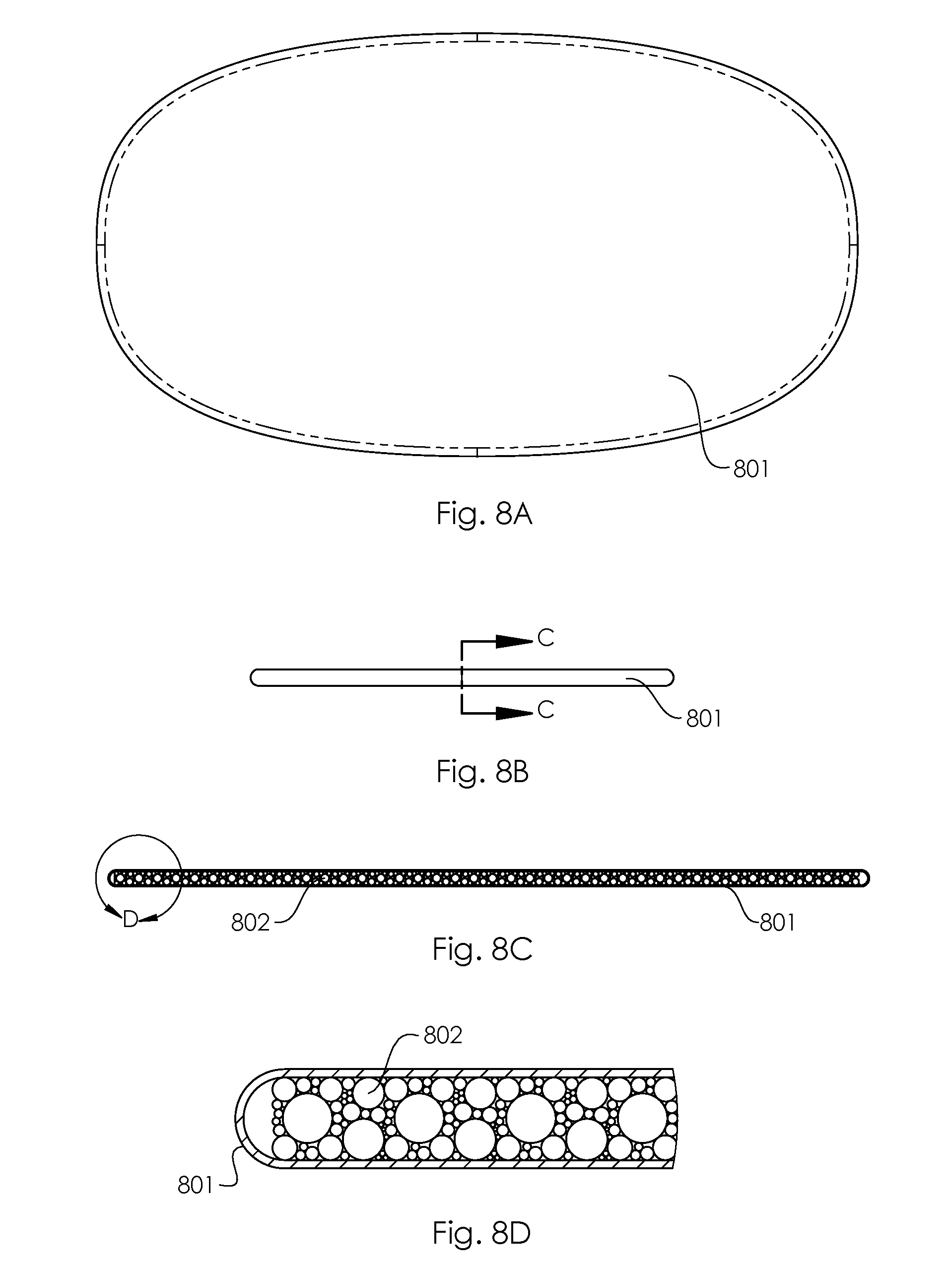
[0059] FIG. 8A is a top view of a platform filled with a granular material of different particle size.
[0060] FIG. 8B is a side view of a platform filled with a granular material of different particle size.
[0061] FIG. 8C is a front cross section view of a platform filled with a granular material of different particle size.
[0062] FIG. 8D is a detailed front cross section view of a platform filled with a granular material of different particle size.
[0063] FIG. 9A is a top view of a connected dual pad platform filled with a granular material.
[0064] FIG. 9B is a front view of a connected dual pad platform filled with a granular material.
[0065] FIG. 9C is an isometric view of a connected dual pad platform filled with a granular material.
[0066] FIG. 9D is a top view of a connected dual oval pad platform filled with a granular material.
[0067] FIG. 9E is a front view of a connected dual oval pad platform filled with a granular material.
[0068] FIG. 9F is an isometric view of a connected dual oval pad platform filled with a granular material.
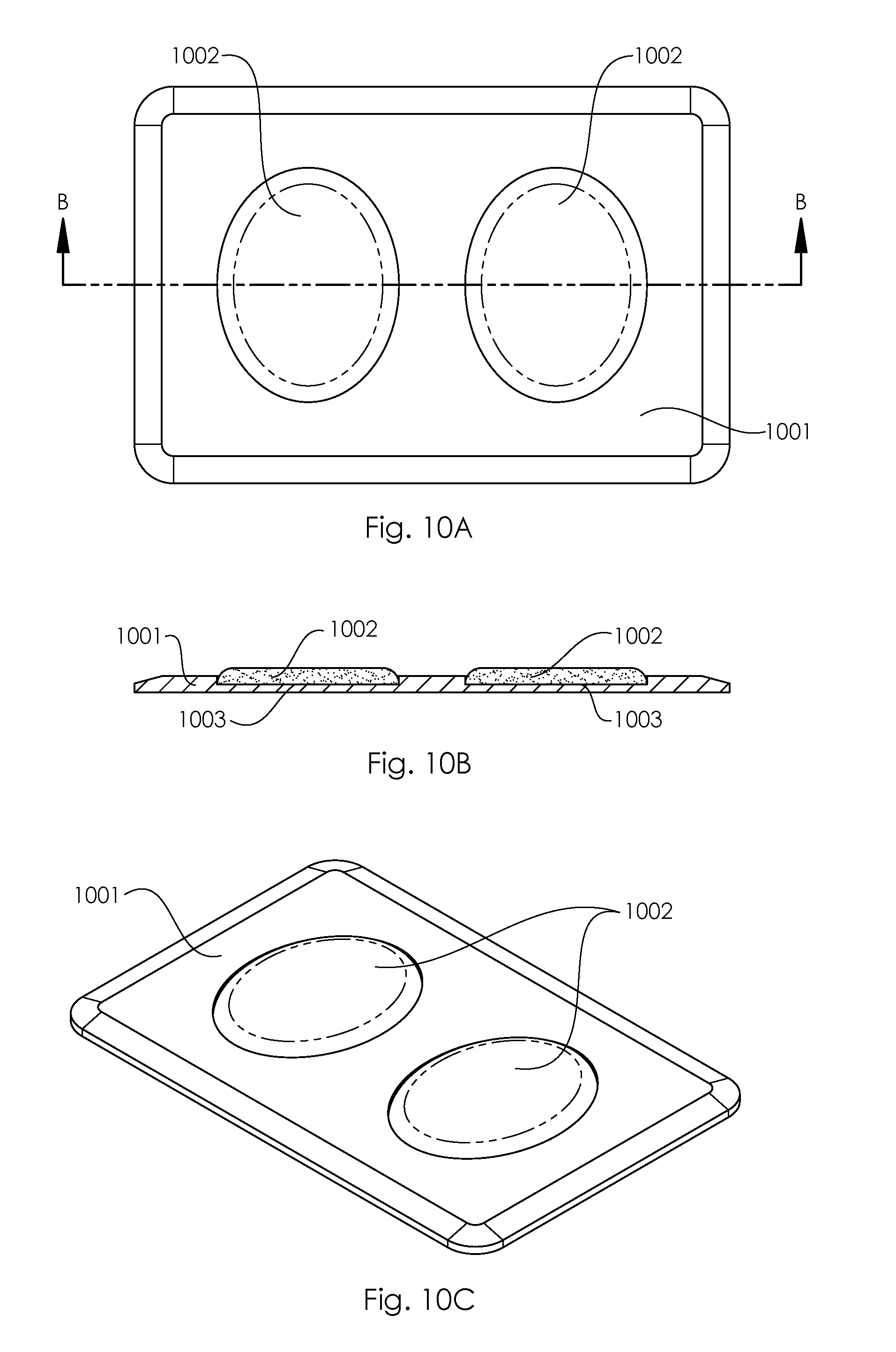
[0069] FIG. 10A is a top view of a foam standing pad with integrated granular filled inserts.
[0070] FIG. 10B is a front cross section view of a foam standing pad with integrated granular filled inserts.
[0071] FIG. 10C is an isometric view of a foam standing pad with integrated granular filled inserts.
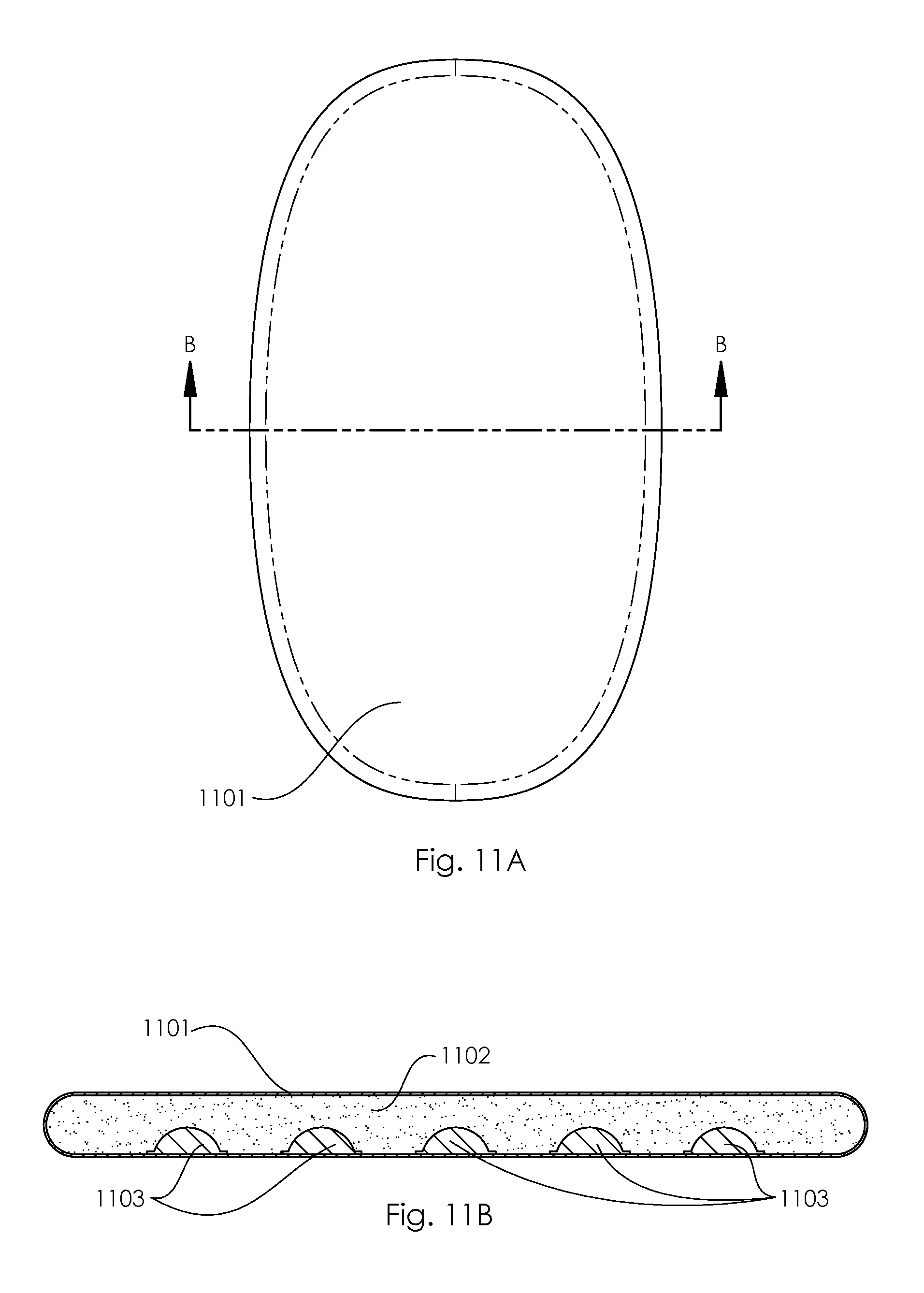
[0072] FIG. 11A is a top view of a granular filled standing pad with fixed internal bumps.
[0073] FIG. 11B is a side cross section view of a granular filled standing pad with fixed internal bumps.
[0074] FIG. 12A is a top view of a granular filled standing pad with internal pouches.
[0075] FIG. 12B is a side cross section view of a granular filled standing pad with internal pouches.
DETAILED DESCRIPTION
[0076] FIG. 1A is a front view of an inflatable standing platform 103 with a sand mat 101 on it. The sand mat 101 has a perimeter rim 102 that helps hold the mat 101 in place on the standing platform 103. FIG. 1B is a side cross section view showing the sand mat 101, the perimeter rim 102, the inflatable platform 103, the sand inside the mat 104, and the drop stitch fibers inside of the inflatable 105. FIG. 1C is a detailed side cross section view. This shows how the perimeter rim 102 extends over the side of the inflatable platform 103 to help center the sand mat 101. The sand mat 101 is shown to curve over the edge of the inflatable platform 103 slightly. This extends the sand feel further to encompass the edges. The sand mat 101 could also be flat or generally horizontally disposed. FIG. 1D is an angled view showing the sand mat 101 on top, the inflatable platform 103 as a base, and the perimeter rim 102 extending over the top edge of the inflatable platform 103. FIG. 1E is an exploded view showing the sand mat 101 with perimeter rim 102 lifted off exposing the inflatable platform 103. This allows the sand mat to be added as an accessory and installed on an existing inflatable platform. The installation may be achieved by tension, hook and loop closures, or other coupling methods such as snaps, etc. to ensure the sand envelope stays in the desired position while a standing user is engaging it.
[0077] FIG. 2 shows a sand containing envelope coupled to a rockable platform. FIG. 2A is a front view of a rocking platform comprised of a curved base 203, a flat top 202, with a sand mat 201 coupled to the top or upper surface. FIG. 2B is a side cross section view of the rocking platform with sand mat 201 attached. FIG. 2C is a more detailed close up of the side cross section view showing the sand mat 201 filled with sand 204, on top of the rocking platform flat top 202 which caps onto the rocking base 203. Generally, the rocking base 203 will be comprised of a rigid material to give a consistent rocking action, and the sand 204 will act as the compliant material to provide a pleasant surface feel as previously discussed. FIG. 2D is an angled view showing the sand mat 201 on the rocking platform top 202 and base 203. FIG. 2E is an angled exploded view showing the sand mat 201 removed from the rocking platform top 202 and base 203. FIG. 2F is a side cross section view showing a thin sand mat 201 on a rocking platform. The thin mat will minimize weight or minimize any height increase, and will provide a feel that is pleasant without letting the user sink down excessively. FIG. 2G is a side cross section view showing a thicker sand mat 205 on a rocking platform. This mat will provide the user with a deeper and realistic feel and it will allow the user's feet to travel into the sand more for more stability and different feel underfoot. However, it will be of a greater weight. The thicker sand surface may be decoupled and used as a separate standing surface, in this case, one that no is no longer rockable, and is lower in overall height. The sand containing layer may be detached in this manner regardless of thickness. Or, the sand containing layer may include non-sand portions that are used in concert with the sand for varied feel and weight underfoot.
[0078] FIG. 2H is a side cross section view showing a medium thickness sand mat 206 on a foam pad 207 which is on a rocking platform. The sand helps suppress excessive movement and help reduce the reactiveness of the rocking action. Slowing the overall reaction time provides additional safety for those users that have difficulty maintaining their balance for physical or mental reasons. It should be apparent that the thickness of the sand mat may be of any thickness from thin up to multiple inches thick. This sandwich of layers provides a unique feel under foot. By adjusting the density of the foam and the thickness of the sand, either more stable or more compliant properties can result. The layers can also be rearranged so that the foam is on top, and the sand is sandwiched between the foam and rigid base. There can also be multiple layers such as a foam, sand, foam, base arrangement, etc. Many different materials and combinations can be conceived to create the optimal surface feeling.
[0079] FIG. 3A is a top view of a sand mat or envelope 301 with internal solid features. FIG. 3B is a side view of a sand mat 301 with internal solid features. FIG. 3C is a front cross section view of a sand mat 301 filled with sand 302 with internal solid features 303. The solid features 303 are evenly distributed in the sand medium 302. The solid features 303 can be rigid or semi rigid, but they do not flow freely like the grains of sand 302, so they will provide firmer feeling bumps to the user's feet. This has massage and therapeutic benefits. The size of solid features 303, number of solid features 303, and solid feature materials can all be adjusted to change the feel. The solid features 303 are shown as round objects, but they can be of any 3-dimensional shape and size such as pyramids or asymmetrical polygons or any other three dimensional shape of varying curves and not flat sides. The solid features 303 can be independent bodies and are free to move relative to each other, or they can be connected to keep the pattern evenly distributed. FIG. 3D is an angled view of the sand mat 301 with internal solid features. Although, not shown, it should be noted that the solid features may vary in length, such as rods disposed in varying patterns or free-floating, or the like, to vary the feel underfoot within the sand medium. Also, the solid features can be resting at the bottom of the mat because they can shift to the bottom. Or the solid features could be put in, and then the sand material may be filled in on top of them.
[0080] FIG. 4A is a top view of a foam platform 402 with a recessed edge containing a sand mat 401. FIG. 4B is a front view of a foam platform 402 containing a sand mat 401. FIG. 4C is a front cross section view of a foam platform 402 containing a sand filled mat 401, and 403. FIG. 4D is a detailed cross section view showing how the foam platform 402 has a recessed surface that the sand mat 401 sits within. Allows the sand mat 401 surface to be flush with the top edge of the foam mat 402; which in turn keeps the sand mat 402 in place and creates a smooth top surface. FIG. 4E is an isometric view showing the sand mat 401 nested inside the foam mat 402.
[0081] FIG. 5A is an angled upper view of a base mat 501 and a sand mat 503 next to it. The base mat 501 has a textured surface comprised of a pattern of raised bump features 502. The base mat 501 is also shown to have two raised terrain features 504 that the user can stand on with their foot arches and in a variety of other positions. The terrain features 504 can be fixed in position, or they can be removable so the user may reposition them where desired. The terrain features 504 are shown as smooth domes, but they could be any number of different shapes that provide pleasing standing positions including log shapes, sharper domes, or insole (foot or shoe) shaped. The base mat 501 can be made of a variety of materials including foam that is soft, along an increasingly firmer material such as a hard plastic. This shows that the sand mat 503 and the base mat 501 may both be used as stand-alone mats. FIG. 5B is an angled upper view of a sand mat 503 placed inside of the base mat 501. This shows that the sand mat 503 fits inside of the recessed area of the base mat 501. By putting the two mats together it provides a composite feel of the two mats so that the surface has a nice sand feel while also having harder massage points. FIG. 5C is a front view of the sand mat 503 nested inside the base mat 501, having a surface containing raised bumps.
[0082] It should be apparent that the bumps may be of any polygonal shape or three dimensional solid or amorphous shape, and in any pattern in relations to other solid parts. Shown is an even distribution of bumps or three dimensional extensions, being equidistant from each other. But, these extensions or bumps may follow a pattern of greater spaces between each bump or greater spaces between groups of bumps that are sorted or combined together in various patterns. Thus, some portions of said surface may be completely devoid of bumps or extensions, while other portions contain them. FIG. 5D is a side cross section view of the sand mat nested inside a base mat pressed or coupled to raised bump features at or near the bottom of the sand mat.
[0083] FIG. 5D is a side cross section view of the sand mat 503 nested inside the base mat 501. This view shows how the raised bump features 502 press into the bottom of the sand mat 503. This compresses the sand 505 in these areas which creates a non-uniform feel across the mat surface. This provides massage benefits by having firmer and softer area press against the user's feet.
[0084] FIGS. 6A-6E describes a version of the disclosed device that incorporates an adjacent layer of gel-like material, or memory foam type material commonly made of a viscoelastic material. Such material takes time to return to its original shape in a manner known as hysteresis, absorbing energy before slowly returning to shape. By utilizing such materials in tandem, less sand may be used in the sand layer to reduce overall weight, or to produce a more equivalent or a more preferred feel underfoot without the need for additional sand. Sand is generally not viscoelastic, but the combination of sand with this material can be of great benefit to a standing user. This can be achieved in several versions, but usually, the gel or memory foam type layer will be generally adjacent in whole or in part with the sand containing layer. The foam layer may be hybridized or combined in multiple layers, such as gel foam, cooling vented type foam and memory foam in various combinations; in addition to a sand layer disposed above or below the hybridized or combined foam type layer. Other combinations may be considered to work in concert with the sand layer, such as water, air as previously discussed, beads of plastic or other materials, shavings, beads or other small shapes of various materials like wood or wood pulp, grains, buckwheat, or bamboo, etc. that behave similarly. The material used is less important so long as the result is a feeling similar to sand underfoot that is lighter or more comfortable, while maintain a more sand-like the feeling underfoot.
[0085] FIG. 6A is a top view that shows a thin sand layer 601 sitting inside a base platform 602. FIG. 6B is a side view showing the base platform 602. FIGS. 6C and D are cross section views that show the base platform 602 has a recessed cutout and that there is an extra layer of material 604 between the thin sand pad 601 and the base platform 602. The extra layer 604 can be a gel or foam type of material discussed that provides similar benefits as standing on sand, such that a thinner sand mat or layer 601 may be used. FIG. 6E is an isometric view showing the sand mat 601 sitting in the base platform 602. The composition may be altered so that the base, 602, is made of granular material or sand, and the other layers, either 603 and/or 604 may contain non-sand materials previously described in any combination. This allows for altering the feel and support to optimize performance and comfort for any number of users.
[0086] FIG. 7A-L shoes how segmenting the sand portions in various patterns by stitching or sealing isolated pockets of sand. This pockets can resemble pillow shapes along a horizontal plane or in three dimensions with additional depth. FIG. 7A shows a partitioned sand mat that has seams 702 to create vertical baffles 704. FIG. 7B is a front cross section view showing the vertical baffles 701 are filled with sand 703. The seams 702 are areas where the sand containing material of the mat pinches down and is connected. FIG. 7C shows a partitioned mat with wave shaped vertical baffles 704. The curved seams 702 provide comfortable places for the user to put their feet. FIG. 7E shows a partitioned mat with hour glass shaped vertical baffles. The baffles alternate between shapes the cut in 706 and bulge out 705. This creates a symmetrical baffling across the center plane of the board which is well suited for interacting with the user's feet. The placement of the sand containing baffles may vary to resemble beneficial shapes. For example, some baffles may be foot shaped serving to reduce overall weight while still providing the desired benefits directly underfoot, FIG. 7G. Other shapes and patterns not shown may be conceived that maximize any intended benefits.
[0087] FIG. 7G shows a partitioned mat with baffling specifically designed to accommodate a user's feet. It is comprised of forefoot pads 707, arch pads 708, heel pads 709, and horizontal baffles 710 complete the rest of the board. FIG. 7H is a side cross section view which shows that the different baffles have varying thicknesses. This shows that the forefoot pad 707 and heel pad 709 are extra thick to provide additional cushioning in those specific areas, and the arch pad 708 is thinner. These formations could be different such that the arch pad 708 could be thicker to provide additional arch support. The optimal shape may vary depending on the user's feet. Such structures may therefore be customizable for such adaptation.
[0088] FIG. 7I shows a partitioned sand pad with horizontal baffles 711. FIG. 7K shows a partitioned sand pad with concentric baffle sections 712. FIG. 7L shows that these concentric baffle sections 712 vary in thickness. Other shapes may be utilized depending on a user's optimum foot placement and desired feeling underfoot. This example shows that the front portion of the board has the thicker baffles 712 and the rear contains thinner, which helps to stretch the user's calves. Other possible combinations would be to have the rear of the mat thicker, or to have a curved thickness profile so either the ends or the center would be the thickest part. It should be apparent that other combinations and thicknesses may be utilized to beneficially vary the feeling underfoot for a broad spectrum of standing users and uses.
[0089] FIGS. 8A and B show a platform 801 filled with a granular material. Granular material may represent 100% sand in varying coarseness or mix of coarseness. It may also represent mixed materials of types and sizes and shapes that may vary. FIG. 8C is a front cross section view showing a platform 801 filled with a granular material 802. FIG. 8D is a detailed front cross section view showing a platform 801 filled with a mixed granular material 802 of different sizes. Although not shown, as discussed, the shapes and percentage of materials may vary. The varied sizes creates a substance that has less gaps between the particles. The particle size and distribution can be adjusted to change the feel of the platform. Round, spherical particles are shown, but many different shapes could be used instead. Examples include cylinders, cubes, and pyramids or asymmetrical solid bodies containing facets or curves. Also, the particles may be roughly spherical, but they may possess a rough and imperfect surface, or they could be polished to a smooth and consistent surface. The roughness of the particles determines the friction between them which will change how the mat feels under foot.
[0090] FIG. 9A-C show a standing pad comprised of two granular filled pad sections 901 which are connected with a center fabric webbing 902. The purpose of this configuration is to put the granular filled pads where the user places their feet but to cut away the center area where the user typically does not stand. Granular materials can be heavy and this design significantly reduces the weight of the fill material which will reduce shipping costs and it will make the product easier to move. The center fabric webbing 902 can be grasped by the user's hand so they can move the pad easily.
[0091] FIG. 9D-F show a variation where the pad sections 903 are more of an oval shape compared to the more rectangular shaped pads 901 shown in FIG. 9A-C. The rectangular shaped pads 901 offer more foot positions for the user, while the oval shaped pads 903 reduce weight further.
[0092] FIG. 10A shows a traditional foam standing pad 1001 with integrated granular filled pads 1002. This provides the special benefits of the granular filled pads where the user stands most often, while utilizing a lightweight foam that is acceptable to stand on in the lesser used areas.
[0093] FIG. 10B is a cross section view showing the granular filled pads 1002 sitting in the recessed areas 1003 of the foam pad 1001. This view shows the granular filled pads 1002 raised above the surface of the foam pad 1001, but they could be flush or recessed as well.
[0094] FIG. 11A-B show a granular filled platform that has integrated bumps. FIG. 11B is a cross section view showing the internal bumps 1103 which are attached to the skin of the pad 1101. The skin is filled with a granular material 1102 which fills in around the internal bumps 1103. The bumps 1103 can be sewn or affixed to the skin material 1101. The mat can be used in any orientation so the bumps could be on the top or bottom surface. There can be many smaller bumps or fewer larger bumps depending on the desired feel underfoot.
[0095] FIG. 12A-B show a platform comprised of an outer skin 1101 which is filled with a granular material 1102, and also has internal pouches 1103 which are intermixed within the granular fill material 1102. The pouches 1103 can also be filled with a granular material but it can be different from the primary fill material 1102. For example different densities of granular fill material can be used inside and outside of the pouches. This creates a composite feel that can be used to fine tune the feel or to save weight while maintaining a good feel.
[0096] While the apparatus has been described in connection with preferred embodiments, it is not intended to limit the scope of the apparatus to the particular form set forth, but on the contrary, it is intended to cover such alternatives, modifications, and equivalents as may be within the spirit and scope of the apparatus as defined by the appended claims.
* * * * *
D00000
D00001
D00002
D00003
D00004
D00005
D00006
D00007
D00008
D00009
D00010
D00011
D00012
D00013
D00014

XML
uspto.report is an independent third-party trademark research tool that is not affiliated, endorsed, or sponsored by the United States Patent and Trademark Office (USPTO) or any other governmental organization. The information provided by uspto.report is based on publicly available data at the time of writing and is intended for informational purposes only.
While we strive to provide accurate and up-to-date information, we do not guarantee the accuracy, completeness, reliability, or suitability of the information displayed on this site. The use of this site is at your own risk. Any reliance you place on such information is therefore strictly at your own risk.
All official trademark data, including owner information, should be verified by visiting the official USPTO website at www.uspto.gov. This site is not intended to replace professional legal advice and should not be used as a substitute for consulting with a legal professional who is knowledgeable about trademark law.