Airless Pen
WILSON; JEREMY ; et al.
U.S. patent application number 16/022294 was filed with the patent office on 2019-01-10 for airless pen. This patent application is currently assigned to HCT GROUP HOLDINGS LIMITED. The applicant listed for this patent is HCT GROUP HOLDINGS LIMITED. Invention is credited to RYAN L. GLEASON, ARMANDO VILLARREAL, JEREMY WILSON.
| Application Number | 20190008260 16/022294 |
| Document ID | / |
| Family ID | 64904163 |
| Filed Date | 2019-01-10 |


View All Diagrams
| United States Patent Application | 20190008260 |
| Kind Code | A1 |
| WILSON; JEREMY ; et al. | January 10, 2019 |
AIRLESS PEN
Abstract
A cosmetic application device includes a housing for containing a product and an applicator tip having an application surface with an orifice for delivering the product from the housing. The applicator tip includes a brush disposed on a side surface of the applicator tip, spaced apart from the orifice. Various forms for the brush are disclosed including a thermoplastic elastomer and/or variously configured bristles.
| Inventors: | WILSON; JEREMY; (LOS ANGELES, CA) ; VILLARREAL; ARMANDO; (LOS ANGELES, CA) ; GLEASON; RYAN L.; (LAGUNA NIGUEL, CA) | ||||||||||
| Applicant: |
|
||||||||||
|---|---|---|---|---|---|---|---|---|---|---|---|
| Assignee: | HCT GROUP HOLDINGS LIMITED CENTRAL CN |
||||||||||
| Family ID: | 64904163 | ||||||||||
| Appl. No.: | 16/022294 | ||||||||||
| Filed: | June 28, 2018 |
Related U.S. Patent Documents
| Application Number | Filing Date | Patent Number | ||
|---|---|---|---|---|
| 62529705 | Jul 7, 2017 | |||
| Current U.S. Class: | 1/1 |
| Current CPC Class: | A45D 2200/055 20130101; A45D 24/28 20130101; A45D 34/04 20130101; A45D 34/042 20130101; A45D 40/262 20130101 |
| International Class: | A45D 24/28 20060101 A45D024/28; A45D 34/04 20060101 A45D034/04; A45D 40/26 20060101 A45D040/26 |
Claims
1. A cosmetic application device comprising: a housing for containing product; and an elongated applicator tip coupled to the housing, the applicator tip including an application surface with an orifice and a channel extending through the applicator tip for delivering product from the housing to the application surface, the applicator tip including a brush disposed on a side surface of the applicator tip, wherein the application surface and the side surface are spaced apart.
2. The cosmetic application device of claim 1, wherein the application surface is disposed on a top of the applicator tip, spaced apart from the side surface.
3. The cosmetic application device of claim 1, wherein the application surface is disposed on an opposite side of the applicator tip from the brush.
4. The cosmetic application device of claim 1, wherein the brush includes a plurality of bristles fixedly attached directly to the applicator tip.
5. The cosmetic application device of claim 4, wherein the plurality of bristles are arranged in a plurality of rows extending longitudinally along a side of elongated applicator tip.
6. The cosmetic application device of claim 1, wherein the housing has an open top end and an open bottom end.
7. The cosmetic application device of claim 6, wherein the housing includes an airless pump mechanism.
8. The cosmetic application device of claim 7, wherein the airless pump mechanism includes a push button disposed within the open bottom end of the housing.
9. The cosmetic application device of claim 1, wherein the brush includes a plurality of bristles attached to a core wire fixedly attached to the applicator tip.
10. The cosmetic application device of claim 9, wherein the applicator tip has a vertical cutout region, wherein the core wire is disposed within the vertical cutout region, wherein the plurality of bristles extend transverse to the core wire.
11. The cosmetic application device of claim 1, wherein the brush includes a plurality of vertically spaced apart horizontal ridges.
12. The cosmetic application device of claim 11, wherein the ridges extend less than halfway around a circumference of the applicator tip.
13. A device for dispensing and applying a cosmetic product, the device comprising: a housing configured to hold a volume of cosmetic product, the housing comprising an open top end and an open bottom end; a cosmetic dispensing member coupled to the open bottom end of the housing; and a cosmetic applicator coupled to the open top end of the housing, the cosmetic applicator having an outlet for dispensing cosmetic product, and a brush, wherein the brush is disposed on a first face of the cosmetic applicator and the outlet is disposed on a second face of the cosmetic applicator, and the first and second faces are different; wherein the cosmetic dispensing member includes an actuating element configured to be actuated to enable delivery of a portion of the volume of cosmetic product from the housing through the outlet.
14. The device of claim 13, wherein the cosmetic dispensing member is an airless pump.
15. The device of claim 14, wherein the airless pump includes a push button disposed within the open bottom end of the housing.
16. The device of claim 13, wherein the first face is on an opposite side of the cosmetic applicator from the second face.
17. A combination dispenser and applicator, comprising: a bottle designed to hold a cosmetic product, the bottle comprising a first end and second end; a cosmetic applicator configured to be coupled to the first end of the bottle, the cosmetic applicator including an outlet for dispensing the cosmetic product, and a brush, wherein the outlet is disposed on a first face of the cosmetic applicator and the brush is disposed on a second face of the cosmetic applicator, wherein the first and second faces are different; and a cosmetic dispensing member coupled to the second end of the bottle, the cosmetic dispensing member comprising an actuating element configured to be actuated for delivery of a portion of the cosmetic product through the outlet.
18. The combination dispenser and applicator of claim 17, wherein the cosmetic dispensing member is an airless pump.
19. The combination dispenser and applicator of claim 18, wherein actuating element includes a push button disposed within an open second end of the bottle.
20. The combination dispenser and applicator of claim 17, wherein the first face is on an opposite side of the cosmetic applicator from the second face.
Description
CROSS REFERENCE TO RELATED APPLICATIONS
[0001] The present application claims the benefit of and priority to U.S. Provisional Patent Application Ser. No. 62/529,705, filed on Jul. 7, 2017, titled AIRLESS PEN, the disclosure of which is incorporated herein by reference.
BACKGROUND
[0002] Conventional eyebrow products typically take the form of a pencil or powder for adding only color and a gel, cream, paste, or liquid cosmetic for defining and controlling eyebrow hairs, as well as possibly adding color. Gel, cream, paste, or liquid cosmetic products are typically applied using a cylindrical brush on the end of a handle, similar to a mascara brush. The brush is typically inserted into a container of gel, cream, paste, or liquid cosmetic product and removed each time the product is used. Alternative designs for applicators are desired.
SUMMARY
[0003] The present inventors have recognized, among other things, that a problem to be solved is a need for new and alternative designs that allow a user to apply eyebrow gel, cream, paste, or liquid cosmetic products without introducing air and contaminants into the container of product each time it is used.
[0004] In an illustrative, non-limiting example, a cosmetic application device may comprise a housing for containing product, and an elongated applicator tip coupled to the housing, the applicator tip including an application surface with an orifice and a channel extending through the applicator tip for delivering product from the housing to the application surface, the applicator tip including a brush disposed on a side surface of the applicator tip, wherein the application surface and the side surface are spaced apart.
[0005] Alternatively or additionally to the example above, in another example, the application surface is disposed on a top of the applicator tip, spaced apart from the side surface.
[0006] Alternatively or additionally to any of the examples above, in another example, the application surface is disposed on an opposite side of the applicator tip from the brush.
[0007] Alternatively or additionally to any of the examples above, in another example, the brush includes a plurality of bristles fixedly attached directly to the applicator tip.
[0008] Alternatively or additionally to any of the examples above, in another example, the plurality of bristles are arranged in a plurality of rows extending longitudinally along a side of elongated applicator tip.
[0009] Alternatively or additionally to any of the examples above, in another example, the housing has an open top end and an open bottom end.
[0010] Alternatively or additionally to any of the examples above, in another example, the housing includes an airless pump mechanism.
[0011] Alternatively or additionally to any of the examples above, in another example, the airless pump mechanism includes a push button disposed within the open bottom end of the housing.
[0012] Alternatively or additionally to any of the examples above, in another example, the brush includes a plurality of bristles attached to a core wire fixedly attached to the applicator tip.
[0013] Alternatively or additionally to any of the examples above, in another example, the applicator tip has a vertical cutout region, wherein the core wire is disposed within the vertical cutout region, wherein the plurality of bristles extend transverse to the core wire.
[0014] Alternatively or additionally to any of the examples above, in another example, the brush includes a plurality of vertically spaced apart horizontal ridges.
[0015] Alternatively or additionally to any of the examples above, in another example, the ridges extend less than halfway around a circumference of the applicator tip.
[0016] In another example, a device for dispensing and applying a cosmetic product may comprise a housing configured to hold a volume of cosmetic product, the housing comprising an open top end and an open bottom end, a cosmetic dispensing member coupled to the open bottom end of the housing, and a cosmetic applicator coupled to the open top end of the housing, the cosmetic applicator having an outlet for dispensing cosmetic product, and a brush, wherein the brush is disposed on a first face of the cosmetic applicator and the outlet is disposed on a second face of the cosmetic applicator, and the first and second faces are different, wherein the cosmetic dispensing member includes an actuating element configured to be actuated to enable delivery of a portion of the volume of cosmetic product from the housing through the outlet.
[0017] Alternatively or additionally to any of the examples above, in another example, the cosmetic dispensing member is an airless pump.
[0018] Alternatively or additionally to any of the examples above, in another example, the airless pump includes a push button disposed within the open bottom end of the housing.
[0019] Alternatively or additionally to any of the examples above, in another example, the first face is on an opposite side of the cosmetic applicator from the second face.
[0020] In a further example, a combination dispenser and applicator may comprise a bottle designed to hold a cosmetic product, the bottle comprising a first end and second end, a cosmetic applicator configured to be coupled to the first end of the bottle, the cosmetic applicator including an outlet for dispensing the cosmetic product, and a brush, wherein the outlet is disposed on a first face of the cosmetic applicator and the brush is disposed on a second face of the cosmetic applicator, wherein the first and second faces are different, and a cosmetic dispensing member coupled to the second end of the bottle, the cosmetic dispensing member comprising an actuating element configured to be actuated for delivery of a portion of the cosmetic product through the outlet.
[0021] Alternatively or additionally to any of the examples above, in another example, the cosmetic dispensing member is an airless pump.
[0022] Alternatively or additionally to any of the examples above, in another example, actuating element includes a push button disposed within an open second end of the bottle.
[0023] Alternatively or additionally to any of the examples above, in another example, the first face is on an opposite side of the cosmetic applicator from the second face.
[0024] The above summary of some example embodiments is not intended to describe each disclosed embodiment or every implementation of the present disclosure. The Figures, and Detailed Description, which follow, more particularly exemplify these embodiments.
BRIEF DESCRIPTION OF THE DRAWINGS
[0025] In the drawings, which are not necessarily drawn to scale, like numerals may describe similar components in different views. Like numerals having different letter suffixes may represent different instances of similar components. The drawings illustrate generally, by way of example, but not by way of limitation, various embodiments discussed in the present document.
[0026] FIG. 1 is a perspective view of an illustrative cosmetics applicator tip and container;
[0027] FIG. 2 shows an illustrative cosmetics container in an exploded view;
[0028] FIG. 3 is a cross sectional view of the cosmetics container of FIG. 2;
[0029] FIG. 4 is a side view of the cosmetic applicator tip of FIG. 1;
[0030] FIG. 5 is a front view of the cosmetic applicator tip of FIG. 4;
[0031] FIG. 6 is a top view of the cosmetic applicator tip of FIG. 4;
[0032] FIG. 7 is a side cross sectional view of the cosmetic applicator tip of FIG. 4;
[0033] FIG. 8 is a front view of another illustrative cosmetics applicator tip;
[0034] FIG. 9 is a side cross sectional view of the cosmetic applicator tip of FIG. 8;
[0035] FIG. 10 is a top view of the cosmetics applicator tip of FIG. 8;
[0036] FIG. 11 is a perspective view of a further illustrative cosmetic applicator tip;
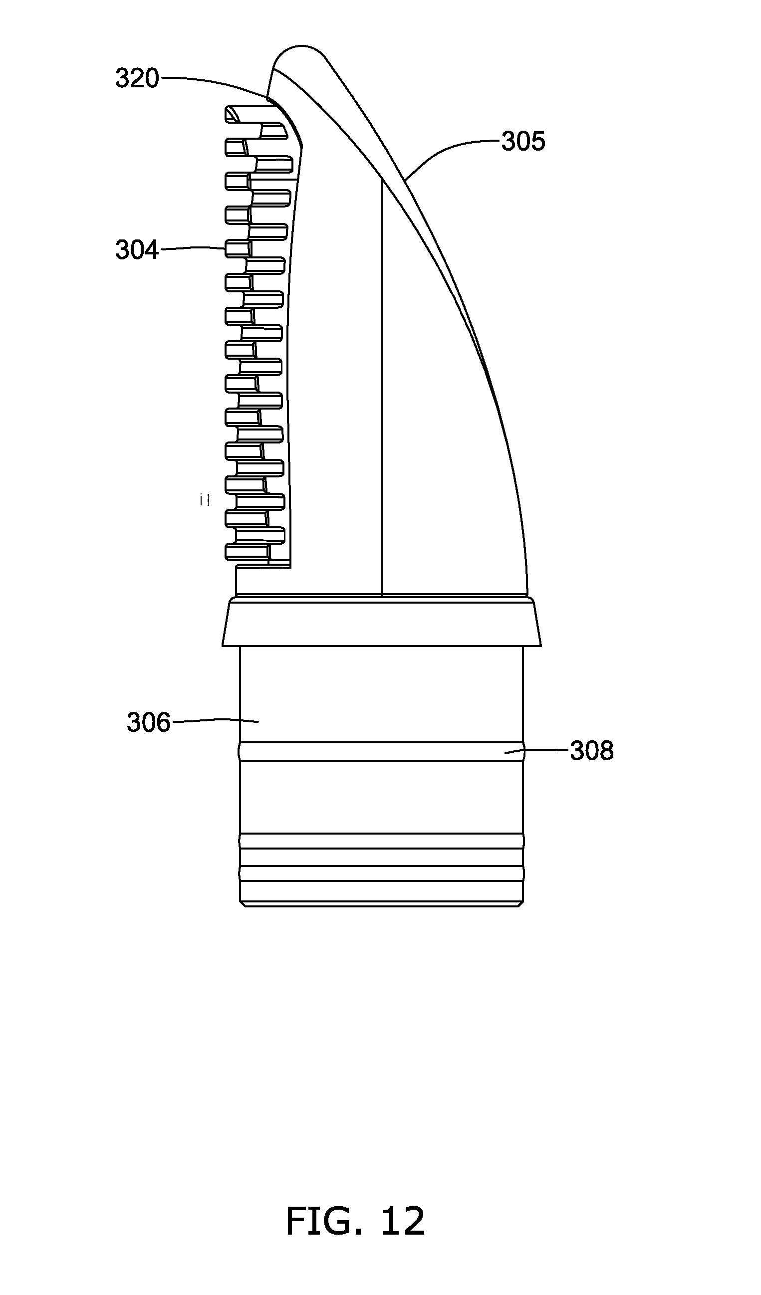
[0037] FIG. 12 is a side view of the cosmetic applicator tip of FIG. 11;
[0038] FIG. 13 is a side cross sectional view of the cosmetic applicator tip of FIG. 11; and
[0039] FIG. 14 is a front view of the cosmetic applicator tip of FIG. 11.
DETAILED DESCRIPTION
[0040] Conventional eyebrow gel applicators typically take the form of a cylindrical straight brush on the end of a stem or handle. The brush is inserted into a container holding the gel product, and the brush and container have the structure of a typical mascara applicator. These conventional brush applicators are stored in the product, and are withdrawn and re-inserted each time the product is used. The volume of product withdrawn with the brush is not readily adjusted, other than manually wiping the brush after it is withdrawn from the container. The repeated withdrawal and insertion of the brush into the container introduces air into the product which may degrade the product, and may introduce contaminants as well. The present inventors have identified a new and different cosmetic application device that allows for a variable amount of product to be dispensed, and prevents air and contaminants from entering the product container.
[0041] FIG. 1 shows an illustrative cosmetic application device configured to apply a product to the eyebrow area, and to then comb or brush the product through the eyebrow hairs, dispersing the product along individual hairs. The product may be a gel, cream, paste, liquid, or other product type suitable for being dispensed via an airless pump through an aperture. While the cosmetic application device is described herein as being used to apply a cosmetic product to the eyebrows, it will be understood that the device may also be used to apply a product to hair on other parts of the body, and the product may include a coloring agent. For example, the application device may be used to apply a gel and/or coloring agent to a mustache or beard.
[0042] The cosmetic application device 5 shown in FIG. 1 includes a housing 10, an actuator 20 for actuating an internal dispensing mechanism, and an applicator tip 200. The applicator tip 200 has an orifice 202 for dispensing product and a brush including a plurality of bristles 204 for distributing the product. In the example shown in FIGS. 2 and 3, the internal dispensing mechanism is an airless pump. The term airless pump refers to a pump that provides dispensing of a product from a container without permitting reverse (intake) flow of air via the pump. That is, as product is pumped from the container, the pumped product is not replaced with a corresponding volume of air through the pump. In addition to preventing reverse intake flow of air, an airless pump typically does not allow intake of any other substances to replace the volume of product pumped out of the container. For example, an airless pump may include a one-way valve, such as a check valve.
[0043] FIGS. 2 and 3 show the components of an exemplary airless pump mechanism, which is disposed inside the housing 10. The applicator tip 200 has been removed for clarity. The housing 10 has an open top 12 for receiving the applicator tip 200, and an open bottom 14 for receiving the airless pump mechanism. The pump mechanism may include an actuator 20, an inner tube 30, a crank shaft 40, a rotating nut 70, a spring press 80, a thrust collar 50, and a plunger 90. A jack screw 60 may extend within and connect the actuator 20, crank shaft 40, rotating nut 70, spring press 80, thrust collar 50, and plunger 90, as shown in FIG. 3. The pump mechanism is positioned within the housing beneath the product chamber 16, with the plunger 90 forming the bottom of the product chamber 16. When the airless pump is activated (e.g., by depressing or rotating the actuator 20 on the bottom portion of the pump), the plunger is advanced by the jack screw 60 into the chamber 16, forcing the cosmetic product from the product chamber 16 up through the neck portion 13 of the housing 10 and into the applicator tip 200 (FIG. 1, for example) for dispensing through the orifice 202 (FIG. 1, for example).
[0044] The user may dispense product from the housing 10 by rotating the actuator 20 in a clockwise or counter-clockwise direction. In some examples, the actuator 20 may have a plurality of defined stops so that rotation occurs between clicks, where each click rotates the actuator 20 a defined circumferential distance and corresponds to a defined amount of product being dispensed. In other examples, the actuator 20 may be a push button that is pressed upwards into the housing 10 to activate the airless pump. The actuator 20 may be configured to be pushed up a defined distance and may have a plurality of stops or clicks, each configured to dispense a defined amount of product. Alternatively, the user may push the actuator 20 upwards into the housing 10 a number of times to dispense more product.
[0045] The housing 10 may be a rigid container such as a glass or hard plastic bottle, with the airless pump mechanism providing the force needed to dispense the product. Another example delivery mechanism for dispensing the product may be a squeeze operation. The housing 10 may be a squeezable tube, bottle, or tottle (combination of tube and bottle common in the cosmetics industry), with or without an interior pump mechanism. In certain embodiments wherein the delivery mechanism is a squeeze operation, when pressure is applied to a housing containing a reservoir, the product in the reservoir may be forced, by the squeezing action, through the orifice 202 in the applicator tip 200 for application to the user's eyebrow area.
[0046] In yet another example, a delivery mechanism for dispensing the product may be by a pressurized dispenser, such as an aerosol dispenser. In certain embodiments wherein the delivery mechanism is an aerosol delivery mechanism, the composition will be held under pressure in a container and will be dispersed along with an aerosol propellant in response to actuation by a user. Actuation may be by depressing, rotating, tilting, or otherwise manipulating the applicator tip, pressing a button, and/or by any other suitable dispensing mechanism. Details of the construction and propellant of an aerosol dispenser are within the skill of one of ordinary skill in the art and will, therefore, not be described in detail herein.
[0047] FIGS. 4-14 illustrate three different applicator tip structures 100, 200, 300. FIGS. 4-7 illustrate an applicator tip 200 with an orifice 202 disposed on an application surface 205 of the applicator body 201 and a plurality of bristles 204 attached to a side surface 220 of the applicator body 201. In this example, the brush includes a central twisted wire core 210 containing a plurality of bristles 204. The wire core 210 is a twisted wire core typically made by forming a soft metal wire into a "U" shape. A plurality of bristles 204 are placed between the segments of wire, which are then twisted about the longitudinal axis to clamp bristles 204 at approximately a midpoints of the bristles 204. The bristle ends extend radially outward from the twisted wire core 210 in a semi-circular pattern, as shown in FIGS. 5 and 6.
[0048] The wire core 210 may be inserted into a vertical cutout region 207 extending between a top region 212 and a base 206 of the applicator body 201. The brush may be held in place by an extension of the wire core 210 without bristles fitting into an upper hole 214 in the top region 212 and a lower hole 216 in the base 206 of the applicator body 201. The cutout region 207 may extend along a side surface 220 of the applicator body 201. As shown in FIG. 7, the applicator tip 200 may have a channel 203 extending longitudinally from the orifice 202 in the application surface 205 to an opening in the base 206 such that when the applicator tip 200 is inserted into the neck portion 13 of the housing 10, the channel 203 is in fluid communication with the product chamber 16. The channel 203 may be formed with the applicator body 201, or it may be a separate tube formed of a different material from the applicator body 201, and inserted into the applicator body 201. The application surface 205 is spaced apart from the side surface 220 such that product expelled through the orifice 202 does not contact the bristles 204. This structure allows for the product to be applied directly to the eyebrow area, and then the bristles 204 may be used to comb and shape the eyebrow. The orifice 202 may be substantially centered within the applicator body 201 when viewed from the top as shown in FIG. 6. In other examples, the orifice 202 may be positioned off-center relative to the applicator body 201.
[0049] FIGS. 8-10 illustrate another example of an applicator tip 100 with an orifice 102 disposed on an application surface 105 of the applicator body 101 and a plurality of bristles 104 attached to a side surface 120 of the applicator body 101. The application surface 105 is spaced apart from the side surface 120 such that product expelled through the orifice 102 does not contact the bristles 104. The application surface 105 may be disposed on the top surface of the applicator tip 100, with the bristles 104 extending radially outward from the side surface 120, as shown in FIG. 9. The orifice 102 may be substantially centered within the applicator body 101 when viewed from the top as shown in FIG. 10. In other examples, the orifice 102 may be positioned off-center relative to the applicator body 101. As shown in FIG. 8, clusters of bristles 104 may be attached in a plurality of rows extending longitudinally along the side of the applicator body 101. The bristles 104 may be attached directly to the applicator body 101, such as by being embedded in the side surface 130, as shown in FIG. 9. Similar to the applicator tip 200 shown in FIGS. 4-7, the applicator tip 100 may have a channel 103 extending longitudinally from the orifice 102 in the application surface 105 to the base 106. In some examples, the applicator body 101 may have a monolithic construction with the bristles 104 attached, such as with adhesive, after forming the applicator body 101. Alternatively, the bristles 104 may be molded onto the applicator body 101.
[0050] FIGS. 11-14 illustrate an applicator tip 300 in which the applicator brush includes a plurality of ridges or protrusions 304 extending radially outward from a side surface 320 of the applicator body 301. The applicator tip 300 has an orifice 302 disposed on an application surface 305 of the applicator body 301. Applicator tip 300 has a channel 303 extending longitudinally from an orifice 302 in the application surface 305 to an opening in the base 306. The side surface 320 with protrusions 304 extending radially outward therefrom may be substantially opposite the application surface 305, as shown in FIGS. 11 and 13. The application surface 305 is spaced apart from the side surface 320 such that product expelled through the orifice 302 does not contact the protrusions 304. This structure allows for the product to be applied directly to the eyebrow area, and then the protrusions 304 may be used to comb and shape the eyebrow.
[0051] The protrusions 304 may be formed from the same material as the applicator body 301, such as by molding. Alternatively, the protrusions 304 may be formed from a different material and attached to a recess in the side surface 320 of the applicator body 301. The protrusions 304 may be formed from thermoplastic elastomer (TPE) to provide a soft, flexible surface. The protrusions 304 may be a plurality of vertically spaced apart horizontal ridges, as shown in FIGS. 12 and 14, or they may have other geometries including but not limited to vertical protrusions, wavy ridges, semi-circular ridges, etc. The protrusions 304 may extend less than halfway around the circumference of the applicator tip 300, as shown in FIGS. 12 and 14. In other examples, the protrusions 304 may extend more than halfway round the applicator tip 300, but do not intersect the application surface 305. In some embodiments, either the protrusions 304 or the applicator tip 300 may be made of metal.
[0052] In some examples, any of the applicator tips 100, 200, 300 may include a collar 330, as shown in FIG. 13, which forms the base 306 and includes ridges 308 for connecting to the neck portion 13 of the housing 10 (FIGS. 2-3). A check valve to prevent backflow of product and/or ingress of air or contaminants may be provided inside of the collar 330.
[0053] The applicator tip 100, 200, 300 may be affixed to the housing 10 by, for example, a snap fit or any other known attachment including adhesive, screw, heat welding, etc. The applicator tip 100, 200, 300 may include various features which allow it to be affixed to the housing 10. Alternatively, these features may be designed to allow the applicator tip 100, 200, 300 to be removed by an end user, allowing the product chamber 16 in the housing 10 to be refilled with additional cosmetic product or even replaced. The applicator tip 100, 200, 300 is illustrated as having a base 106, 206, 306 configured to be received inside the neck portion 13 of the housing 10. For example, one or more grooves 18 may be present on an inner surface of the neck portion 13 of the housing 10, as shown in FIG. 3. The grooves 18 may be configured to receive one or more ridges 108, 208, 308 disposed on the outer surface of the base 106, 206, 306 of the applicator tip 100, 200, 300, as shown in FIGS. 4, 8, and 11. The base 106, 206, 306 of the applicator tip 100, 200, 300 may be inserted into the neck portion 13 of the housing 10 to engage the housing 10 in a snap or friction fit.
[0054] In other examples, a screw-type mechanism may be used, with base 106, 206, 306 of the applicator tip 100, 200, 300 including threads on its exterior portion designed to be received by threads on the interior of the neck portion 13 of the housing 10. Alternative structures for attaching the applicator tip 100, 200, 300 to the housing 10 include crimping, adhesive, press-fit, snap-fit, retaining ribs or barbs on the outside of the applicator tip 100, 200, 300 and/or the inside of the neck portion 13 of the housing, and/or by any other suitable attachment means.
[0055] While the cosmetic application devices 5 shown in the figures are comprised of a separate applicator tip 100, 200, 300 and housing 10, in other implementations, and to decrease manufacturing costs, or for any other desired reason, some or all of the applicator tip and some or all of the housing may be formed as a monolithic structure.
[0056] The cosmetic application device 5 may also include a cap (not shown) that encapsulates the applicator tip 100 when the device is not in use. The neck portion 13 of the housing 10 may include a structure, such as groove 19, to engage the cap in a snap fit or friction fit. Alternatively the outer surface of the neck portion 13 may be threaded to engage a threaded cap.
[0057] In any of the exemplary applicator tips 100, 200, 300, the application surface 105, 205, 305 may be angled relative to the longitudinal axis L-L of the applicator tip 100, 200, 300, as shown in FIGS. 4, 9, and 12. This may aid in applying the product to the eyebrow area. In other examples, the application surface 105, 205, 305 may be perpendicular to the longitudinal axis. The application surface 105, 205, 305 may have a cross-sectional shape that generally resembles a tear drop, as shown in FIGS. 6, 10, and 11. However, the application surface 105, 205, 305 may take any cross-sectional shape desired, such as, but not limited to, circular, ovoid, square, rectangular, polygonal, etc. In some examples, the cross-section of the applicator tip 100, 200, 300 may generally increase in size from the application surface 105, 205, 305 to the base 106, 206, 306. The cross-sectional shape may change, such as from the teardrop shape of the application surface 105, 205, 305 to the circular base 106, 206, 306, as shown in FIGS. 6, 10, and 11. The change in size and/or shape may be gradual, sloping, abrupt, or step-wise, as desired. The reverse configuration is also contemplated. The cross-sectional size and shape of the application tip may also remain constant or substantially constant along a length thereof.
[0058] The housing 10 and applicator body 101, 201, 301 as shown and described above may be made of any suitable material such as, for example, thermoplastic elastomer (TPE), low density polyethylene (LDPE), synthetic polymer, partially of a resin such as, for example, acrylonitrile butadiene styrene (ABS), styrene acrylonitrile (SAN), pentachlorothioanisole (PCTA), polypropylene (PP), polyethylene (PE), polyurethane, rubber, silicone, nylon, ceramic, glass, metal, or composite material, and/or combinations thereof. Moreover, various elements may be made of any combination of substantially clear, substantially opaque, and/or translucent materials. Natural materials as wood, stone or leather may be used as well for decorative or other purposes.
[0059] The applicator bristles 104, 204 and protrusions 304 may be formed in part or in whole from various materials. In addition to allowing the user to comb or brush hair, such as the eyebrows, the applicator bristles 104, 204 and protrusions 304 may be made of a material configured to provide the user with a tactile experience. Some example materials, may include, but are not limited to a thermoplastic elastomer (TPE) material, silicone, metals, ceramics, stone, rubber, etc. Additional materials may include, but are not limited to natural bristles (hair, cellulose fibers, cotton, hemp, flax or composites thereof), synthetic bristles (e.g. plastic, silicone, latex or composites thereof), or composites thereof. Magnetic bristles may be used, if desired.
[0060] For the following defined terms, these definitions shall be applied, unless a different definition is given in the claims or elsewhere in this specification. In this document, the terms "a" or "an" are used, as is common in patent documents, to include one or more than one, independent of any other instances or usages of "at least one" or "one or more" unless the content clearly dictates otherwise. Moreover, in the following claims, the terms "first," "second," and "third," etc. are used merely as labels, and are not intended to impose numerical requirements on their objects. The above description is intended to be illustrative, and not restrictive.
[0061] As used in the above description and the appended claims, the term "or" is generally employed in its sense including "and/or" unless the content clearly dictates otherwise.
[0062] Relative terms such as "front", "back", "side", "top", "bottom", variants thereof, and the like, may be generally be considered with respect to the positioning, direction, and/or operation of various elements relative to a user and/or other components of the device. It is to be understood that relative terms are not intended to be limiting and are only exemplary.
[0063] The above detailed description should be read with reference to the drawings in which similar elements in different drawings are numbered the same. The drawings, which are not necessarily to scale, show, by way of illustration, specific embodiments in which the invention can be practiced. These embodiments are also referred to herein as "examples." Such examples can include elements in addition to those shown or described. However, the present inventors also contemplate examples in which only those elements shown or described are provided. Moreover, the present inventors also contemplate examples using any combination or permutation of those elements shown or described (or one or more aspects thereof), either with respect to a particular example (or one or more aspects thereof), or with respect to other examples (or one or more aspects thereof) shown or described herein. For example, the above examples (or one or more aspects thereof) may be used in combination with each other. Other embodiments can be used, such as by one of ordinary skill in the art upon reviewing the above description.
[0064] Although the invention has been described in language specific to structural features and/or methodological acts, it is to be understood that the invention is not necessarily limited to the specific features or acts described. Rather, the specific features and acts are disclosed as illustrative forms of implementing the invention.
* * * * *
D00000
D00001
D00002
D00003
D00004
D00005
D00006
D00007
D00008
D00009
D00010
D00011
D00012
D00013

D00014

XML
uspto.report is an independent third-party trademark research tool that is not affiliated, endorsed, or sponsored by the United States Patent and Trademark Office (USPTO) or any other governmental organization. The information provided by uspto.report is based on publicly available data at the time of writing and is intended for informational purposes only.
While we strive to provide accurate and up-to-date information, we do not guarantee the accuracy, completeness, reliability, or suitability of the information displayed on this site. The use of this site is at your own risk. Any reliance you place on such information is therefore strictly at your own risk.
All official trademark data, including owner information, should be verified by visiting the official USPTO website at www.uspto.gov. This site is not intended to replace professional legal advice and should not be used as a substitute for consulting with a legal professional who is knowledgeable about trademark law.