Sulfur Nanosponge Cathode For Lithium-sulfur Battery And Methods Of Manufacture Thereof
NIU; Junjie ; et al.
U.S. patent application number 16/027924 was filed with the patent office on 2019-01-03 for sulfur nanosponge cathode for lithium-sulfur battery and methods of manufacture thereof. The applicant listed for this patent is Massachusetts Institute of Technology. Invention is credited to Akihiro KUSHIMA, Ju LI, Junjie NIU, Chao WANG.
| Application Number | 20190006663 16/027924 |
| Document ID | / |
| Family ID | 55631251 |
| Filed Date | 2019-01-03 |


View All Diagrams
| United States Patent Application | 20190006663 |
| Kind Code | A1 |
| NIU; Junjie ; et al. | January 3, 2019 |
SULFUR NANOSPONGE CATHODE FOR LITHIUM-SULFUR BATTERY AND METHODS OF MANUFACTURE THEREOF
Abstract
The present invention is directed to lithium-sulfur batteries exhibiting a high capacity, high cycle life with low production cost and improved safety.
| Inventors: | NIU; Junjie; (Malden, MA) ; KUSHIMA; Akihiro; (Arlington, MA) ; WANG; Chao; (Cambridge, MA) ; LI; Ju; (Weston, MA) | ||||||||||
| Applicant: |
|
||||||||||
|---|---|---|---|---|---|---|---|---|---|---|---|
| Family ID: | 55631251 | ||||||||||
| Appl. No.: | 16/027924 | ||||||||||
| Filed: | July 5, 2018 |
Related U.S. Patent Documents
| Application Number | Filing Date | Patent Number | ||
|---|---|---|---|---|
| 14853610 | Sep 14, 2015 | 10033034 | ||
| 16027924 | ||||
| 62049685 | Sep 12, 2014 | |||
| Current U.S. Class: | 1/1 |
| Current CPC Class: | H01M 4/587 20130101; Y02T 10/70 20130101; H01M 4/386 20130101; H01M 4/366 20130101; H01M 4/624 20130101; H01M 2004/028 20130101; H01M 2300/0028 20130101; H01M 4/0402 20130101; H01M 2220/20 20130101; H01M 4/625 20130101; H01M 4/136 20130101; H01M 10/052 20130101; H01M 10/0569 20130101; H01M 10/0525 20130101; H01M 10/0568 20130101; Y02E 60/10 20130101; H01M 4/38 20130101; H01M 2220/30 20130101; H01M 4/387 20130101 |
| International Class: | H01M 4/36 20060101 H01M004/36; H01M 10/052 20100101 H01M010/052; H01M 4/136 20100101 H01M004/136; H01M 4/38 20060101 H01M004/38; H01M 10/0569 20100101 H01M010/0569; H01M 10/0568 20100101 H01M010/0568; H01M 10/0525 20100101 H01M010/0525; H01M 4/04 20060101 H01M004/04; H01M 4/62 20060101 H01M004/62; H01M 4/587 20100101 H01M004/587 |
Goverment Interests
GOVERNMENT SUPPORT
[0002] This invention was made with government support under Contract No. FA9550-08-1-0325 awarded by the U.S. Air Force and Contract No. DMR-1120901 awarded by the National Science Foundation. The government has certain rights in the invention.
Claims
1. A cathode comprising a nanostructured sponge having a sulfur-covering-carbon structure prepared by a method comprising: functionalizing the surface of conductive carbon black particles, thereby forming hydroxyl and/or carboxyl groups on the surface of the conductive carbon black particles; dispersing a mixture comprising sulfur particles and at least one surfactant in a matrix of the functionalized conductive carbon black particles; and heating the dispersed sulfur particles and functionalized conductive carbon black particles for a time and to a temperature above the melting point of sulfur, whereby the sulfur forms a coating over the functionalized conductive carbon black particles to form the nanostructured sponge having the sulfur-covering-carbon structure.
2. The cathode of claim 1, comprising sulfur-carbon clusters smaller than about 10 .mu.m.
3. A lithium battery comprising an anode, the cathode of claim 1, and an electrolyte.
4. The lithium battery of claim 3, wherein the anode is selected from the group consisting of carbon, silicon, silicon/carbon composite, lithium titanate, and tin cobalt alloy.
5. The lithium battery of claim 3, wherein the electrolyte is selected from the group consisting of electrolyte containing lithium salts and combination of linear and cyclic carbonates.
6. A nanostructured sponge cathode comprising: a conductive carbon black matrix and sulfur, wherein the sulfur is disposed over the conductive carbon black particles to provide a sulfur-over-carbon structure.
7. The nanostructured sponge cathode of claim 6, wherein the particle size of said conductive carbon black particles ranges from 80 nm to 800 nm.
8. The nanostructured sponge cathode of claim 6, wherein the sulfur is substantially amorphous.
9. The nanostructured sponge cathode of claim 6, further comprising a conductive polymer.
10. The nanostructured sponge cathode of claim 9, wherein the conductive polymer comprises polypyrrole.
11. The nanostructured sponge cathode of claim 6, wherein the amount of sulfur ranges from about 50 to about 70 wt. %.
Description
CROSS-REFERENCE TO RELATED APPLICATION(S)
[0001] This application is a divisional application of U.S. application Ser. No. 14/853,610, filed Sep. 14, 2015, and entitled "SULFUR NANOSPONGE CATHODE FOR LITHIUM-SULFUR BATTERY AND METHODS OF MANUFACTURE THEREOF," which claims the benefit under 35 U.S.C. .sctn. 119(e) of U.S. Application No. 62/049,685, entitled "Scalable Synthesis of Sulfur Nanosponge Cathode for Lithium-Sulfur Battery with Greatly Improved Cyclability," and filed on Sep. 12, 2014, which application is hereby incorporated by reference herein.
BACKGROUND
[0003] The surging demand for rechargeable batteries in portable electronics and electric vehicles has stimulated extensive studies on various lithium-based electrode materials. Sulfur is a well-researched material that is nontoxic to the environment and earth-abundant. It can host two lithium ions (Li.sup.+) non-topotactically, and exhibits a high theoretical capacity of 1675 mAh/g, almost 10 times that of commercially popular transition metal based intercalating cathode materials, such as LiCoO.sub.2. In terms of gravimetric energy density, at 2.1 V versus Li/Li.sup.+, lithium-sulfur (Li--S) batteries possess about 5 times the energy density compared to those based on LiCoO.sub.2.
[0004] However, sulfur and its insoluble by-product compounds, such as Li.sub.2S.sub.2 and Li.sub.2S, are poor electronic and ionic conductors (electronic insulators), which significantly reduces the effectiveness of Li--S batteries. Furthermore, these deficiencies necessitate positioning sulfur-based electrodes in constant and intimate contact with liquid electrolyte to enhance effective Li.sup.+ conductivity, which otherwise leads to a rapid degradation of capacity and cycle life. In addition, the capacity of conventional Li--S batteries rapidly decay with the number of charge/discharge cycles due to rapid dissolution of soluble lithium polysulfides Li.sub.2S.sub.x (4.ltoreq.x.ltoreq.8) into interfacial bulk liquid electrolyte, and/or via volume expansion-induced mechanical failures within the electrode structures that couple with and led to degrading electronic conductivity across the electrode. To retard the loss of S into the electrolyte solution, many strategies have been proposed and undertaken, such as modifying the electrolyte to be a poorer solvent for sulfur species, and engineering a better electrode and operating voltage of the electrochemical system, as described, for example, in the articles by Z. Lin, Z. C. Liu, W. J. Fu, N. J. Dudney and C. D. Liang, in Angewandte Chemie International Edition, 2013, 52, 7460-7463; by E. Peled, Y. Sternberg, A. Gorenshtein and Y. Lavi, in the Journal of the Electrochemical Society, 1989, 136, 1621-1625; by S. E. Cheon, K. S. Ko, J. H. Cho, S. W. Kim, E. Y. Chin and H. T. Kim, in the Journal of the Electrochemical Society, 2003, 150, A800-A805; by L. X. Yuan, J. K. Feng, X. P. Ai, Y. L. Cao, S. L. Chen and H. X. Yang, in Electrochemistry Communications, 2006, 8, 610-614; by J. H. Shin and E. J. Cairns, in the Journal of Power Sources, 2008, 177, 537-545; by Z. W. Seh, W. Li, J. J. Cha, G. Zheng, Y. Yang, M. T. McDowell, P.-C. Hsu and Y. Cui, in Nature Communications, 2013, 4, 6; by J. Wang, S. Y. Chew, Z. W. Zhao, S. Ashraf, D. Wexler, J. Chen, S. H. Ng, S. L. Chou and H. K. Liu, in Carbon, 2008, 46, 229-235; and by Y. S. Su, Y. Z. Fu, T. Cochell and A. Manthiram, in Nature Communications, 2013, 4, 2985. `Solvent-in-Salt` electrolytes with ultrahigh salt concentration can also be used to achieve a high-energy rechargeable battery, for example as described in the articles by L. M. Suo, Y. S. Hu, H. Li, M. Armand and L. Q. Chen, in Nature Communications, 2013, 4; and by Y. Sun, L. Zhao, H. L. Pan, X. Lu, L. Gu, Y. S. Hu, H. Li, M. Armand, Y. Ikuhara, L. Q. Chen and X. J. Huang, in Nature Communications, 2013, 4. Strategies for inhibiting undesirable polysulfide dissolution reactions via modifying the charging condition were developed to obtain improved cycle life (>500 cycles), and additives like graphene, mesoporous carbon, and conductive polymers were exploited to facilitate efficient electron conduction, as described in the articles by H. L. Wang, Y. Yang, Y. Y. Liang, J. T. Robinson, Y. G. Li, A. Jackson, Y. Cui and H. J. Dai, in Nano Letters, 2011, 11, 2644-2647; by M. K. Song, Y. G. Zhang and E. J. Cairns, in Nano Letters, 2013, 13, 5891-5899; by N. Jayaprakash, J. Shen, S. S. Moganty, A. Corona and L. A. Archer, in Angewandte Chemie International Edition, 2011, 50, 5904-5908; by Y. Z. Fu and A. Manthiram, in the Royal Society of Chemistry Advances, 2012, 2, 5927-5929; by X. Liang, Y. Liu, Z. Y. Wen, L. Z. Huang, X. Y. Wang and H. Zhang, in the Journal of Power Sources, 2011, 196, 6951-6955; by H. K. Song and G. T. R. Palmore, in Advanced Materials, 2006, 18, 1764; by J. L. Wang, J. Yang, J. Y. Xie and N. X. Xu, in Advanced Materials, 2002, 14, 963; and by Y. Yao, N. Liu, M. T. McDowell, M. Pasta and Y. Cui, in Energy & Environmental Science, 2012, 5, 7927. By encapsulating sulfur in TiO.sub.2 nanoshells with pre-existing void, the .about.80% volume expansion of sulfur in lithiation can be accommodated and this yolk-shell structure can also restrict the intermediate polysulfides to reside within the structure, so the battery could run over 1000 cycles with good capacity retention, as described in Z. W. Seh, W. Li, J. J. Cha, G. Zheng, Y. Yang, M. T. McDowell, P.-C. Hsu and Y. Cui, in Nature Communications, 2013, 4, 6. However, although recent technological progress has been made in Li--S battery performance according to G. Y. Zheng, Y. Yang, J. J. Cha, S. S. Hong and Y. Cui, in Nano Letters, 2011, 11, 4462-4467, manufacturing such improved Li--S battery system at mass-production levels, employing a scalable and cost-effective synthesis is still yet to be demonstrated, until the present invention.
SUMMARY
[0005] In some embodiments described herein, a method of manufacturing is disclosed comprising functionalizing the surface of conductive carbon black particles, thereby forming hydroxyl and/or carboxyl groups on the surface of the conductive carbon black particles, dispersing a mixture comprising sulfur particles, and at least one surfactant in a matrix of the functionalized conductive carbon black particles, and heating the dispersed sulfur particles and functionalized conductive carbon black particles for a time and to a temperature above the melting point of sulfur, whereby the sulfur forms a coating over the functionalized conductive carbon black particles to form a nanostructured sponge having a sulfur-covering-carbon structure. In another embodiment, the method of functionalizing comprises contacting the conductive carbon black particles with acid. In another embodiment, the sulfur particles are formed in-situ in the functionalized conductive carbon black by reducing a water-soluble sulfur-containing compound. In another embodiment, heating is at a temperature ranging from about 150 to about 200.degree. C. In another embodiment, the sulfur coating is no thicker than 1 micron. In another embodiment, the method of heating is carried out for a time ranging from about 2 to about 50 hours. In another embodiment, the conductive carbon black particles have a BET surface area ranging from about 40 m.sup.2/g to about 80 m.sup.2/g. In another embodiment, the method of dispersing comprises agitating in an aqueous solution, conductive carbon black particles, an acid, a surfactant and thiosulfate, whereby the thiosulfate forms sulfur particles and the conductive carbon black particles are surface functionalized in situ. In other embodiments, the method further comprises isolating and drying the mixture of functionalized conductive carbon black particles and sulfur particles. In another embodiment, a cathode comprises a nanostructured sponge having a sulfur-covering-carbon structure prepared by the methods disclosed herein. In some embodiments, a lithium battery comprises an anode, the cathode as prepared by the methods described herein, and an electrolyte. In another embodiment, the lithium battery contains an anode selected from the group consisting of carbon (graphite, graphene, hard carbon, mesoporous carbon, etc. and any combination thereof), silicon, silicon/carbon composite, lithium titanate (LTO, Li.sub.4Ti.sub.5O.sub.12, etc.), and tin cobalt alloy. In another embodiment, the lithium battery contains an electrolyte selected from the group consisting of electrolyte containing lithium salts (e.g., LiPF.sub.6, LiBF.sub.4 or LiClO.sub.4) and combinations of linear and cyclic carbonates (e.g., ethylene carbonate, dimethyl carbonate or poly(oxyethylene)).
[0006] In some other embodiments, a nanostructured sponge cathode is disclosed which comprises a conductive carbon black matrix and sulfur, wherein the sulfur is disposed over the conductive carbon black particles to provide a sulfur-over-carbon structure. In another embodiment, the nanostructured sponge cathode contains the particle size of said conductive carbon black particles ranges from 80 nm to 800 nm. In another embodiment, the sulfur of the nanostructured sponge cathode is substantially amorphous. In another embodiment, the nanostructured sponge cathode comprises a conductive polymer. In another embodiment, the nanostructured sponge cathode includes the conductive polymer comprising polypyrrole. In another embodiment, the nanostructured sponge cathode contains sulfur whose amount ranges from about 50 wt. % to about 70 wt. %. In another embodiment, the nanostructured sponge cathode comprises sulfur-carbon clusters smaller than about 10 .mu.m.
BRIEF DESCRIPTION OF THE DRAWINGS
[0007] The skilled artisan will understand that the drawings primarily are for illustrative purposes and are not intended to limit the scope of the inventive subject matter described herein. The drawings are not necessarily to scale; in some instances, various aspects of the inventive subject matter disclosed herein may be shown exaggerated or enlarged in the drawings to facilitate an understanding of different features. In the drawings, like reference characters generally refer to like features (e.g., functionally similar and/or structurally similar elements). All documents disclosed herein are incorporated by reference in the entirety for all purposes.
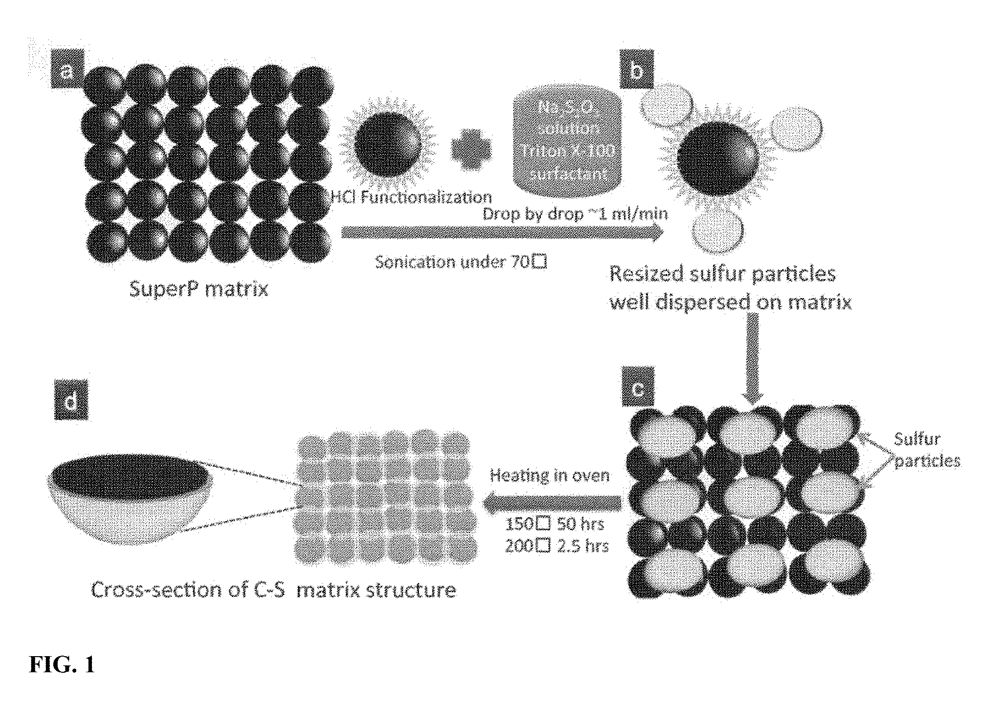
[0008] FIG. 1 is a schematic of manufacturing process flow for in-situ synthesis of sulfur nanosponge (SULFUN) cathode matrix.
[0009] FIG. 2 shows discharge voltage profiles of SULFUN (a) treated at 200.degree. C. with 2.5 hours with a charge rate of 0.2 C; cycling performance of commercial pure sulfur, mortar milled S/C mixture, and SULFUN treated at 200.degree. C. for 2.5 hours (b); and at 150.degree. C. for 50 hours (c) at a charge rate of 0.2 C.
[0010] FIG. 3 Comparable cycling performance of the pure sulfur and SULFUN matrix treated at 200.degree. C. for 2.5 hours at a rate of 0.2 C. The inset is the enlarged cycling profile. This sample was synthesized using the complete method as in FIG. 2b.
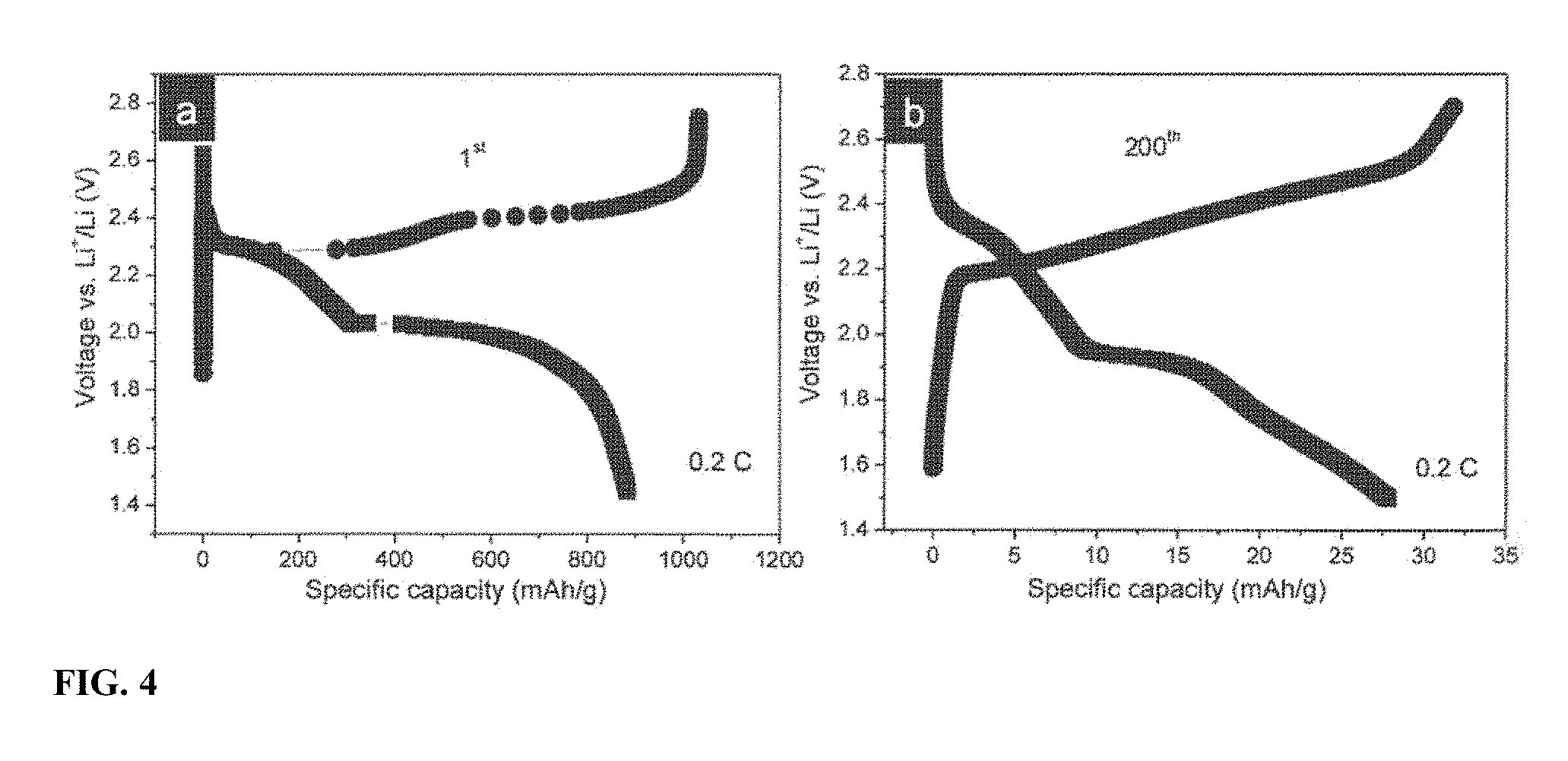
[0011] FIG. 4 Charge/discharge voltage profiles of the mortar milled S/C mixture coin cells after cycling at 0.2 C. The 1.sup.st a) and the 200.sup.th b) cycles.
[0012] FIG. 5 Charge/discharge voltage profiles of the SULFUN coin cells after cycling at 0.2 C. Samples annealed at 200.degree. C. a-b) and at 150.degree. C. c-d).
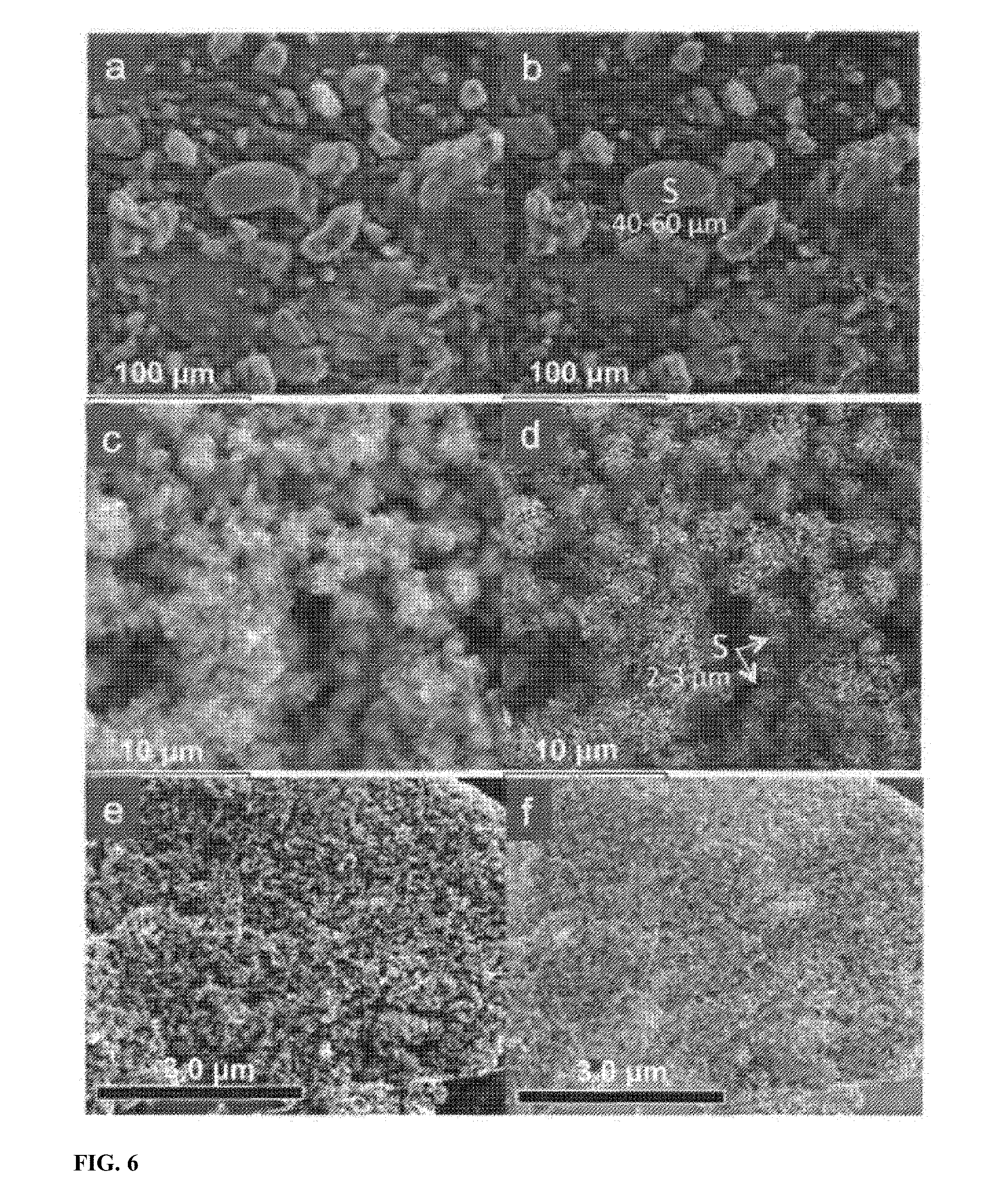
[0013] FIG. 6 are SEM images and the corresponding Energy-dispersive X-ray spectroscopy (EDS) mappings. SEM morphologies of the milled S/C mixture (a), before (c) and after (e) annealed at 200.degree. C. with 2.5 hours. (b), (d), and (f) are sulfur and carbon mappings of the areas shown in (a), (c), and (e), respectively.
[0014] FIG. 7 SEM imaging of as-synthesized pure sulfur without carbon a), SULFUN matrix treated at 150.degree. C. for 50 hours b), and 200.degree. C. for 2.5 hours c). Scale bar is 1 .mu.m.
[0015] FIG. 8 EDS maps and electron microscopy images of the SULFUN matrix. a) SEM morphology of the matrix annealed at 150.degree. C. with 50 hours. Carbon b) and sulfur c) mappings of the area shown in a). d) Sulfur and carbon mapping of as-received SULFUN matrix before heating. TEM imaging of the SULFUN before e) and after f) heating at 200.degree. C. with 2.5 hours. Scale bar in e) and f): 5 .mu.m.
[0016] FIG. 9 TGA profiles and DTA curves recorded in argon with a heating rate of 10.degree. C. min.sup.-1, for SULFUN matrices treated at 150.degree. C. with 50 hours a) and 200.degree. C. with 2.5 hours b), respectively.
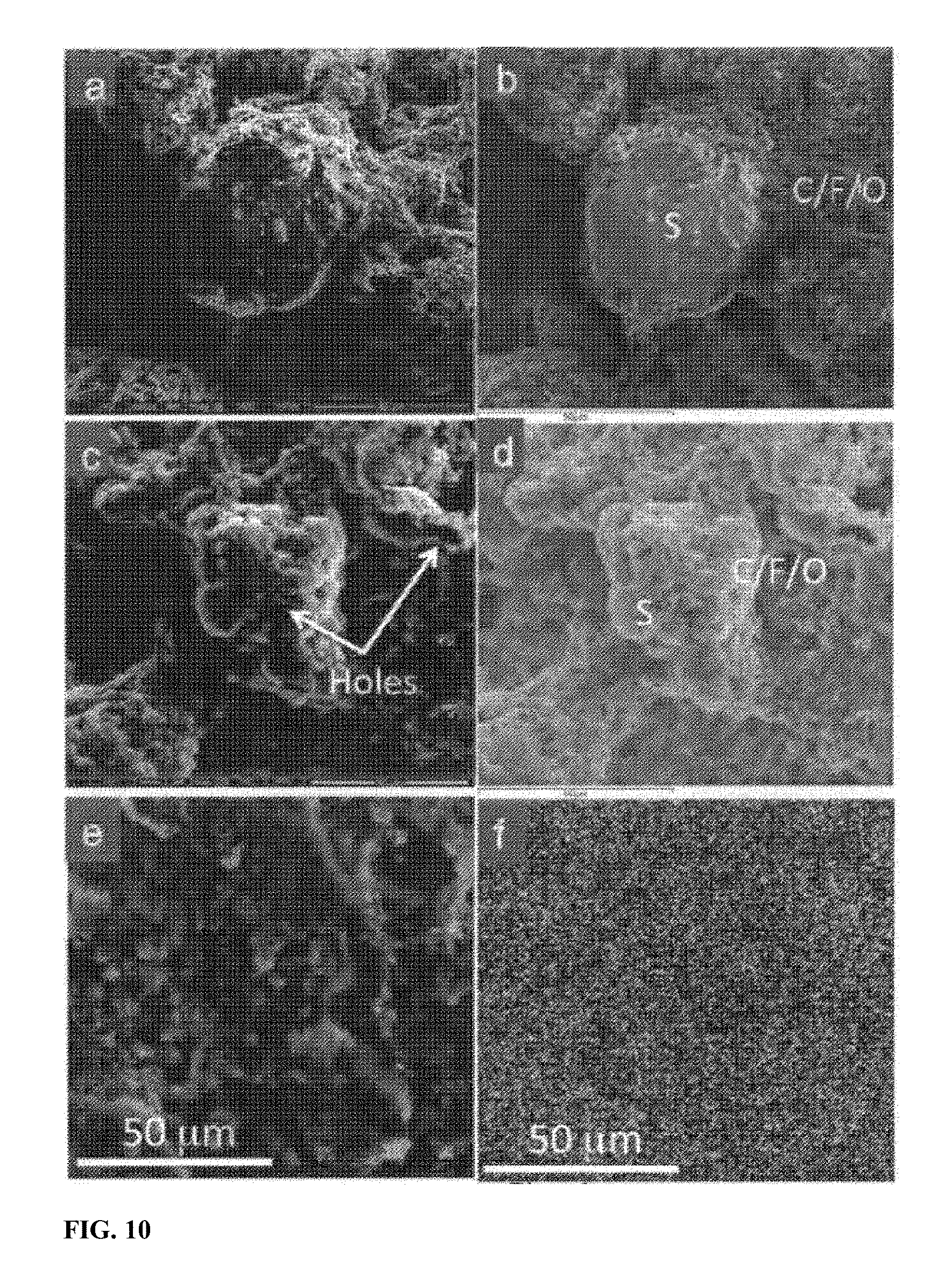
[0017] FIG. 10 shows morphological evolution of commercial sulfur particle and SULFUN during charge/discharge. SEM morphologies of the commercial sulfur mixture with Super P and binder before (a) and after two cycles (c). (b) and (d) are EDS Element maps of the areas shown in (a) and (c), respectively. (e) shows SEM morphology of the electrode made of SULFUN annealed at 200.degree. C. for 2.5 hours after two cycles with corresponding sulfur elemental maps (f).
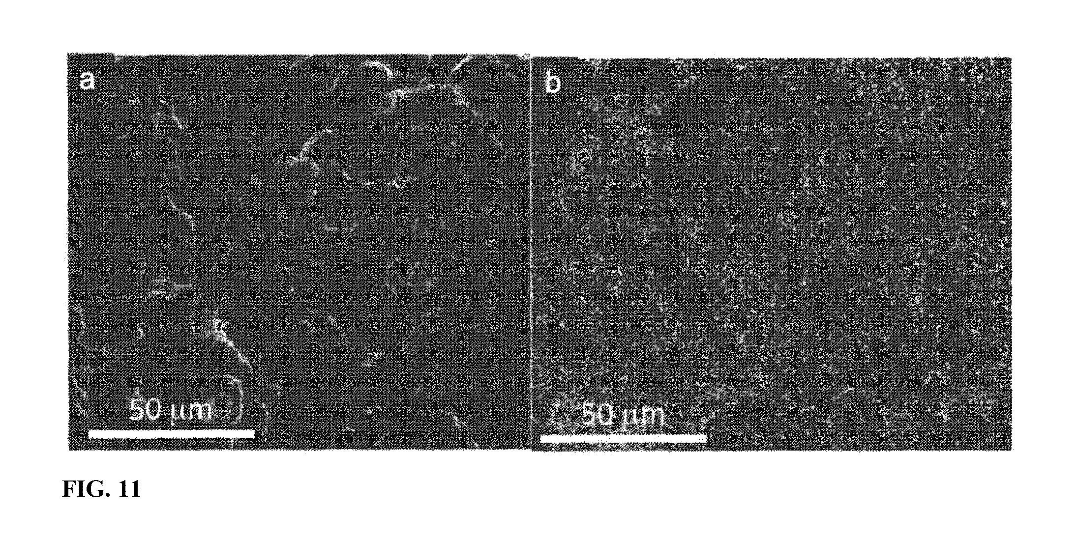
[0018] FIG. 11 SEM image and EDS maps of the commercial cathode electrode after running two cycles. a) SEM morphology of the electrode. b) The corresponding sulfur element map.
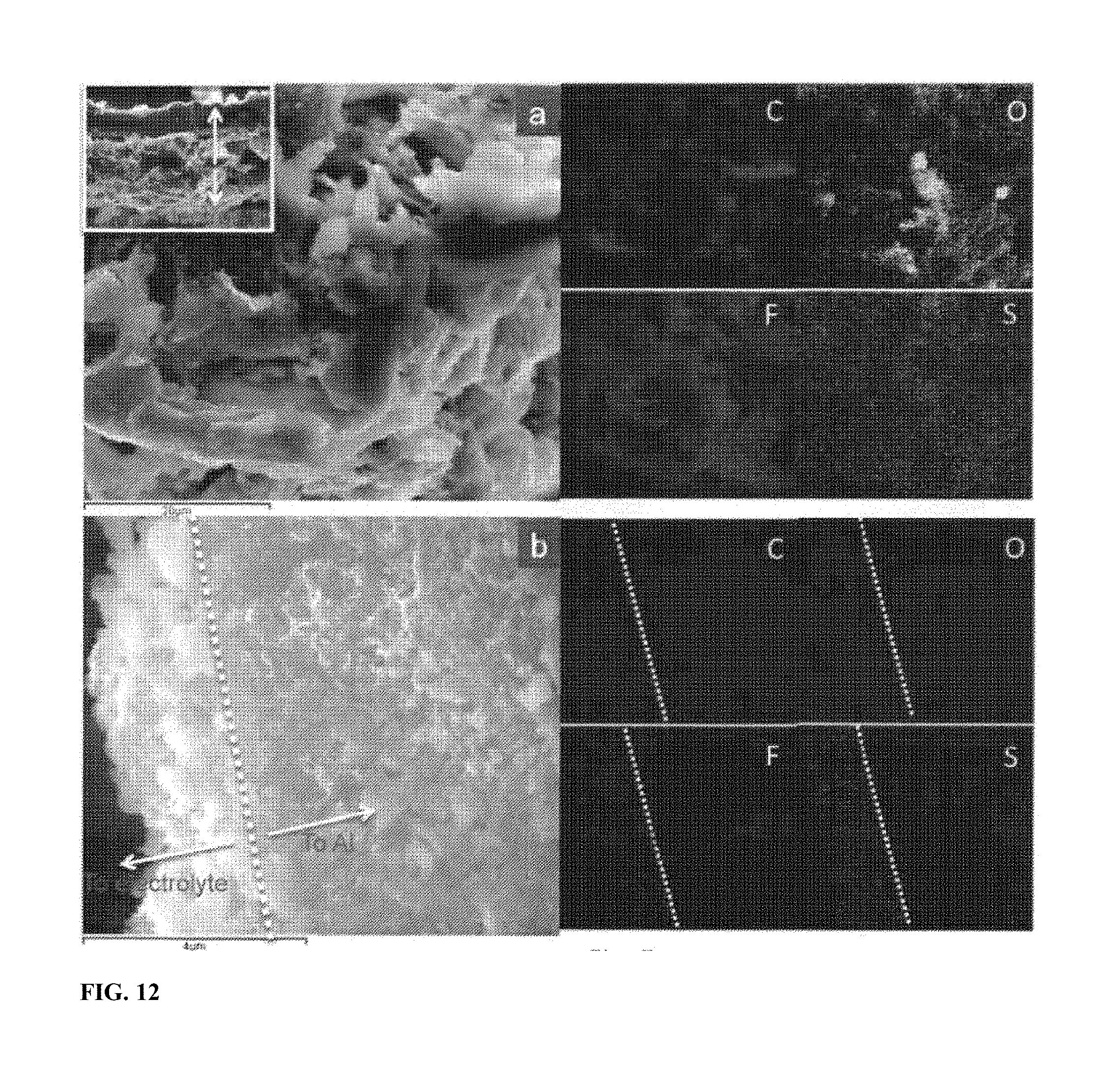
[0019] FIG. 12 shows cross-section images of the electrode after two charge/discharge cycles. SEM images and the corresponding EDS elemental maps of the cross-section of the electrode made of commercial sulfur (a) and SULFUN (b). The elemental map data indicate that the electrolyte was suppressed by the SULFUN surface instead of the commercial sulfur.
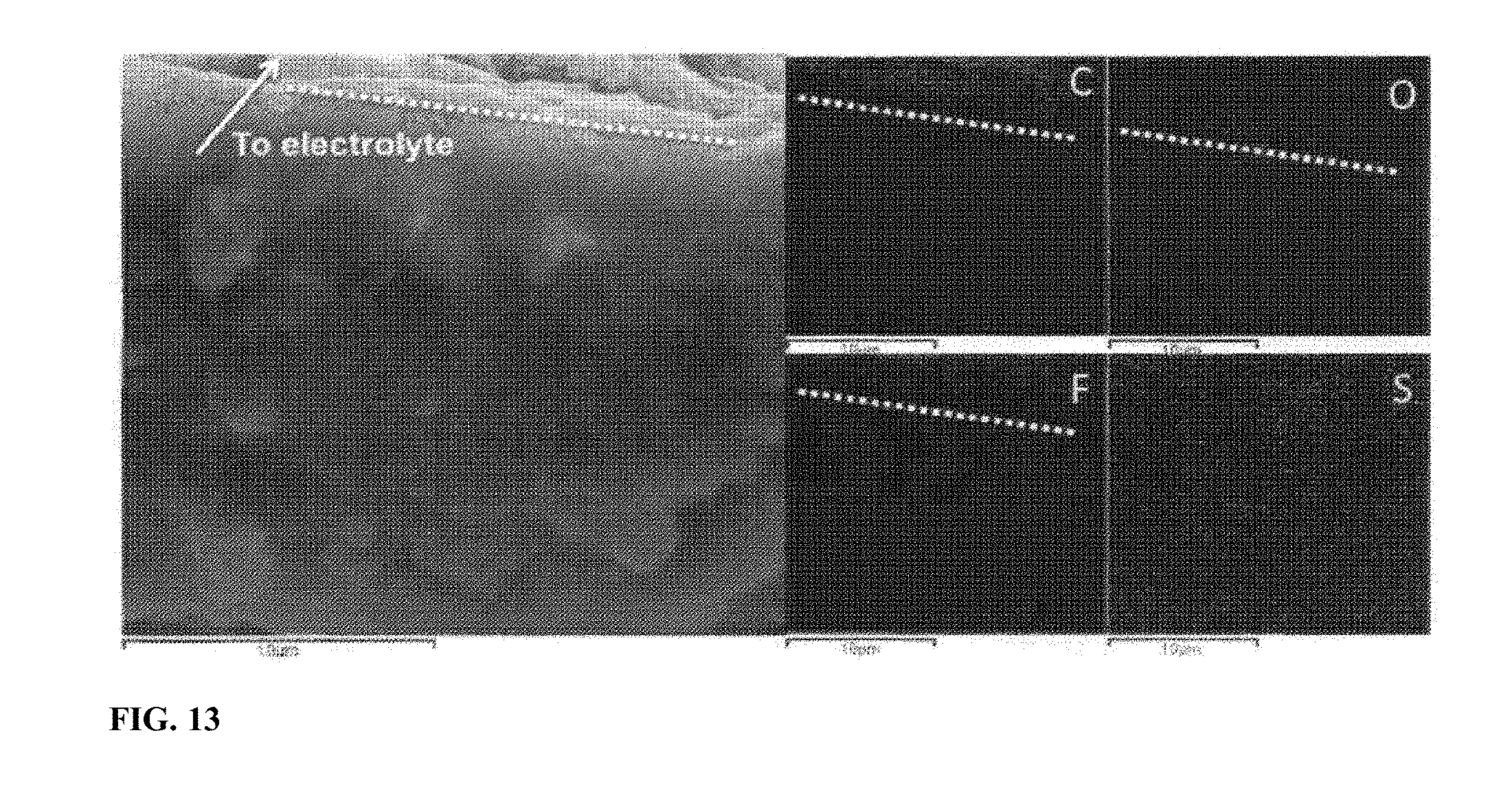
[0020] FIG. 13 SEM image and the corresponding EDS element map of the cross-section of the electrode made of SULFUN after charging/discharging two cycles (different sample with FIG. 5b). The dashed white shows the boundary between the newly formed carbon layer and the electrode film.
[0021] FIG. 14 shows a schematic illustration of reaction mechanism during charging and discharging. (a) illustrates that a sulfur particle generates holes and cracks due to the anisotropic reaction. Commercial sulfur particle shows a much larger Scontact/Vs ratio (b) compared to the compact SULFUN matrix (c), which greatly delays the loss of sulfur during electrochemical reaction.
[0022] FIG. 15 Illustration of the reaction mechanism during the charging and discharging. a) The commercial sulfur particle exhibits more pathways of lithium polysulfide/electrolyte contact, while b), the generated carbon-rich layer reduces the solid (matrix)/liquid (electrolyte) interface thus prevents the major loss of active material sulfur.
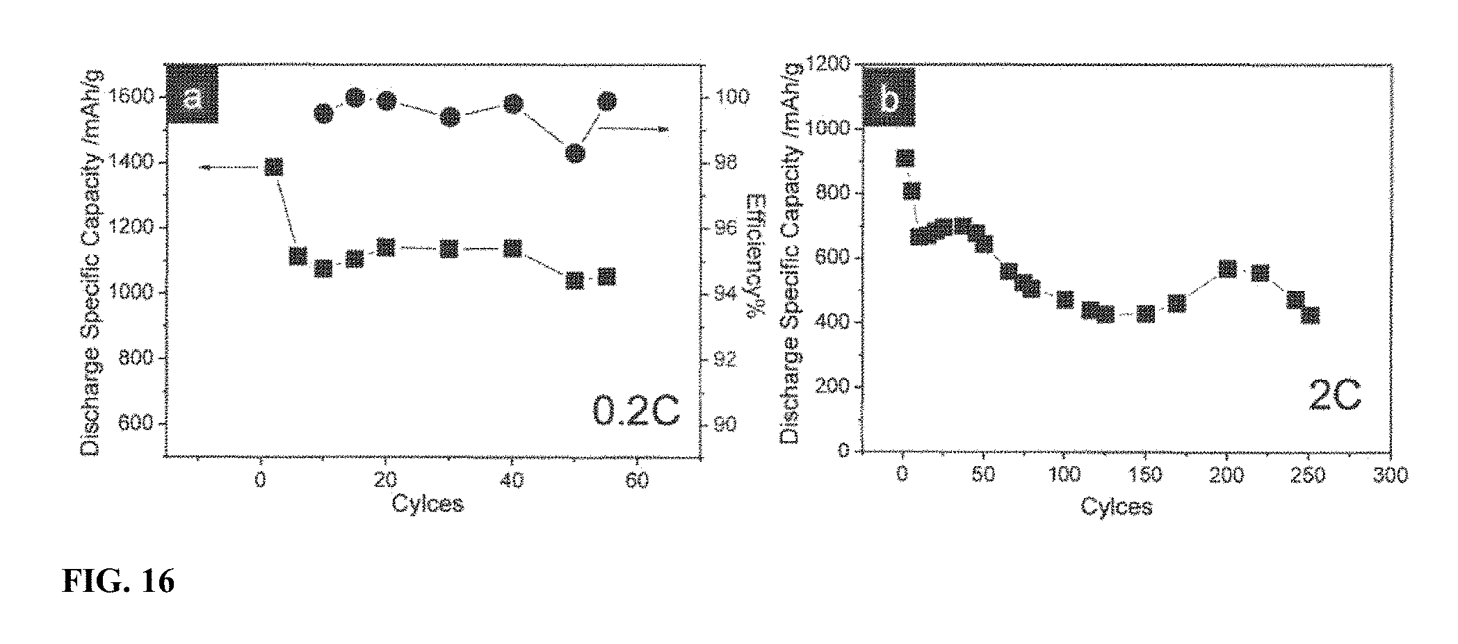
[0023] FIG. 16 shows electrochemical cycling performance of modified SULFUN coin-cell batteries at (a) C-rate of 0.2 and (b) C-rate of 2.0. (a) also shows Coulombic efficiency at 0.2 C-rate.
[0024] FIG. 17 shows XRD patterns of raw sulfur, annealed sulfur-carbon matrices, and the SULFUN matrix after 7 charge/discharge cycles ending in charging.
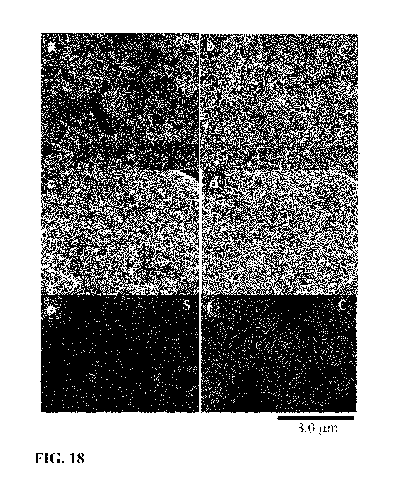
[0025] FIG. 18 SEM images and energy-dispersive X-ray spectroscopy (EDS) maps of the sulfur-carbon matrix. (a) SEM morphology of the sulfur-carbon matrix before annealing at 200.degree. C. for 2.5 hours. (b) Sulfur and carbon EDS map of area shown in (a). (c) SEM morphology of the sulfur-carbon matrix after annealing at 200.degree. C. for 2.5 hours. (d)-(f) Sulfur and carbon EDS map of area shown in (c).
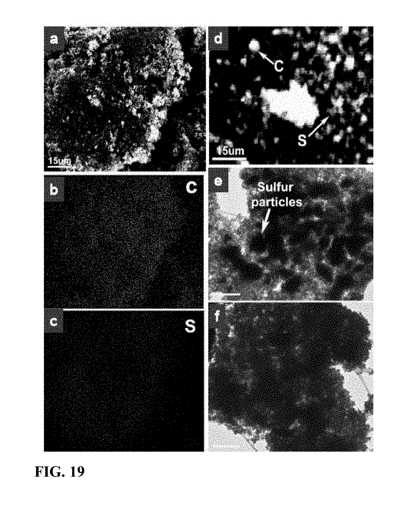
[0026] FIG. 19 EDS maps and TEM images of the sulfur-carbon matrix. (a) SEM morphology of the matrix annealed at 150.degree. C. for 50 hours. (b) carbon map of the area shown in (a). (c) sulfur map of the area shown in (a). (d) sulfur and carbon map of as-receive sulfur-carbon matrix before heating. (e) TEM image of the sulfur-carbon matrix before heating at 200.degree. C. for 2.5 hours. (f) TEM image of the sulfur-carbon matrix after heating at 200.degree. C. for 2.5 hours. Scale bar in (e) and (f) is 5 .mu.m.
DETAILED DESCRIPTION
[0027] The description provided herein describes a method of production with novel processing steps described in detail, as well as novel sulfur containing cathodes, and Li batteries comprising such cathodes. The various embodiments provide a cheap and simple approach to manufacture sulfur-based electrodes with carbon additives for high-capacity lithium ion batteries with long cycle life. All documents disclosed herein are incorporated by reference in their entirety for all purposes.
[0028] In various embodiments, the present invention comprises liquid-based, low-cost and reliable synthetic methods for lithium-sulfur composite cathodes containing an open network of conductive carbon black nanoparticles (Cnet), infused with sulfur (Snet) to form sponge-like networks (Cnet+Snet). Without limitation to a specific mechanism, it is believed that Snet has open access to the outside, allowing liquid electrolyte to infiltrate and impart Snet Li.sup.+ conductivity. During lithiation, Cnet accommodates the volume expansion of Snet without substantially losing electrical contact due to the interconnected nature of the network. During delithiation, the carbon nanoparticles flocculate on the outer surface of the composite due to depletion of sulfur by polysulfide dissolution, to form a passivation layer that still allows Li.sup.+ exchange, but preferentially slows down the loss of sulfur into the bulk electrolyte liquid. By using an extra carbon deposition layer to provide a carbonaceous passivation layer, improved performance is provided, i.e., about 400 mAh/g of discharge specific capacity after 250 cycles under a high C-rate 2.0. A 763 mAh/g discharge specific capacity for this sulfur nanosponge cathode (abbreviated as "SULFUN") was obtained after 100 cycles under a C-rate of 0.2. 520 mAh/g and 290 mAh/g discharge capacities were attained after 300 and 500 cycles, respectively.
[0029] As described in some embodiments, commercially available Conductive Carbon Blacks (such as Super P.RTM.) are used in a facile wet-chemistry method to synthesize a sulfur-carbon nanosponge. One of the purposes is to enhance cyclability by using the evolving microstructure of sulfur-carbon nanosponge during lithiation and delithiation process to help delay the loss of active sulfur ions. This approach utilizes cheap carbon black as the base matrix to construct a sulfur-covering-carbon sponge, instead of utilizing the traditional carbon-wrapping-sulfur geometry. Even though sulfur is not coated over the carbon in the beginning prior to first lithiation, the nanosponge structure of the composite synthesized using the described method can reduce sulfur loss during cycling.
[0030] To construct a well-blended matrix, a three-step process was developed: 1) Conductive Carbon Blacks such as Super P.RTM. were first functionalized by an acid such as hydrochloric acid, as shown in FIG. 1a. The carbon nanoparticles of .about.70 nm in diameter adhere to each other, forming a percolating electrical network (Cnet, FIG. 1a); 2) The in-situ formed small sulfur particles surrounded with surfactants were dispersed in the solution with Super P using a redox reaction (e.g., disproportionation of thiosulfate under acidic conditions) under agitation, such as ultrasonic or mechanical agitation (FIG. 1b-c); The ultrasonic agitation breaks apart carbon particle agglomerations, enabling in-situ formation of small sulfur-carbon clusters (2-4 .mu.m), as shown in FIG. 6c-d. For comparison, a well-mixed S/C composite prepared via mortar milling without sonication displays separate, flat sulfur flakes with much larger sizes of 40-60 .mu.m (FIG. 6b). 3) With heating at an annealing temperature of 150.degree. C. or 200.degree. C., the distributed sulfur was melted and deeply infiltrated into the framework and spread across the carbon surface, to form a sulfur-covering-carbon configuration, which is the other percolating network (Snet) (FIGS. 1d and 6e-f). Cnet and Snet interpenetrate each other and are in intimate contact, forming a nanostructured sponge which we call SULFUN. During lithiation/delithiation, the sponge-like structure of Cnet has the ability to "breath" to accommodate .about.80% volume expansion of Snet without losing electrical contact, according to the porosity calculation SULFUN has a different initial topology (Cnet+Snet, with both initially open to the outside) from the known carbon-wrapping-sulfur approach where the intent is to completely encapsulate and isolate the sulfur.
In-Situ Synthesis of Sulfur-Carbon Sponge Matrix
[0031] Details of the in-situ synthesis of Sulfur-Carbon sponge matrix are as follows. In one embodiment 70 wt % (according to the approximate loading in the final S--C matrix) Conductive Carbon Blacks (Super C65, Timical) was first treated in a solution mixed with 20 ml hydrochloric acid (1 N volumetric solution, Avantor Performance Materials, Inc.) under stirring on a hot plate (Super-Nuova, Thermo Scientific) for 2 hours at 70.degree. C. Then 100 ml deionized water was added. Meanwhile, sodium thiosulfate (anhydrous, 99%, Alfa Aesar) was dissolved in 150 ml deionized water with surfactant Triton X-100 (1% in deionized water, Alfa Aesar).sup.17. Then, the sodium thiosulfate solution was added into the Conductive Carbon Blacks solution with a dropping speed of .about.1 mL/min under an ultrasonic agitation (Symphony, VWR Ultrasonic Cleaner) at a constant temperature of 70.degree. C. The reacted sample was centrifuged (IEC HN-SII Centrifuge, Damon/IEC Division) and dried at 60.degree. C. in an oven (Symphony, VWR). Finally, the dried mixture was annealed at temperatures of 150.degree. C. for 50 hours ("low-temperature") or 200.degree. C. for 2.5 hours ("high-temperature") in air, respectively. The collected samples were stored for coin cell assembly and battery performance test.
[0032] It will be recognized by the skilled artisan that a variety of commercially available conductive carbon blacks, in suitable amounts, can be employed, such as Akzo Nobel's Ketjenblack family of carbon blacks or Cabot Corporation's LITX.TM. family of carbon blacks. In addition, other mineral acids such as sulfuric, nitric, etc. could be employed.
[0033] For comparison, 80 wt % commercial sulfur (Sulfur powder, 99.5%, Alfa Aesar), 10 wt % Super P and 10 wt % binder were uniformly milled for 30 minutes in a mortar. After the milling, the mixture was applied to make a slurry on Al foil and then the final coin cell was assembled using a same protocol.
Characterizations of Morphology, Chemical Composition, and Structure
[0034] SEM: The surface morphologies were evaluated using a FEI/Philips XL30 FEG Environmental Scanning Electron Microscope (ESEM) and JEOL 6320 Field-Emission High-Resolution SEM at 5-10 kV incident energy. The carbon-sulfur elemental mapping was obtained through energy-dispersive spectroscopy microanalysis using an INCA EDS detector at 20 kV acceleration voltage.
[0035] TEM: The in-situ formed sulfur and S--C sponge treated at different annealing temperatures were characterized by transmission electron microscopy (TEM) using a JEOL JEM-2010F at an accelerating voltage of 200 kV. The TEM sample was dispersed on a lacy carbon film supported on a copper grid to acquire the images. In order to reduce electron-beam damage, a low magnification with weak beam intensity was applied when the images were captured.
[0036] TGA: Thermal gravimetric analysis (TGA, SEIKO SSC/5200 TG/DTA220 thermal analysis station) and differential scanning calorimetry curves were recorded in argon as working gas. The temperature program was set to be isothermal at 50.degree. C. for 10 min and heated up to 650.degree. C. with a heating rate of 10.degree. C. min'.
[0037] Battery performance of SULFUN was measured via coin cells, which were assembled inside a glove box. SULFUN was used as the cathode while a Li foil served as the anode, in an electrolyte of 1.0 M lithium bis-trifluoromethanesulfonylimide (LiTFSI) in 1,3-dioxolane (DOL) and 1,2-dimethoxyethane (DME) (DOL:DME=1:1 in volume). Because the Snet is initially open to the outside, the LiTFSI+DOL+DME liquid electrolyte wets and infiltrates Snet in the initial lithiation, dissolving some sulfur and forming some soluble lithium polysulfides. The "wet" Snet then has some significant Li.sup.+ conductivity that percolates within Cnet.
[0038] FIG. 2a depicts an initial discharge specific capacity of .about.1100 mAh/g at a 0.2 C rate (C rate is calculated based on the theoretical capacity 1675 mAh/g of sulfur). Two main plateaus appear in the discharging window of 2.5 to 1.5 V (FIG. 2a). The first plateau (I) centering at .about.2.3 V corresponds to the sequential reduction of sulfur (S.sub.8) to high-order polysulfides Li.sub.2S.sub.X (4.ltoreq.X.ltoreq.8). During the complex reactions, a series of soluble lithium polysulfides are generated. As illustrated in the discharge curve, this plateau is quite short, which only presents a minor capacity of .about.165 mAh/g (about 15% of the overall 1100 mAh/g). Then there is a short transition (II), which contributes a small portion .about.146 mAh/g (.about.13%) as well. A big plateau (III) is located at .about.2.06 V, which is attributed to the continuous conversion of Li.sub.2S.sub.X (4.ltoreq.X.ltoreq.8) to low order Li.sub.2S.sub.2 and Li.sub.2S. In this last step, sulfur is reduced to the final state of insoluble Li.sub.2S, as described by C. Barchasz, F. Molton, C. Duboc, J. C. Lepretre, S. Patoux and F. Alloin in Analytical Chemistry, 2012, 84, 3973-3980. The dominance of this reaction is evidenced by the long plateau which constitutes a major portion (.about.64%) of the total capacity. Although the insoluble sulfides can increase the volume and the electrical resistance, plenty of interlinked carbon nanoparticles maintain good electron conduction paths to ensure uninterrupted lithiation/delithiation. In other words, Cnet is mechanically robust enough and has nano-pore-like configuration (Specific surface area: >70 m.sup.2/g) with flexibility that it can accommodate the .about.80% volume change of Snet by unfolding, while maintaining good electrical conductivity and contact with Snet. Otherwise the cycling performance would degrade very rapidly, which was indeed the case historically.
[0039] Shown in FIG. 2b is the cycling capability of SULFUN cathode annealed at 200.degree. C. With a charging/discharging rate of 0.2 C, a specific discharge capacity as high as .about.763 mAh/g was retained after running 100 cycles. After 300 cycles, a .about.520 mAh/g capacity was still retained, which implies less than 0.2% decay for each cycle (FIG. 2b). The capacity was maintained at a high level of .about.290 mAh/g even at the 500.sup.th cycle. A long-cyclability coin cell made of the same matrix is shown in FIG. 3, demonstrating reproducibility. Because of the multi-step procedure during material synthesis and battery assembly, a minor variation in performance inevitably exists. The 150.degree. C. annealed sample displays a better cycling behavior, as evidenced in FIG. 2c. After being subjected to extremely long cycling such as 1500 cycles, the discharge capacity is still as high as 158 mAh/g (FIG. 2c). It is noted that after running 1100 cycles, the capacity shows almost no significant drop (FIG. 2c inset). A comparison of battery performance using the disclosed methods and compositions with the literature is shown in Table 1.
TABLE-US-00001 TABLE 1 The battery performance of different Li--S battery systems. 1.sup.st Reversible Discharge Discharge Charge Degradation Capacity Capacity Rate Total Cycle Rate Per Sulfur Approach (mAh/g) (mAh/g) (mA/g) Number Cycle Loading Ref. SULFUN 1000-1400 520 (300.sup.th, 335 >500 0.24% (0.2 C) 65 wt % Current 0.2 C) (0.2 C) 0.36% (2 C) (2 mg/cm.sup.2) work 290 (500.sup.th, 3350 (2 C) 0.2 C) 400 (250.sup.th, 2 C) S--TiO.sub.2 yolk-shell 1,030 690 836 (C/2) 1,000 0.033% 53 wt %, 1 nanocomposite 0.4-0.6 mg/cm.sup.2 Solvent-in-salt electrolyte 1,041 770 335 (C/5) 100 0.26% 48 wt % 2 Ordered mesoporous C--S 1,070 700 1675 (1C) 100 0.35% 57 wt % 3 Double-shelled C--S 1,020 690 167 (C/10) 100 0.32% 45 wt % 4 composite Porous hollow C--S 1,071 974 836 (C/2) 100 0.09% 65 wt % 5 composite Hollow CNF-encapsulated S ~1,400 730 836 (C/2) 150 0.48% ~1.0 mg/cm.sup.2 6 Amphiphilic surface- 828 ~660 836 (C/2) 300 0.07% ~1.0 mg/cm.sup.2 7 modified hollow CNF-S Ultrasound-assisted S--C 1,195 836 230 100 0.30% 29 wt % 8 with fluorinated ether S molecules in a C/CNT 1,670 1,142 167.5 (C/10) 200 0.16% 32 wt % 9 matrix Li--S with interlayers with 1,483 600 and 1000 335 (C/5) >300 0.0011% 70 wt % 10 modified recharge setting (600 mAh/g) (600 mAh/g) >200 0.0027% (1000 mAh/g) (1000 mAh/g) 1. Z. W. Seh, W. Li, J. J. Cha, G. Zheng, Y. Yang, M. T. McDowell, P.-C. Hsu and Y. Cui, in Nature Communications, 2013, 4, 6 2. L. M. Suo, Y. S. Hu, H. Li, M. Armand and L. Q. Chen, in Nature Communications, 2013, 4 3. J. Schuster, G. He, B Mandlemeier, T. Yim, K. T. Lee, T. Bein and L. F. Nazar, Angew. Chem.-Int. Edit., 2012, 51, 3591-3595. 4. C. F. Zhang, H. B. Wu, C. Z. Yuan, Z. P. Guo and X. W. Lou, Angew. Chem.-Int. Edit., 2012, 51, 9592-9595. 5. N. Jayaprakash, J. Shen, S. S. Moganty, A. Corona and L. A. Archer, in Angewandte Chemie International Edition, 2011, 50, 5904-5908. 6. G. Y. Zheng, Y. Yang, J. J. Cha, S. S. Hong and Y. Cui, in Nano Letters, 2011, 11, 4462-4467. 7. G. Y. Zheng, Q. F. Zhang, J. J. Cha, Y. Yang, W. Y. Li, Z. W. She and Y. Cui, Nano Lett, 2013, 13, 1265-1270. 8. W. Weng, V. G. Pol, and K. Amine, Adv Mater, 2013, 25, 1608-1615. 9. A. Manthiram, Y. Z. Fu and Y. S. Su, Accounts Chem. Res., 2013, 46, 1125-1134 10. Y. S. Su, Y. Z. Fu, T. Cochell and A. Manthiram, in Nature Communications, 2013, 4, 2985.
[0040] For microstructural comparison, coin cells made of commercial pure sulfur and mortar-milled S/C mixture cathodes were also tested, as shown in FIGS. 2b and 3. For the pure sulfur, the capacity drastically decreased from .about.856 mAh/g to less than 200 mAh/g after only 15 cycles. The battery almost died after 29 cycles. As for the mortar-milled S/C mixture, the capacity dropped to less than 300 mAh/g after 100 cycles and almost down to zero at the 200.sup.th cycle (FIG. 2b). The two plateaus from the charge/discharge voltage profile almost disappeared after 200 cycles (FIG. 4) while they were still observed apparently even after 1500 cycles in SULFUN (FIG. 5). It was further observed that in the coin cell assembly with the SULFUN cathode, adding a trace of conductive polymer polypyrrole (PPy) in the SULFUN/binder/Super P slurry acts as a network to restrain the dissolution of intermediate products. It will not impair Li.sup.+/e.sup.- transport due to the relatively high electric conductivity (0.005 Scm.sup.-1) of PPy, and appears to trap both polysulfides and possibly detached sulfur particles without raising resistance, which can further reduces the rate at which the capacity of the cell decreases.
[0041] The atomic structure and evolution of sulfur inside SULFUN was investigated. As shown in FIG. 17, the X-ray diffraction pattern (XRD) of the as-received raw sulfur indicates an orthorhombic structure. After annealing, a monoclinic crystalline structure was stabilized. A totally amorphous structure of sulfur was found upon the completion of 7 cycles (ending in charging) of the SULFUN cathode.
[0042] The morphology of sulfur was characterized by electron microscopy. As shown in FIG. 7a, the as-fabricated sulfur without carbon host has a particle size ranging 5-10 .mu.m. The commercial sulfur after mortar milling has a particle size ranging 40-60 .mu.m (FIG. 6a-b). However, during SULFUN fabrication step 2), the size of sulfur particles dispersed on the carbon matrix surface becomes smaller (FIGS. 6c-d and 8d-e/19d-e), corresponding to sulfur particle sizes of 2-4 .mu.m, which is about 50% less than the particles size of free-standing sulfur in FIG. 7a and much smaller than the commercial pure (FIG. 10a) and mortar-milled (FIG. 6a-b) sulfur. The sulfur was dispersed rather uniformly on the carbon surface, as illustrated from the energy-dispersive X-ray spectroscopy (EDS) mapping in FIGS. 6d and 8d/19d. In contrast to the separate sulfur particles after milling (FIG. 6a-b), the ball-like S/C cluster with decreased sizes ensures a sufficient contact, leading to a high ion/electron conductivity (FIG. 6c-d). In order to further reduce the microstructural length scale and form a compact nanoscale S--C network, the sulfur was subsequently melted during SULFUN fabrication step 3 at 150.degree. C. or 200.degree. C. Under this temperature, like a water filtering sponge, the fluidic sulfur permeated inside the carbon sponge (FIG. 1d). As displayed in FIGS. 6e-f and FIGS. 7b-c, after heating the sulfur almost cannot be isolated from the Cnet any more. TEM images of the 200.degree. C. treated sample also exhibits a uniform composition (FIGS. 8f and 19f). Elemental mapping of local areas clearly shows a proportional distribution of sulfur and carbon (FIGS. 3d-f and 7a-c/19a-c). These data imply that Snet has been interfused with the nanostructured Cnet, with improved adhesion between sulfur and carbon, providing a fast pathway for ion/electron transport. According to the estimated volume of the matrix, the gravimetric loading of sulfur is about 70 wt %. Quantitative thermal-gravimetric analysis (TGA) reveals the final loading of sulfur in SULFUN was 62 and 65 wt % after heat treatment at 150 and 200.degree. C., respectively. (FIG. 9).
[0043] The initial size of sulfur particles plays a critical role on the imbibition process and the later cyclability of the resulting electrochemical cell. To obtain a homogenous cathode, well-dispersed sulfur particles with a small size are significant. In the present method, carbon black first underwent acid treatment in hydrochloric acid to create functional hydroxyl/carboxyl groups. In parallel, the added surfactant groups surrounded the fresh sulfur particles to prevent Ostwald ripening. The surfactant also helped to disperse the sulfur particles more efficiently in the matrix. Then, a very important step is the slow redox reaction, in which e.g. sodium thiosulfate solution was added into the functionalized carbon suspension slowly, drop by drop, with vigorous agitation. As a result, sulfur with a reduced particle size uniformly spread over a wide area of the carbon surface was provided, and which was subsequently melted and spread further by annealing at 150.degree. C. for 50 hours or at 200.degree. C. for 2.5 hours (FIG. 6c-d). In contrast, the particle size of commercial ground and pure sulfur possesses is 40-60 .mu.m (FIGS. 6a-b and 10a-b).
[0044] Next, we investigated the morphological evolution of the electrode surface during lithiation/delithiation. As can be seen from FIG. 10a, the surface of the original commercial sulfur is quite smooth. A clear boundary between sulfur and other materials like carbon and binder is observed via elemental mapping (FIG. 10b). However after only two cycles, several holes with size 2-4 .mu.m were observed in the sulfur particles, which by then were already severely deformed and shrunk, indicating a fast loss of the active sulfur (FIG. 10c-d and FIG. 11). The sulfur particles were dramatically deformed and broke into small particles which were dispersed among the surface inhomogeneously (FIG. 11). In contrast, the surface of the SULFUN electrode is still smooth after the cycling, as shown in FIG. 10e. The elemental sulfur map indicates a homogeneous distribution (FIG. 100. From analysis of the cross-section of the pure sulfur electrode, 0 and F which can only be precipitated out from the electrolyte was found to be dispersed across the whole electrode film (.about.40 .mu.m, FIG. 12a), indicating deep invasion of the liquid electrolyte and corrosion of the sulfur. However, the 0 and F elements were highly concentrated at the top surface (1-2 .mu.m) with the SULFUN electrode (FIGS. 12b and 13), indicating liquid electrolyte invasion and corrosion were probably repelled from the inside matrix. The corrosion reaction is believed to be heterogeneous and anisotropic, as illustrated in FIGS. 14a and 15a. Some locations will be more heavily corroded and consequently generate holes/cracks, causing the whole particle to split (FIG. 14a). The electrode surface composed of pure or milled sulfur displays a larger solid-liquid interface Scontact to the liquid electrolyte but with a smaller volume of sulfur Vs (FIG. 14b and FIG. 15a). In this case, the liquid electrolyte can easily permeate into the electrode (FIG. 12a), which also creates a path to carry away the soluble polysulfides. However, the compactly nanostructured SULFUN exposes only a very small area of naked sulfur to the liquid electrolyte (FIGS. 14c and 15b) limiting the sulfur dissolution, even when the intermediate lithium polysulfides are formed inside. Here a possible mechanism is suggested. Because the Snet is initially open to the outside, the LiTFSI+DOL+DME liquid electrolyte wets and infiltrates Snet in the initial lithiation, dissolving some sulfur and forming some soluble lithium polysulfides. The "wet" Snet then has some significant Li.sup.+ conductivity that percolates within Cnet. However, once the embedded sulfur on the top is dispersed, the carbon nanoparticles remaining (tens to hundreds nanometers, as shown in FIGS. 12b and 13) concentrates to form a dense carbon-rich layer as a passivation layer against corrosion, which serves like a sieve to selectively block larger molecules such as the electrolyte and polysulfide while allowing small charged species (L.sup.+/e.sup.-) to pass through (FIGS. 14c and 15).
[0045] An additional carbon layer with tens of microns thickness was coated on the SULFUN surface. FIG. 16 shows the cycling performance and coulombic efficiency of the modified SULFUN battery at different charge/discharge rates. As can be seen from FIG. 16a, an initial >1300 mAh/g capacity was achieved and then was maintained at a value of .about.1100 mAh/g until 60 cycles, accompanying with the coulombic efficiency >98%. Under the 10 times faster charging/discharging (2.0 C), a special discharge capacity of .about.400 mAh/g was still attained after 250 cycles (FIG. 16b). This high rate capability indicates the extra carbon can act as a passivation layer to reduce the "shuttling effect", as the in-situ formed carbon-rich passivation layer on SULFUN surface, leading to a long battery life.
[0046] To better understand the microstructure of the samples, FIG. 17 shows XRD patterns of raw sulfur, annealed sulfur-carbon matrices, and the SULFUN matrix after 7 charge/discharge cycles ending in charging. In addition, FIG. 18 shows SEM images and energy-dispersive X-ray spectroscopy (EDS) maps of the sulfur-carbon matrix: (a) SEM morphology of the sulfur-carbon matrix before annealing at 200.degree. C. for 2.5 hours. (b) Sulfur and carbon EDS map of area shown in (a). (c) SEM morphology of the sulfur-carbon matrix after annealing at 200.degree. C. for 2.5 hours. (d)-(f) Sulfur and carbon EDS map of area shown in (c).
[0047] Additional micrographs are shown in FIG. 19, which includes EDS maps and TEM images of the sulfur-carbon matrix: (a) SEM morphology of the matrix annealed at 150.degree. C. for 50 hours. (b) carbon map of the area shown in (a). (c) sulfur map of the area shown in (a). (d) sulfur and carbon map of as-receive sulfur-carbon matrix before heating. (e) TEM image of the sulfur-carbon matrix before heating at 200.degree. C. for 2.5 hours. (f) TEM image of the sulfur-carbon matrix after heating at 200.degree. C. for 2.5 hours. Scsle bar in (e) and (f) is 5 .mu.m.
[0048] To better understand the selective permeation effect, the size dependence of the molecule/ion on the solubility and diffusion coefficient inside the Super-P can be calculated. The mass transport flux is proportional to the product of the solubility and the diffusion coefficient in carbon black, as
J .about. k B T 6 .pi. M 1 / 2 a exp ( - Q k B T ) , ( 1 ) ##EQU00001##
[0049] where k.sub.B is the Boltzmann constant, T is temperature, M and a are the mass and the average radius of the molecule/particle, respectively. Q is the effective activation energy, combining both insertion energy and migration energy barrier. When a molecule/ion in the liquid electrolyte is inserted into and diffuses inside the passivation layer, both interfacial and elastic energies contribute to Q:
Q .apprxeq. F surface + F elastic = 4 .pi. a 2 .gamma. + 24 .pi. a 3 .mu. K 2 3 K + 4 .mu. , ( 2 ) ##EQU00002##
[0050] where .gamma. is the interfacial energy, K, .mu. and .epsilon. are the bulk modulus, shear modulus and dilatational misfit strain, respectively. For small particles such as single lithium ion, molecular sulfur/polysulfide ion, or even electrolyte, F.sub.surface>>F.sub.elastic, and eq. (2) becomes Q.apprxeq.S.gamma.. Here, S is the surface area. The average surface energy of SuperP is .about.100 mJ/m.sup.2 and the surface area of Li ion, small sulfur molecules S.sub.4 and S.sub.8 can be estimated using lithium ion radius of 1.34 .ANG. and the bond length values of various small sulfur molecules. Thus, from eq. (1) and (2) the ratio of permeation fluxes J(X) (X=Li, S.sub.4, S.sub.8) as J(Li): J(S.sub.4): J(S.sub.8)=1:10.sup.-3:10.sup.-8 is obtained, showing the permeation of the S.sub.8 cluster is eight orders of magnitude slower than Li. The upshot of the above rough estimation is that a pure carbon layer (blocking the invasion of the liquid electrolyte into Snet) can selectively allow L.sup.+/e.sup.- to easily get in, but prevent the larger polysulfides Li.sub.2S.sub.X (4.ltoreq.X.ltoreq.8) from getting in or out, thus slowing down the shuttling effect and act as a passivating molecular sieve. Also, the fine-meshed Cnet will probably restrain and block much smaller sulfur particles from breaking off Snet mechanically and convecting into the liquid, even with a certain degree of heterogeneous corrosion. In other words, the SULFUN nanocomposite can better facilitate stress relaxation and enhance flaw tolerance, which may be a generic behavior of nano-scale electrode materials.
[0051] In conclusion, the in-situ synthesized sulfur-carbon nanosponge using Conductive Carbon Blacks as a host greatly slowed down the loss of sulfur, hereby displaying a better cycling performance while maintaining a high capacity. The suggested passivation layer or extra carbon layers can prevent the decay of capacity by limiting the transport of the larger polysulfides Li.sub.2S.sub.X (4.ltoreq.X.ltoreq.8) without slowing down L.sup.+/e.sup.-. This "defense-in-depth" strategy is distinct from the complete encapsulation or the "defense-in-perimeter" strategy most researchers have employed. The improved coin-cell scale performance discussed herein indicates that the polysulfides shuttling effect is ameliorable through nanostructural design and engineering. The high capacity, long cyclability, cheap raw materials and simple preparation make the SULFUN cathode material suitable for industrial scale production.
Characterization of Battery Performance
[0052] Battery behavior of the synthesized material was performed via a coin cell. Typically, a CR2032 coin cell (MTI) with a lithium foil as counter/reference electrode was assembled in an argon-filled glove box (LABmaster SP, MBraun) with both O.sub.2 and H.sub.2O concentrations lower than 0.1 ppm. Celgard 2400 was used as the separator. For liquid electrolyte, 1.0 M lithium bis-trifluoromethanesulfonylimide in 1,3-dioxolane and 1,2-dimethoxyethane (volume ratio 1:1, Novolyte) was employed, although the skilled artisan will recognize that other electrolytes such as those containing lithium salts (e.g., LiPF.sub.6, LiBF.sub.4 or LiClO.sub.4) and combination of linear and cyclic carbonates (e.g., ethylene carbonate, dimethyl carbonate or poly(oxyethylene)) can also suitably be employed. Certain relevant battery performance characteristics were tested without additives except the rate data shown in FIG. 7. A hydraulic crimping machine (MSK-110, MTI) was employed to close the cell. To make a slurry, the active material of sulfur-Super P sponge, or pure sulfur synthesized using a same method but without carbon, or milled sulfur/carbon mixture was blended with 10 wt % Super C65 (Timical), 10 wt % poly (vinylidene fluoride) binder (MTI), and a small amount of polypyrrole solution (polypyrrole doped, 5 wt % dispersion in H.sub.2O, conductivity of dried cast film: >0.0005 S/cm, Sigma-Aldrich) dissolved in N-methylpyrrolidone (MTI). The sulfur loading was designed to be 1.0 mg/cm.sup.2 for 150.degree. C. sample and 2.0 mg/cm.sup.2 for 200.degree. C. sample, respectively. The mixture was sonicated until a homogeneous slurry was formed. Then the slurry was coated onto an aluminum foil current collector. After drying 2 hours at 90.degree. C. in an oven, the sample was cut out to serve as a cathode.
[0053] For the high-rate charge/discharge test, an additional layer which is composed of carbon/binder was coated on the top of the dried slurry made of SULFUN. In a typical experiment, the melted sulfur/carbon mixture with 10 wt % SuperP and 10 wt % poly (vinylidene fluoride) binder was first coated on the aluminum foil, as described above. After the first slurry was almost dried, the secondary slurry composed of SuperP (80 wt %) and binder (20 wt %) with a loading of .about.2.0 mg/cm.sup.2 was coated on the surface. Then the sample was dried overnight at 65.degree. C. in an oven for battery assembling.
[0054] The packed coin cell was galvanostatically charged/discharged in a fixed voltage window between 1.4 and 2.5/2.8 V on a 12-channel Arbin Instruments BT2000 battery tester at room temperature. The cycling capability was recorded at a charging/discharging rate of 0.2 C and 2.0 C, respectively. The specific capacities were calculated based on the sulfur loading corrected by the TGA test.
* * * * *
D00001
D00002
D00003
D00004
D00005
D00006
D00007
D00008
D00009
D00010
D00011
D00012
D00013
D00014

D00015

D00016
D00017

D00018
D00019


XML
uspto.report is an independent third-party trademark research tool that is not affiliated, endorsed, or sponsored by the United States Patent and Trademark Office (USPTO) or any other governmental organization. The information provided by uspto.report is based on publicly available data at the time of writing and is intended for informational purposes only.
While we strive to provide accurate and up-to-date information, we do not guarantee the accuracy, completeness, reliability, or suitability of the information displayed on this site. The use of this site is at your own risk. Any reliance you place on such information is therefore strictly at your own risk.
All official trademark data, including owner information, should be verified by visiting the official USPTO website at www.uspto.gov. This site is not intended to replace professional legal advice and should not be used as a substitute for consulting with a legal professional who is knowledgeable about trademark law.