Portable Refrigerator And Method Of Using
MIROS; Robert H.J. ; et al.
U.S. patent application number 15/573781 was filed with the patent office on 2019-01-03 for portable refrigerator and method of using. This patent application is currently assigned to 3rd Stone Design Inc.. The applicant listed for this patent is 3rd Stone Design Inc.. Invention is credited to James A. McCREA, Robert H.J. MIROS, Keith B. PAYEA.
| Application Number | 20190003757 15/573781 |
| Document ID | / |
| Family ID | 57248954 |
| Filed Date | 2019-01-03 |


View All Diagrams
| United States Patent Application | 20190003757 |
| Kind Code | A1 |
| MIROS; Robert H.J. ; et al. | January 3, 2019 |
PORTABLE REFRIGERATOR AND METHOD OF USING
Abstract
A portable refrigeration system for use in transport of medicines or other valuable, temperature sensitive materials is disclosed. The system can use GPS positioning technology to provide absolute global location along with internet connection through a cellular modem on board which allows for communication to the cloud of temperature and transit data during device use. The refrigerator can be powered by a rechargeable battery back that may be recharged through connection to AC mains supply or connection to the photovoltaic panel included with the device. The insulated container can be held at a constant temperature through the use of vacuum insulated panel construction. The device can be cooled through the use of thermoelectric cooling modules coupled to the insulated chamber and paired with a heat exchanger with heat pipes and a system fan. The device can be operated either through the included graphical user interface display via touch or buttons or it may be accessed and controlled by a remote computer through the cloud via a cellular connection.
| Inventors: | MIROS; Robert H.J.; (Fairfax, CA) ; PAYEA; Keith B.; (Santa Rosa, CA) ; McCREA; James A.; (San Carlos, CA) | ||||||||||
| Applicant: |
|
||||||||||
|---|---|---|---|---|---|---|---|---|---|---|---|
| Assignee: | 3rd Stone Design Inc. San Rafael CA |
||||||||||
| Family ID: | 57248954 | ||||||||||
| Appl. No.: | 15/573781 | ||||||||||
| Filed: | May 14, 2016 | ||||||||||
| PCT Filed: | May 14, 2016 | ||||||||||
| PCT NO: | PCT/IB16/00790 | ||||||||||
| 371 Date: | November 13, 2017 |
Related U.S. Patent Documents
| Application Number | Filing Date | Patent Number | ||
|---|---|---|---|---|
| 62161173 | May 13, 2015 | |||
| 62253272 | Nov 10, 2015 | |||
| Current U.S. Class: | 1/1 |
| Current CPC Class: | F25D 11/003 20130101; Y04S 10/50 20130101; H04L 67/12 20130101; G06Q 10/20 20130101; F25D 11/00 20130101; F25D 29/003 20130101; G01S 19/13 20130101; F25B 27/002 20130101; F25D 3/08 20130101; G06Q 10/0832 20130101; F25B 2321/0251 20130101; G06Q 50/28 20130101; F25D 2700/14 20130101; F25D 2700/12 20130101; F25B 21/02 20130101; F25D 2500/04 20130101 |
| International Class: | F25D 11/00 20060101 F25D011/00; F25D 29/00 20060101 F25D029/00; F25B 21/02 20060101 F25B021/02; G01S 19/13 20060101 G01S019/13; G06Q 10/00 20060101 G06Q010/00 |
Claims
1. A method for using a refrigeration unit system, wherein the system comprises: a portable refrigeration unit having an insulated internal space, wherein the unit is less than 22 kg, and wherein the portable refrigeration unit comprises batteries, a location sensor, a telecommunication radio, and one or more thermometers configured to measure an ambient temperature outside of the unit and an internal temperature inside of the internal space, and wherein the unit comprises a memory storing data regarding contents of the internal space; and a remote computer in data communication with the portable refrigeration unit, wherein the method comprises: calculating by the remote computer a remaining time of operable life of the refrigerator unit, wherein the operable life comprises the amount of time the unit has left wherein the internal space will remain above a desired temperature.
2. The method of claim 1, wherein the location sensor comprises a GPS receiver.
3. The method of claim 1, wherein the telecommunication radio comprises a cellular modem.
4. The method of claim 3, wherein the cellular modern comprises a GSM modem.
5. The method of claim 1 further comprising calculating by the remote computer a route (i.e., travel path) to a desired destination for the unit.
6. The method of claim 5 further comprising calculating the range of the unit, wherein the range is calculated with the remaining time of operable life, a length of the route, and a historical speed of the unit.
7. A refrigeration unit system comprising: an assembly having a cold chamber central to the assembly, the assembly comprising a thermoelectric module affixed to the chamber in direct contact, wherein the module is configured to allow for the immediate conduction of heat away from the cold chamber; insulation surrounding the cold chamber and arrayed in such a fashion so as to create a tight seal and well-insulated environment; a heat exchanger comprising fins; a heat conducting plate smaller than the heat exchanger, wherein the heat conducting plate comprising fins for conductive cooling by air circulation and heat pipes configured to conduct heat away from the plate to a larger heat exchanger, wherein the thermoelectric module is in mechanical contact with the heat conducting plate; a fan, wherein the heat exchanger is couple to the fan, and wherein the fan is configured to circulate cooling air over the fins of the heat exchanger to cool the system; thermal probes attached to the cold chamber, the heat exchanger, and exposed to ambient environment having an ambient temperature, wherein the probes are configured to monitor the system temperature states; a system microprocessor configured to monitor system temperature states and perform a cooling algorithm based on the system temperature states that maximizes cooling time for the cold chamber when powered by a rechargeable battery in the system housing.
8. The system of claim 7, wherein the cold chamber comprises a metal.
9. The system of claim 8, wherein the metal comprises aluminum sheet metal.
10. The system of claim 7, where the insulation is comprised of vacuum insulated panels.
11. The system of claim 8, wherein the insulation comprises vacuum insulated panels formed to the contours or the cold chamber and sealed at the edges with closed cell foam or polymer tape.
12. The system of claim 8, wherein the cooling algorithm is optimized to provide the greatest duration of cooling time when running on power coming from the rechargeable battery in the system.
13. The system of claim 12, wherein the algorithm allows the unit to run at a set temperature or a range of temperatures and pulse between on and off states so as to keep the average temperature within the range while using the least amount of power over time from the battery.
14. The system of claim 8 where the system microprocessor can sense the connection of the system to AC mains power and simultaneously seek to charge the battery while running the thermoelectric cooling module in order to cool the cold chamber.
15. The system of claim 14 where the thermoelectric cooling module is run at a heightened state of energy so as to rapidly cool the unit to the low end of the set temperature range.
16. The system of claim 14 where the algorithm controlling the thermoelectric module power state adjusts the power to the cooling module when the system is removed from AC Mains power and run solely on battery power in such a manner so as to conserve more power but still run within the specified temperature range over the longest possible hold time.
17. A method of cooling a refrigeration system wherein: a thermoelectric cooling module is pulsed with power from a power supply comprising a battery pack and/or AC mains power and, wherein if the power is AC, the power is then converted to DC delivered to the thermoelectric cooling module, and wherein the thermoelectric module is controlled by a microprocessor executing a software algorithm that monitors temperature provided by at least one temperature monitoring probe, wherein the software algorithm is configured to determine the optimum power to be delivered to the thermoelectric module at any given time in order to balance the requirements for rapid cooling of the cold chamber, preservation of the charge in the battery pack, and consistency of cold holding temperature in the cold chamber.
18. The method of claim 17, wherein the software algorithm adjusts the output of the power supply in response to the presence of external power provided by AC Mains connection, DC source connection from a PV solar panel or DC electric connection in a vehicle, or DC power coming from the battery pack in such a way so as to reduce battery depletion and keep the thermoelectric module running at an adequate rate to maintain set temperatures within the system.
19. The method of claim 17, wherein the software algorithm monitors the battery charge state and adjusts power to the thermoelectric module up and until the temperature readings from the system are outside of the temperature settings for the system and in turn the software signals to the system to sound any of a various range of alarms to notify the user of the device, or the remote monitor of the device performance, that the prescribed temperature range has been transgressed.
Description
CROSS-REFERENCE TO RELATED APPLICATION
[0001] The present application is related to U.S. Provisional Application No. 62/161,173, filed May 13, 2015, and 62/253,272, filed Nov. 10, 2015, both of which are incorporated by reference herein in their entireties.
BACKGROUND
1. Technical Field
[0002] A portable refrigerator, and more particularly to a portable, thermoelectric refrigerator with attendant temperature monitoring features useful in the transport of temperature sensitive materials is disclosed.
2. Description of the Related Art
[0003] Portable cooler boxes and refrigerators are available in various embodiments.
[0004] The need for controlled temperature delivery systems is present in many fields of use but none more obvious than in the transport of life saving vaccines to remote locations in the world. If the temperature of these vaccines goes too high or drops below freezing it can permanently inactivate the vaccines thus rendering them useless in inoculation against disease and can in some circumstances make them unsafe for use. Thus the need for refrigerating medicines is a serious problem in lesser developed countries and remote parts of the world without consistent electrical power.
[0005] In the delivery of life saving vaccines there is a need to monitor the temperature of vaccines as they are in transit. The World Health Organization stipulates that most vaccines are to be kept in a safe, cool range of 2 degrees to 8 degrees Celsius. The lack of constant, reliable monitoring systems for cooler boxes used in vaccine delivery programs creates uncertainty in the safety of medicines delivered, often times makes waste in that medicines that are unknown to have been kept within the safe range must be disposed of, and sometimes requires redundant and ineffective cooling methods to assure the safety range is maintained in absence of better methods to monitor the temperature of the contents of the delivery device. In light of this circumstance there is a need for constant monitoring of both internal temperatures close to the medicines or goods in transit and the ambient temperature the device is experiencing.
[0006] Because of the need to have medicines both readily available and maintained at a certain temperature, insulated containers have been available for many years for transporting vaccines and other similar medications in transit to the field site of use. However, most such devices are passive insulated containers filled with blocks of ice or frozen gel packs which rely on a separate freezer system for refreezing. There then remains a need for a self-contained, compact and portable cooling storage system for transporting items that require temperature control.
SUMMARY
[0007] A portable refrigerator that can be used as a medicine or temperature sensitive substances transport device that can maintain appropriate temperatures to prevent spoilage or damage to the items being transported is disclosed. The use of battery power to provide refrigeration in off-grid sites or when no AC mains power is available to power an electronic device is also disclosed. The battery in the refrigerator can be recharged through connection to AC mains power (e.g., a wall outlet connected to a generator or municipal grid power from a power plant), one or more photovoltaic panels on the refrigerator, or combinations thereof. The refrigerator can have highly efficient, vacuum insulated panel construction, for example, delivering a long lasting cold temperature retention vessel. Further, the refrigerator can have an onboard microcontroller and graphical user interface which allow for the management of and contact monitoring of both internal and external temperatures to the storage chamber, the ability to determine remaining battery charge, and both location through the use of a GPS module and communications to the internet cloud through a cellular modem connection.
[0008] Accordingly, described herein is a portable medical storage device, comprising an insulated container surrounded by vacuum insulated paneling; a thermoelectric cooler in thermal communication with the insulated container and cooled through contact with a heat exchanger and fan assembly; a battery energy source that is charged either through connection to AC mains or through the use of energy generated by the included photovoltaic module; a microcontroller on board control system with included GPS for location services and cellular connections for communication to internet cloud networks and simultaneous presentation of system performance.
[0009] Additionally, described herein is a portable medical storage device comprising an insulated container with an insulated door; an internal cavity surrounded by the insulated container; a cooling assembly in thermal communication with the cooling assembly comprising a cold plate, a thermal conduction member, a thermal electric cooler, a heat sink with heat pipe tubing, and a fan; a temperature sensor for sensing the temperature within the container; and a microcontroller and control input panel in electrical communication with the thermoelectric cooler, the temperature sensor and the battery.
[0010] Also disclosed is a refrigeration unit system that can have a portable refrigeration unit and a remote computer in data communication with the portable refrigerator unit. The refrigerator unit can have an insulated internal space. The unit can be less than 22 kg. The portable refrigeration unit can have batteries, a location sensor, a telecommunication radio, and one or more thermometers configured to measure the ambient temperature outside of the unit and the internal temperature inside of the internal space. The unit can have a memory storing data recording contents of the internal space.
[0011] The location sensor can have a GPS receiver. The telecommunication radio can have a cellular modem. The cellular modem can have a GSM modem.
[0012] A method for using the refrigeration unit system is disclosed. The method can include calculating by the remote computer a remaining time of operable life of the refrigerator unit. The operable life can include the amount of time the unit has left where the internal space will remain above a desired temperature. The method can also include calculating by the remote computer a route (i.e., travel path) to a desired destination for the unit.
[0013] The method can also include calculating the range of the unit. The range can be calculated with the remaining time of operable life, a length of the route, and a historical speed of the unit.
[0014] Further disclosed is a refrigeration unit system that can have a cold chamber central to an assembly with a thermoelectric module affixed to the chamber in direct contact whereby the contact can allow for the immediate conduction of heat away from the cold chamber. The system can have vacuum insulated panels surrounding the cold chamber and arrayed in such a fashion so as to create a tight seal and a well-insulated environment. The thermoelectric module can be in mechanical contact with a heat conducting plate that has both fins for conductive cooling by air circulation and heat pipes that conduct heat away from the plate and to a larger heat exchanger. The heat exchanger can be coupled to a fan that can circulate cooling air over the fins of the heat exchanger to cool the system. The system can have thermal probes attached to the cold chamber and the heat exchanger. The thermal probes can be exposed to ambient environment or temperature in a manner that allows for monitoring of the system temperatures or temperature states. These temperature states in turn can be monitored by the system microprocessor and used as inputs to a cooling algorithm that can provide the maximum amount of cooling time for the cold chamber when powered by a rechargeable battery in the system housing.
[0015] The cold chamber can be made from a metal, such as aluminum sheet metal. The vacuum insulated panels can be formed to the contours or the cold chamber and sealed at the edges with closed cell foam or polymer tape.
[0016] The algorithm used to run the thermoelectric cooling module can be optimized to provide the greatest duration of cooling time when running on power coming from the rechargeable battery in the system. The algorithm can allow the unit to run at a set temperature or a range of temperatures and pulse between on and off states so as to keep the average temperature within the desired range while using the least amount of power over time from the battery.
[0017] The system microprocessor can sense the connection to AC mains power and simultaneously seeks to charge the battery pack while also running the thermoelectric cooling module in order to cool the cold chamber.
[0018] The thermoelectric cooling module can be run at a heightened state of energy so as to rapidly cool the unit to the low end of the set temperature range.
[0019] The algorithm controlling the thermoelectric module power state can adjust the power to cooling module when the system is removed from AC Mains power and run solely on battery power in such a manner so as to conserve more power but still run within the specified temperature range over the longest possible hold time.
[0020] Furthermore, a method of cooling a refrigeration system is disclosed that can include pulsing a thermoelectric cooling module with power from a power supply that is either powered by a battery pack or AC mains power and then converted to the DC energy used by the thermoelectric module. The thermoelectric module can be controlled by a microprocessor running a software algorithm that monitors temperature provided by on board temperature monitoring probes. The software can determine the optimum power to be delivered to the thermoelectric module at any given time in order to balance the requirements for rapid cooling of the cold chamber, preservation of the charge in the battery pack, and consistency of cold holding temperature in the cold chamber.
[0021] The software algorithm can adjust the output of the power supply in response to the presence of external power provided by AC mains connection, DC source connection from a PV solar panel, DC electric connection in a vehicle, DC power coming from the battery pack, or combinations thereof, to reduce battery depletion and keep the thermoelectric module running at an adequate rate to maintain set temperatures within the internal space of the refrigerator.
[0022] The software algorithm can improve over time of use by monitoring the response time of the thermoelectric module, the ambient temperature, and the battery charge state. The software algorithm can monitor the battery charge state and adjust power to the thermoelectric module up and until the temperature readings from the system are outside of the temperature settings for the system and in turn the software can signal to the system to sound any alarms to notify the user of the device, or the remote monitor of the device performance, that the prescribed temperature range has been transgressed.
BRIEF DESCRIPTION OF THE DRAWINGS
[0023] FIGS. 1a through 1e are isometric perspective, front, right, rear, and top views, respectively, of a variation of the portable refrigerator unit in open (FIG. 1a) and closed configurations (FIGS. 1b through 1d).
[0024] FIG. 1a' is a photographic image of a variation of the refrigerator.
[0025] FIG. 1a'' is a close-up of a photographic image of the internal space and surrounding components of a variation of the refrigerator in a configuration with the door open.
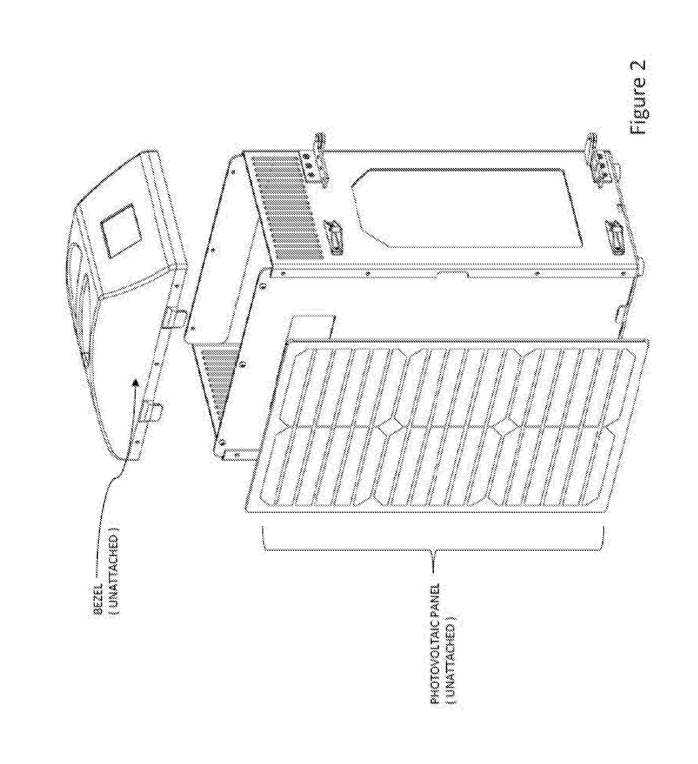
[0026] FIG. 2 is an isometric view with the top bezel and photovoltaic panel shown in a removed configuration.
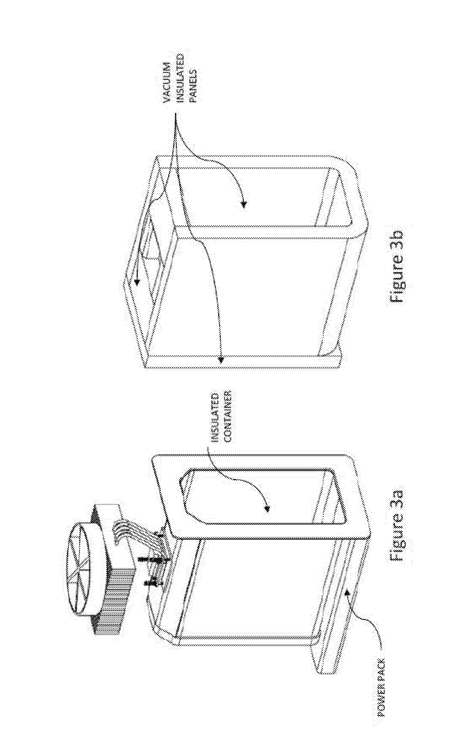
[0027] FIG. 3a shows the insulated container without the insulating panels surrounding it. At the bottom of the figure is shown the power pack which contains the rechargeable battery, the charge controller, and other power electronics. FIG. 3b shows the vacuum insulated panel assembly which surrounds the insulated container. FIG. 3C shows the attachment of the insulated door to the insulated container.
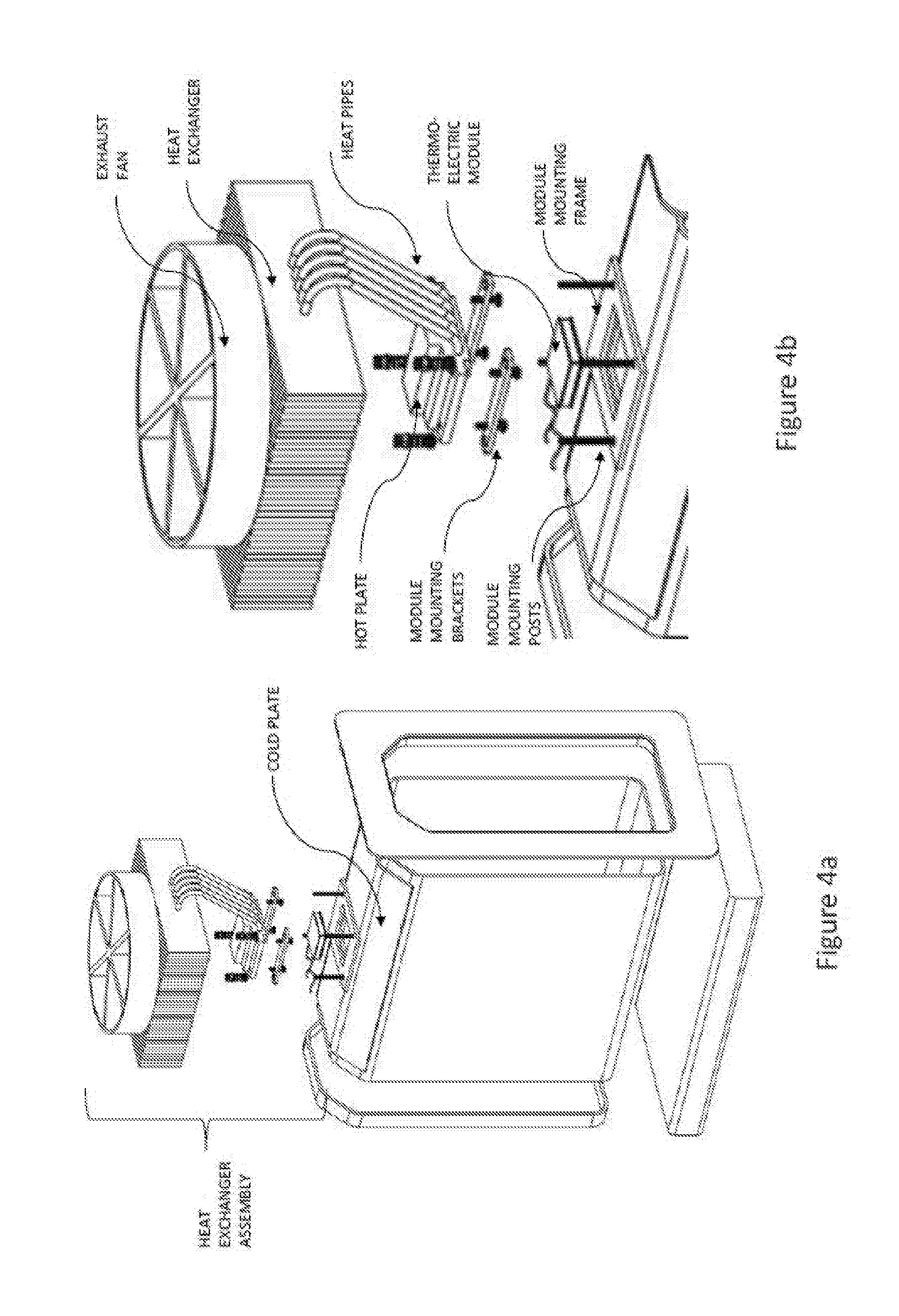
[0028] FIG. 4a is an exploded view of a variation of the portable refrigerator unit having the assembly of the heat exchanger on the insulated container with the TE module in mechanical contact with both the surface of the insulated container and the heat exchanger assembly.
[0029] FIG. 4b shows the detail of the heat exchanger assembly including the cold plate, the thermoelectric module, the module mounting frame, the module mounting posts, the module mounting brackets, the hot plate, the heat pipes, the heat exchanger and the exhaust fan. At the bottom of the assembly is shown the battery pack and charging elements of the assembly.
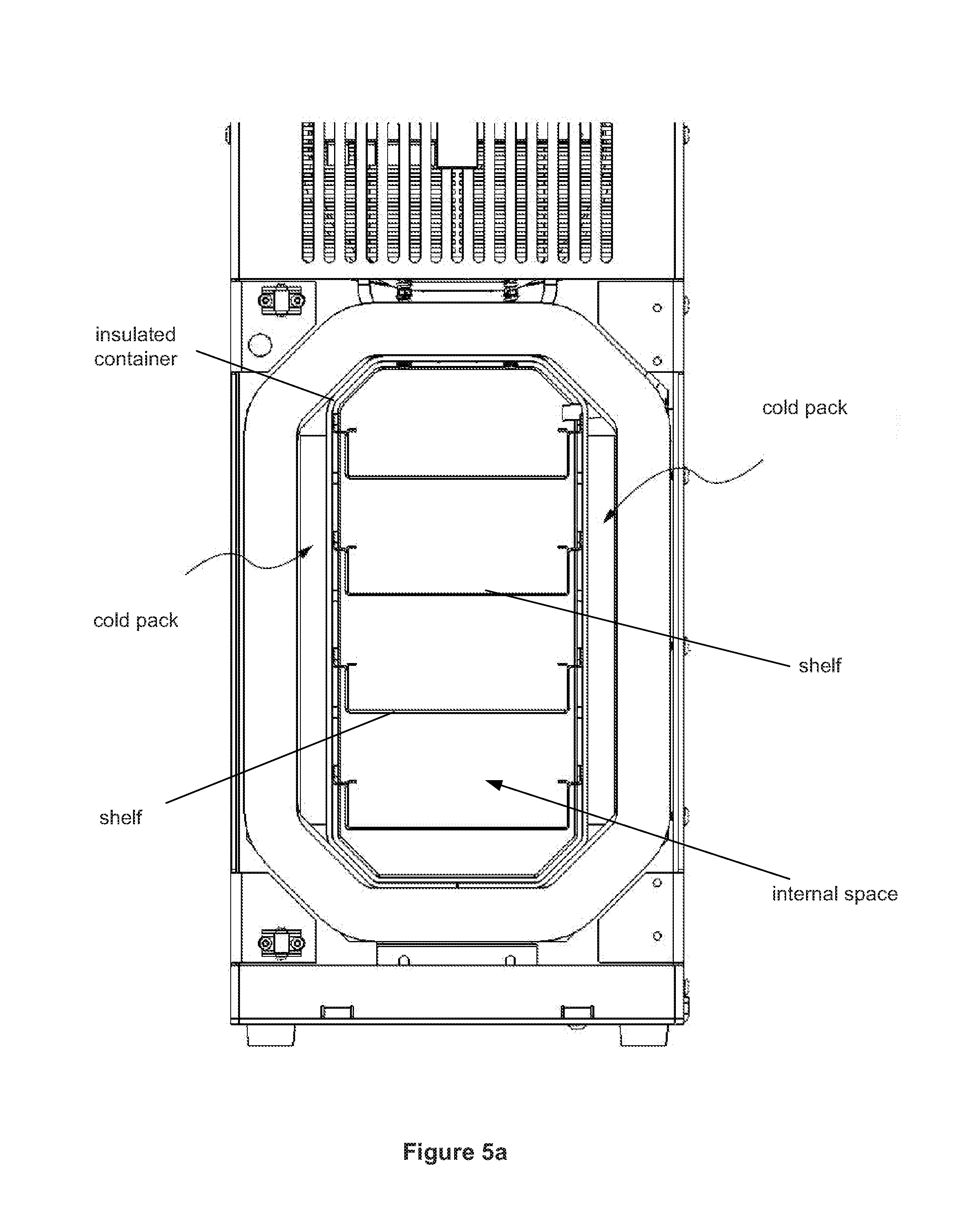
[0030] FIGS. 5a, 5b are cropped front and isometric views, respectively, of a variation of the refrigerator without the front door for illustrative purposes.
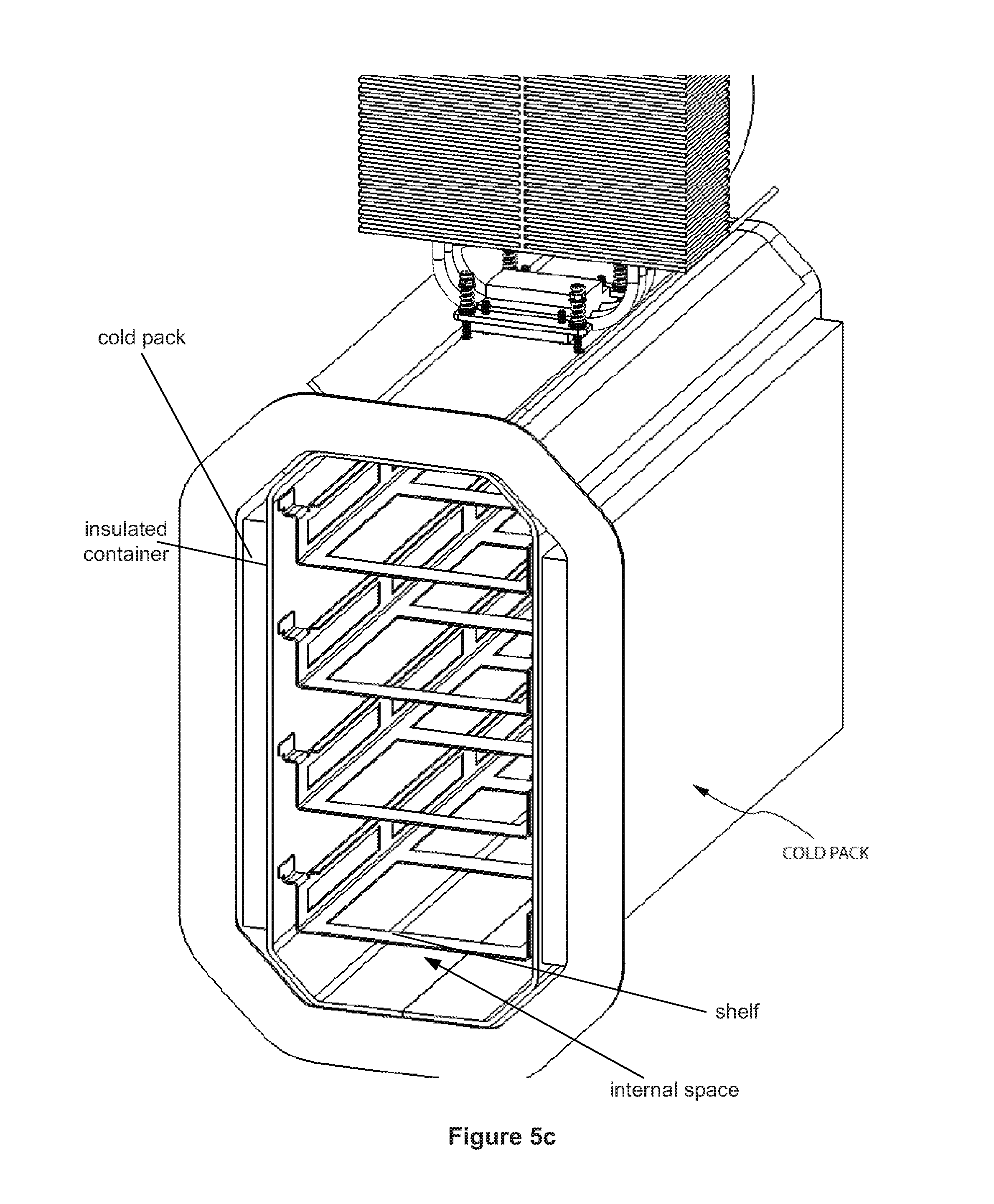
[0031] FIG. 5c is a cropped isometric view of the refrigerator of FIGS. 5a and 5b without the enclosure shown for illustrative purposes.
[0032] FIGS. 5d and 5e are cropper isometric and front section views, respectively, of the refrigerator of FIGS. 5a and 5b.
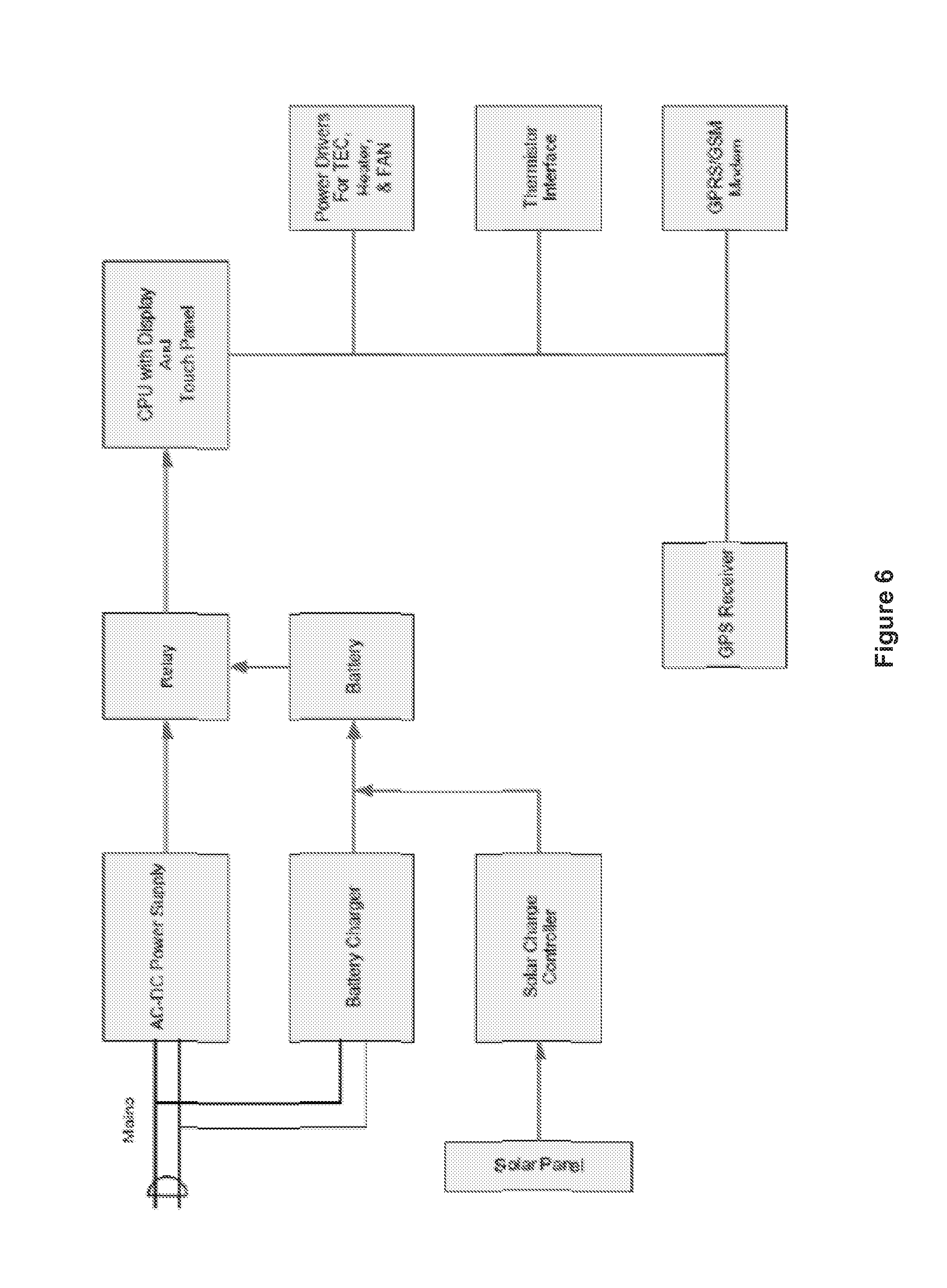
[0033] FIG. 6 provides an electrical schematic representative of the various electrical components in the system, their relation to each other, the connections between the components, and their relative functional roles in the system.
[0034] FIG. 7 is a table of exemplary performance specifications for the refrigerator.
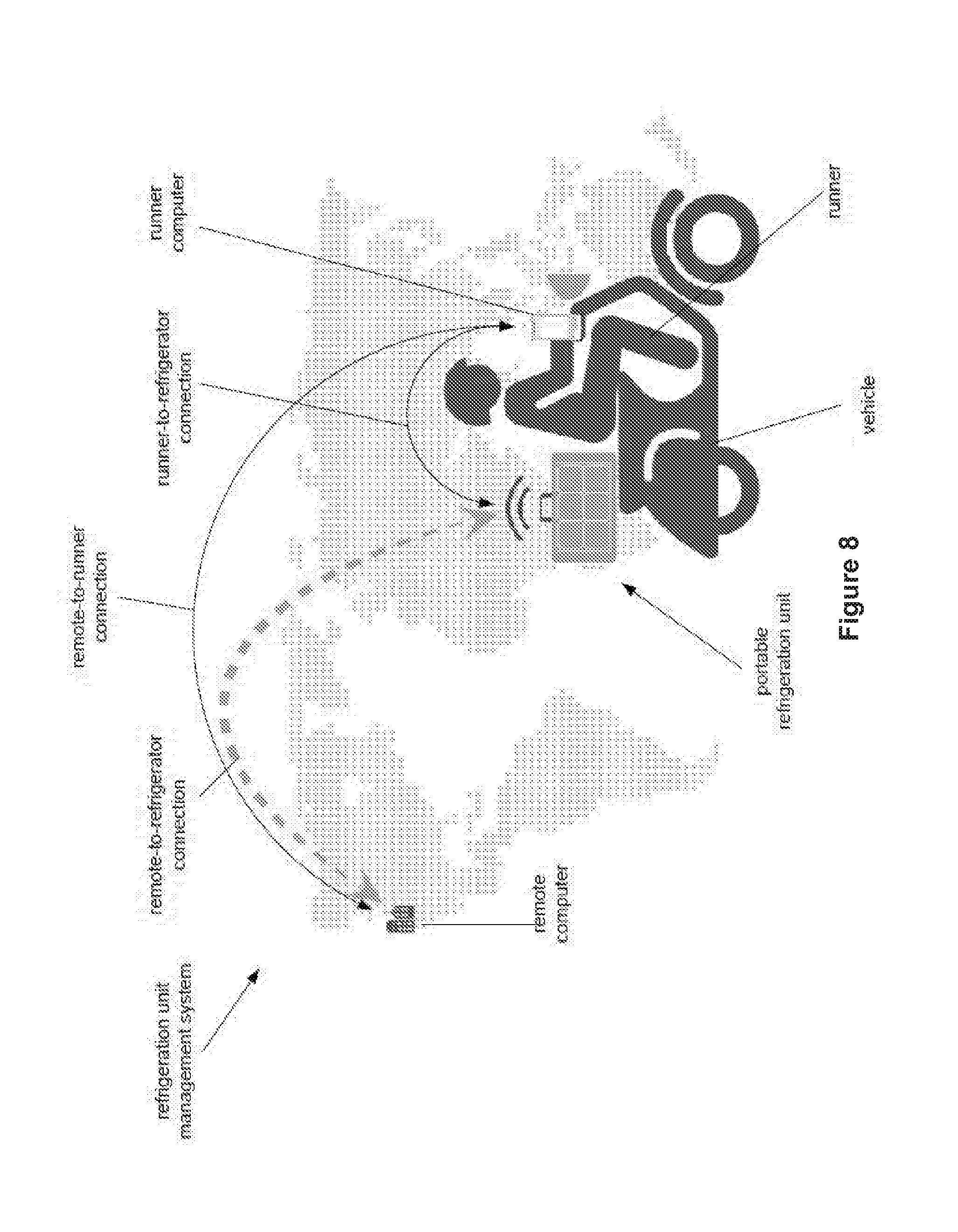
[0035] FIG. 8 is a schematic network diagram of a variation of the refrigeration unit management system overlaid on a map illustrating approximate exemplary geographical locations of the components of the system.
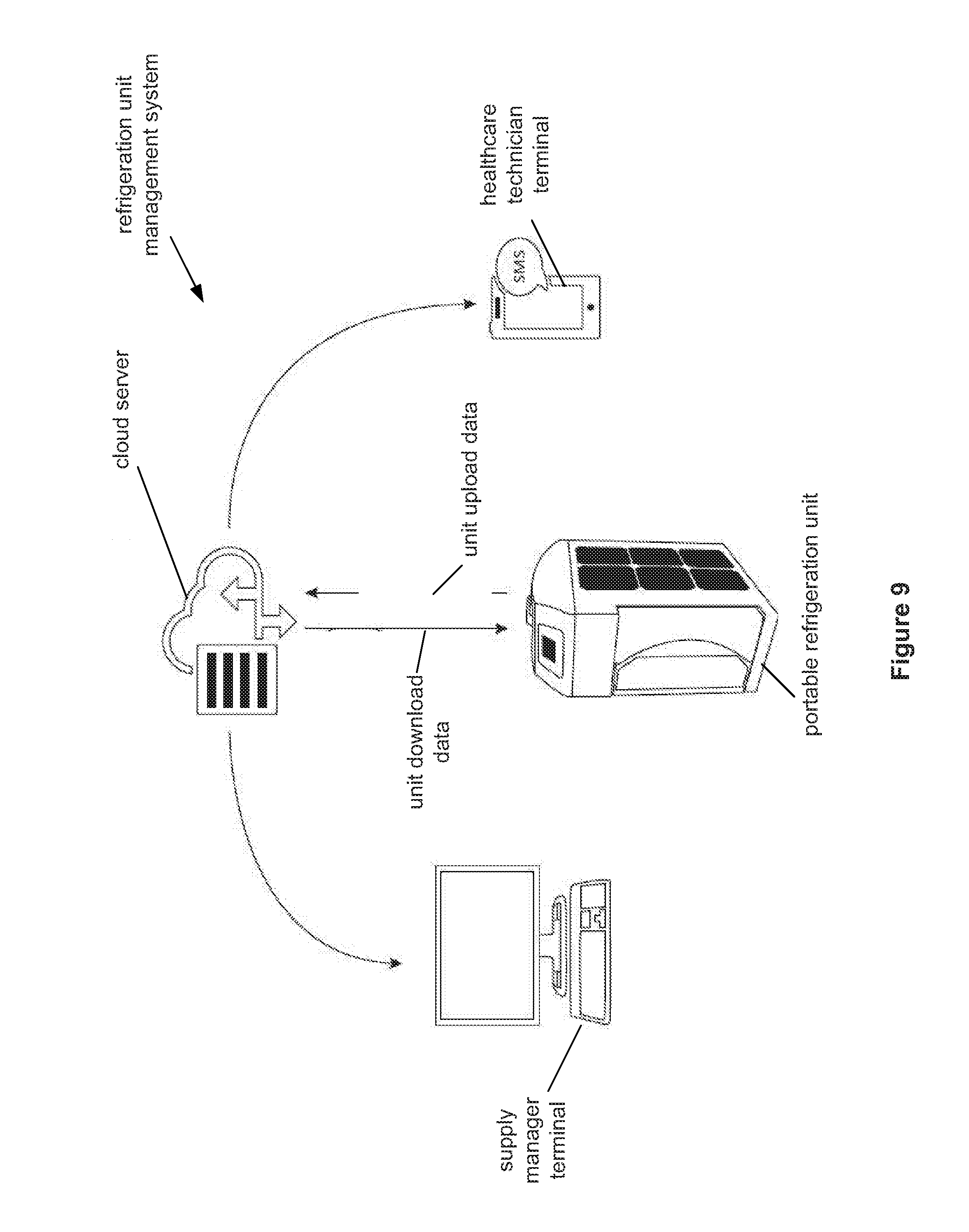
[0036] FIG. 9 is a schematic drawing of a variation of a networked refrigeration unit management system.
[0037] FIG. 10 illustrates a variation of a summary display for the unit interface screen, remote computer, runner computer, or variations thereof.
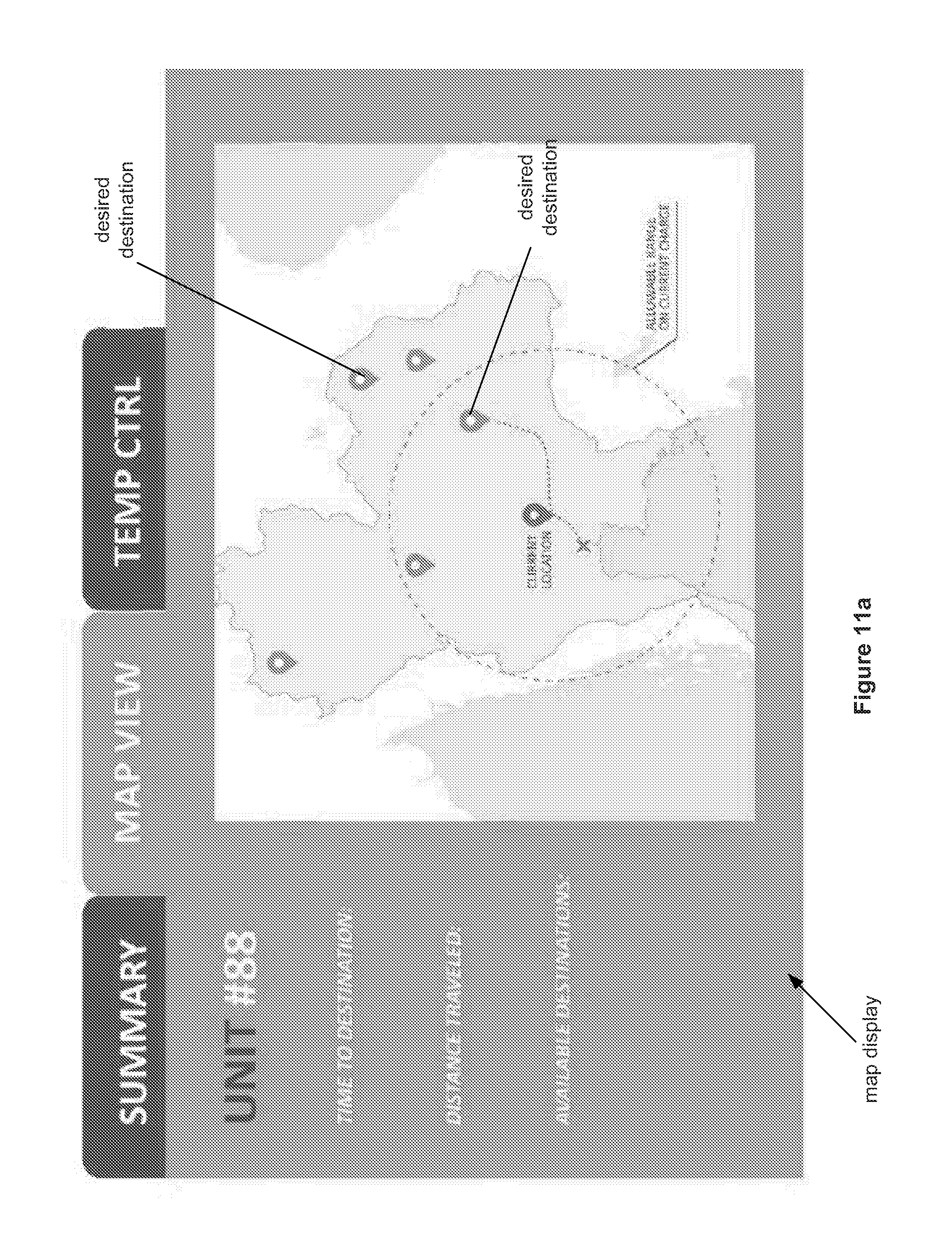
[0038] FIGS. 11a through 11c illustrate variations of a map display for the unit interface screen, remote computer, runner computer, or variations thereof.
[0039] FIGS. 12a through 12c illustrate variations of temperature control displays for the unit interface screen, remote computer, runner computer, or variations thereof.
DETAILED DESCRIPTION
[0040] FIGS. 1a, 1a' and 1a'' show a portable refrigeration unit (also referred to herein as a refrigerator) of approximately 30 inches in height, 10 inches in width, and 14 inches in depth, or less in dimensions. The portable refrigeration unit can contain an insulated container internal to the assembly that can have an approximate 4-12 liter volume, for example an 8 liter volume, cold chamber or internal space. The insulated container can be held within an enclosure assembly and has an insulated door to allow access to the contents of the insulated container. The insulated door can rotate about door hinges at both top and bottom of the door. The insulated door when pressed against the enclosure assembly can create a seal that keeps the cold internal temperature stable compared to the higher outside ambient temperature of the air. The refrigerator unit can have a detachable photovoltaic panel assembly comprised of photovoltaic cells. This photovoltaic panel assembly is used in the generation of electricity from incident sunlight falling on the photovoltaic cells. The photovoltaic panel assembly can be retained on the side of the portable refrigerator during transport through the use of panel mounting tabs that capture the top and bottom edge of the photovoltaic panel. The unit can have an AC outlet and/or plug and cord, for example for unit operation and on-grid charging. On top of the assembly is a bezel that provides a place for the graphical user interface screen to be placed and accessed.
[0041] As shown in FIG. 1a', the unit can have a touch screen user interface screen. The unit can have intake vents, such as a cooling intake. The internal space of chamber can have shelves, as shown in FIGS. 5a through 5e, and/or custom sections. The unit can have a carrying handle (obscured by the case in FIG. 1a') that can be foldable to lay flush against the top surface of the unit when the handle is not in use. The case of the unit can have a photovoltaic panel assembly or solar panel, for example hingedly attached to the remainder of the case so the solar panel can be rotated upward to be more directly facing the sun when a stronger charge is desired.
[0042] The unit can have an electrical power plug (e.g., an AC plug for attaching to an AC main power source). The plug can be on an extendable power cord and can retract and be obstructed by the solar panel when not extended.
[0043] FIG. 1a'' illustrates that the insulated door of the unit can rotate open, accessing the insulated container or internal space of the unit.
[0044] FIG. 1b shows the front of the portable refrigeration unit with the air intake or cooling intake slots for the heat exchanger exhaust circuit visible near the top of the system. The system show in 1b has the insulated door closed and the door latches shown in the locked position, thus holding the door closed under compression for transport.
[0045] FIG. 1c shows the right side of the enclosure for the portable refrigeration unit where the side material of the enclosure is made from sheet metal. This material could be aluminum, steel or another lightweight alloy suitable for durable, exterior use devices.
[0046] FIG. 1d shows the back of the portable refrigeration unit with the air intake slots disposed near the top of the assembly. On the back panel of the unit can also be found the AC power inlet for connection of a power cord. Next to the inlet for the power cord can be a fuse holder and a power switch for safety and operation of the unit during energizing.
[0047] FIG. 1e shows the top of the portable refrigeration unit which has a ventilated air exhaust in the top of the bezel. This exhaust area allows for hot air to be released from the heat exchanger assembly during operation and more specifically for the exhaust fan to vent the hot system as it operates. Above the heat exhaust area is a carrying handle integrated into the bezel at the top of the unit. This handle allows for the portable unit to be carried in a fashion similar to that of a suitcase. The portable refrigeration unit can weigh less than about 22 kg, for example from about 6 kg to about 22 kilograms depending on component selection, size of battery and insulated container volume. The unit can be used in the field for the delivery of cool items.
[0048] FIG. 2 shows the photovoltaic panel unmounted from the side of the unit assembly thus allowing for the panel to be placed at a distance from the unit to collect the sun's rays and generate electricity to charge the on board battery system. The distance this panel can be separated from the unit is determined by the length of hook up cable used between the photovoltaic panel and the unit. A typical hook up cable length might be from 5-15 meters, thus allowing for placement of the panel outside of a clinic area where the cables could be run through an open window to the portable refrigeration unit. The bezel is also shown unattached as it would need to be for initial assembly and possibly for servicing of the exhaust fan or to allow access to the microcontroller printed circuit board housed behind the user interface screen. The bezel would be removed to allow access to wiring, or to switch a sim card on the communications printed circuit hoard attached to the microcontroller PCB.
[0049] FIG. 3a represents the internal elements of the portable refrigeration system. The insulated container is shown without the surrounding vacuum insulated panel insulation assembly. On top of the insulated container assembly is the heat exchanger assembly. Disposed below the insulated container component of the assembly is the power pack assembly. The power pack contains the rechargeable batteries which may be of a lithium ion type (LiON) or a lithium iron (LiFE) material or of the more traditional lead acid variety. The batteries sit next to the charge controller and the system power supply that determines the proper charge levels for the batteries and converts incoming AC power to the appropriate DC power for use in the system.
[0050] FIG. 3b shows the vacuum insulated panel assembly of individual panels, both of a flat nature and in a bent configuration. These panels can be made from expanded foam, metallized film and/or aluminum foil which has been bonded and then sealed under vacuum thus creating highly effective insulation board materials. This vacuum insulated panel assembly can be used as a jacket for the insulated container portion of the device and keeps the internal portion of the system very cold as required to provide the appropriate level of cooling to the contents of the portable refrigeration system.
[0051] FIG. 3c shows the insulated door separate from the portable refrigeration system and demonstrates how the door can be mounted on the hinges and made to swing into place and close tight as is represented in the previous figures. The user interface screen located in the bezel part of the device has both touch screen capabilities and soft-key functionality that allows for changing input screens depending on user intention and stage of use. Behind the user interface screen can be a printed circuit board (PCB) containing the microcontroller for system level operation, monitoring, power adjustment and feedback in the form of temperature readings to the on board communication module that can execute tracking algorithms (including receiving satellite location data) for the unit and communication to the internet cloud.
[0052] FIG. 4a shows the thermoelectric module mounted to the external side of the insulated container. The top of the insulated container is composed of a metallic material such as aluminum to promote good conduction of the cooling effect of the thermoelectric module. This portion of the assembly is referred to as the cold plate because it is on the side receiving cold from the thermoelectric module. FIG. 4b shows the heat exchanger assembly and its attendant parts. The thermoelectric module, or TE module, is put in contact with the cold plate of the insulated container through use of a module mounting frame, module mounting posts, and module mounting brackets for use in compressing the TE module firmly against the cold plate on the top of the insulated container. This assembly of the TE module is often performed with a thermal paste to better assist in the conduction of heat energy away from the cold plate and to the side of the hot plate which is disposed in contact with, and on top of, the TE module.
[0053] FIG. 4b also shows the top side of the TE module in contact with the hot plate that is connected via heat pipes of highly conductive material to be in contact with the heat exchanger at the top of the system. This heat exchanger assembly is of a design especially suited for conducting large amounts of heat away from a relatively small area in an efficient and solid state manner whereby there is no movement of the hot plate or the heat pipes during normal operation save the possible changing in size of the components due to rapid increases in temperature. The heat exchanger at the top of the assembly is run through by the heat pipes such that heat conducted away from the hot plate is exhausted into the heat exchanger which is in turn cooled by a top mounted exhaust fan that sucks the heat out of the heat exchanger and sends it away from the portable refrigeration unit.
[0054] FIGS. 5a through 5e illustrate that the internal space or chamber of the insulated container can have one or more shelves. The shelves can oriented parallel with respect to each other and horizontal. The shelves can be slidably extended and removed from the internal space. The shelves can be locked into place inside of the internal space.
[0055] The refrigerator unit can have cold packs attached to the outside surface of the insulated container. The cold packs can each have a reservoir filled with 350 g of phase-change material (e.g., PCM-OM06P from RGEES, LLC of Arden, N.C.). The phase change material can change phase at 5.5 C. The cold packs can have high latent heat storage and can be safe to make contact with the temperature-sensitive load.
[0056] The cold packs can be rectangular, and can be attached to the sides, top, bottom, back, or combinations thereof of the insulated container. The cold packs can be attached to the insulated door. The cold packs can be slidably removed from the refrigerator unit. For example, warmer cold packs can be swapped for colder cold packs.
[0057] FIG. 6 shows the electronic components of the system and their function in a schematic layout representative of their connections and relative functionalities. The block diagram shows the AC mains inlet leading to the AC-DC power supply and converter. This component can provide DC power to the system through a relay. The AC mains can also be connected to a battery charger that charges the battery pack. The battery can then in turn provide DC power to the system through the relay. When the photovoltaic solar panel is connected and generating electricity, it can feed DC power into the solar charge controller which in turn can charge the battery. The battery then can run DC power to the system through the relay the same as when charged from AC mains.
[0058] The microcontroller central processing unit (CPU) can control the logic of the system and distributes the DC power to the system level components including the thermoelectric module, the resistance heater, and the exhaust fan. The microcontroller also sends small DC voltages to the thermistors which read the temperature of the interior of the insulated container and the ambient external temperature. The microcontroller is also connected to the communications module which includes a GPS receiver to determine global position via satellite and the GPRS/GSM modem that provides connectivity to the internet and cloud based servers that support the data acquisition aspects of the devices functionality.
[0059] The electronic system design for the portable refrigeration unit is based on a PIC24EP processor which can have a 320.times.240 TFT color display with touch panel. This provides the user interface for the unit and also monitors and controls the heating or cooling of the chilled chamber. The presence of the TE module allows for cooling of the insulated container. The likely addition of a small resistance heater in the insulated container also means that the system can be used to heat the contents enough to avoid any risk of freezing the contents.
[0060] Power MOSFETS connected to IO pins on the processor provide control for the thermoelectric module, a resistive heater, and the fan.
[0061] The temperature of the chilled chamber and the TE module heat sink are monitored with NTC thermistors connected to analog inputs on the processor. The resulting voltages are converted with the on-board Analog to Digital Converter (ADC) and the actual temperatures are calculated using the standard Steinhart-Hart algorithm and displayed.
[0062] The temperatures are sampled routinely and as an example at the rate of once per second and averaged by the firmware over a time range which could be 8 seconds.
[0063] The firmware is based on a periodic interrupt in the range of 1-100 times per second. In the case where it is 20 times per second as an example, this divides each second into 20 time slots. The various processor tasks are allocated to different time slots to even out the load on the processor and to allow for better power management. On each interrupt, the touch panel is sampled to determine if the user has made any inputs to the system.
[0064] Temperature control can be done with a simple on/off thermostat type of algorithm with a hysteresis of 0.1 C. The user has control of the set-point via a menu selection. The default could be at any temperature but would likely be at 5 C. When the temperature is above the set-point minus the hysteresis, the TE module is turned on. When the temperature drops below that point, the TE module is turned off. When the temperature rises above the set-point plus the hysteresis, the TE module is turned on again. This cycle can take from 30 seconds to 10 minutes and can keep the chamber temperature within +0.3 and -0.1 C of the set-point as an example.
[0065] The TE module heat exchanger temperature can also be controlled via the fan. If the heat exchanger temperature rises above a set maximum, 40 C for example, the fan can be turned on until the temperature drops to a safer level, perhaps below 35 C. This cycle can take a period of time from 10's of seconds to several minutes, depending on ambient temperature.
[0066] The CPU can have features to support a GSM (cell-phone type) modem and a GPS receiver. The combination of these two interfaces will allow the portable refrigeration system to determine its location via the GPS receiver and then use the GSM phone interface to report the position and the status of the system to a server. This will allow for the remote management of any number of portable refrigeration systems in the field via the internet and cloud connected computer servers.
[0067] The refrigerator can keep the inside of the chamber below 10.degree. C. without going below 0.degree. C., or another desired temperature target or range. The user can select a desired temperature range of approximately 6.degree. C. (2.degree. C. to 8.degree. C., for example), for example. The temperature measurement by a thermostat in the refrigerator can have a tolerance of about +/-1.degree. C.
[0068] The CPU can control the set-point of the temperature. The CPU can change the set-point of the temperature in the chamber depending on the power source or sources for the refrigerator and the desired temperature range. For example, if the refrigerator is running on mains power, the CPU can set the chamber temperature set-point at a temperature near the lower end (e.g., at 25% from the bottom of the range) or at the bottom of the selected temperature range. The chamber contents can then be chilled as much as possible so that when mains power is disconnected, the contents of the refrigerator have to warm up farther to exit the top of the desired range. This can result in a longer total run time.
[0069] If the refrigerator is running on battery power, the CPU can set the chamber temperature set-point to a temperature near the upper end of the selected temperature range (e.g., 75% from the bottom of the range). Battery power usage can be proportional to the difference between the internal and external temperature of the device, so allowing the internal temperature to rise can reduce the power drawn from the battery, extending the battery life.
[0070] When the refrigerator is powered by mains power, the internal battery can be charged at a high rate that can recharge the battery in approximately 4 hours. If the only external power available is solar power, the CPU can control the battery charge rate by reducing it from the rate during mains power connection to a level which the solar panel can support. This can depend on the orientation of the panel relative to the sun as well as the season, time of day, and atmospheric transparency, directly detected by sensors delivering the aforementioned data to the CPU, or merely by the CPU measuring input voltage from the solar panels. In this situation, the chamber temperature set-point can be set by the CPU as though running on battery power.
[0071] The power conditions can be checked by the CPU at least once per second and the internal settings can be adjusted accordingly.
[0072] FIG. 7 is a table of exemplary performance specifications for the refrigerator.
[0073] FIG. 8 illustrates that a refrigeration unit management system can have the portable refrigeration unit, a remote computer, a runner computer, or combinations thereof. The remote computer and/or runner computer can each be one or more servers, desktop or laptop computers, mobile devices such as smartphones, tablets, PDAs, barcode scanners, or combinations thereof.
[0074] The portable refrigeration unit can be in data communication with the remote computer over a remote-to-refrigerator connection. The runner computer can be carried by a runner or in a vehicle carrying the portable refrigeration unit. The runner computer can be in data communication with the remote computer over a remote-to-runner connection. The portable refrigeration unit can be in data communication with the runner computer over a runner-to-refrigerator connection. Any of the connections can be through local area networks, wide area networks, wifi, Bluetooth, cell-phone type connections (e.g., GSM), infrared, optical (e.g., bar code scanning), or combinations thereof.
[0075] The remote computer and/or runner computer can receive and/or request data from the portable refrigeration unit including the current and/or historical temperatures of the internal space of the unit and/or the ambient temperature outside of the unit (e.g., the unit can have digital thermometers inside and/or outside of the unit communicating with the CPU in the unit that can send out the temperatures to the remote and/or runner computers), the location of the unit, the items and their sizes stored in the unit (e.g., this can be entered manually into the unit's memory and/or determined by an optical scanner inside of the internal space, scanning the internal space and using image recognition software, and/or merely sending the image itself as a visual log of the contents of the internal space), or combinations thereof.
[0076] The remote computer and/or runner computer can send data to the refrigeration unit to adjust the unit settings (e.g., to extend battery life by increasing the temperature inside of the internal space, and/or reducing the duty cycling frequency of the unit).
[0077] The refrigeration unit and/or the remote computer can send a message to the runner computer to ask the runner to stop delivery to plug in the unit to a power source or expose the solar panels to the sun or another light source, for example when the remaining power in the batteries is below a level needed to reach the expected destination based on the current power load, speed of travel of the unit (based on the GPS readings), and length of travel remaining to destination, and also to alert the runner computer if there is a malfunction with the unit (e.g., from an unexpectedly high or low internal space temperature).
[0078] FIG. 9 illustrates that the portable refrigerator unit can be in a networked refrigeration system. The system can have nodes such as remote nodes, such as a server (e.g., a cloud server), supply manager terminal, healthcare technician terminal, and the local nodes such as the refrigerator unit, or combinations thereof. The nodes can all be in data communication with each other directly or indirectly, for example over the internet through the cloud server. The terminals can be desktop computers, laptop computers, handheld devices (e.g., tablets, smartphones), or combinations thereof.
[0079] The refrigerator unit can communicate (e.g., via satellite and/or the GPRS/GSM modem, and/or a direct, wired Ethernet connection) with the cloud server. The unit can upload unit upload data to the cloud server. The unit upload data can include, for example, location data including the present location and previous locations or path, battery charge level, internal temperature, external temperature, desired route, serial information to identify the unit and/or the driver/courier, manually entered notes (e.g., information entered by the driver regarding local environmental conditions), desired/preset internal temperature maximum, minimum, and/or temperature range, or combinations thereof.
[0080] An algorithm executing on a processor of the unit and/or cloud server, and/or another node in the system, can calculate the remaining distance range of the unit based on the location, desired route, battery charge, internal temperature, external temperature, and desired internal temperature maximum, minimum, and/or temperature range, or combinations thereof. (This calculation can also be performed by the algorithm on the unit itself.) The algorithm will calculate the estimated time the remaining battery charge can keep the internal temperature of the unit within the desired temperature range (e.g., including below the maximum temperature or above the minimum temperature), and then can estimate a distance range for the unit based on the projected speed of the unit. The cloud server can download unit download data to the unit including the distance range, and whether or not the unit is expected to arrive at a desired target location or endpoint before the internal temperature of the unit is no longer within the desired range, maximum, or minimum.
[0081] The cloud server (or the other nodes) can distribute any of the data disclosed herein to any of the nodes through a web interface, via e-mail, via text or SMS message (as shown for the healthcare technician interface), via automated voice messages as attachments with the aforementioned methods or via voice lines, or combinations thereof.
[0082] FIGS. 10, 11a through 11c, and 12a through 12c illustrate that the user interface screen, remote computer, runner computer, or combinations thereof, can display information provided by the unit and/or calculated by any of the nodes. The user interface screen can be accessed and viewed on the unit and/or on any of the nodes.
[0083] FIG. 10 illustrates that the display can be or have a summary display, screen or page. The summary page can show of the internal unit temperature with respect to time. The summary page can show the expected remaining operable time of the batteries. The operable time can be the remaining time for which the batteries can power the unit to keep the internal space below a desired temperature based on the remaining charge of the batteries. The summary page can show an expected time remaining to the delivery destination for the unit.
[0084] FIG. 11a illustrates that the display can be or have a map display, screen or page. The map display can illustrate a map showing the current location of the unit, the path including the starting location of the unit, the desired destinations for the unit, the estimated allowable range for the unit, and a projected path to a desired destination (e.g., a desired destination within the allowable estimated unit range). The allowable range can be the distance that the system calculates that the unit can travel based on the battery charge, desired internal temperature, external temperature, projected speed, and combinations thereof.
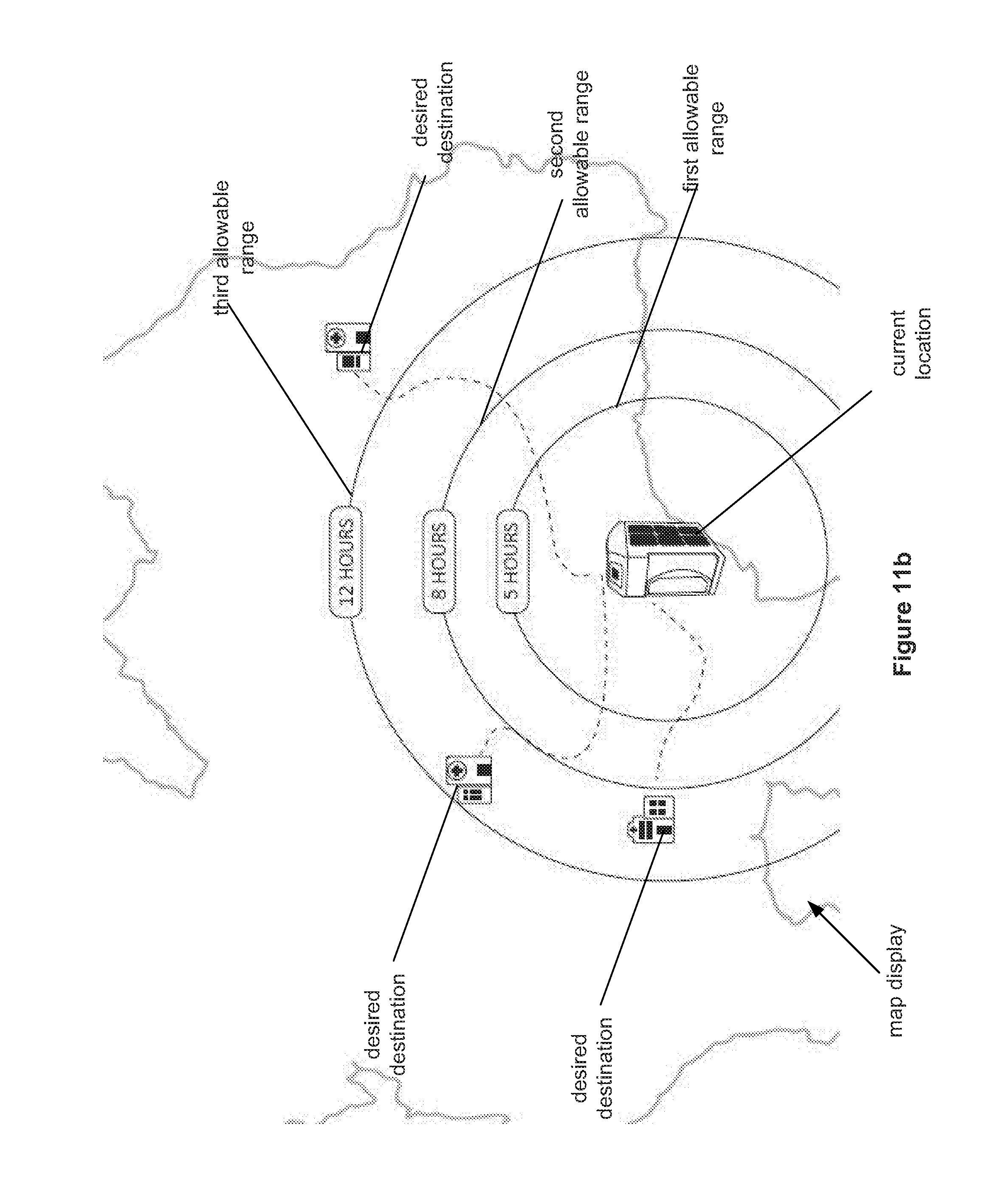
[0085] FIG. 11b illustrates that the map display can display various estimated allowable ranges based on different levels of battery charges. For example, a first allowable range can be shown if the battery has five hours of charge remaining based on the other data available. A second allowable range can be shown if the battery has eight hours of charge remaining based on the other data available. A third allowable range can be shown if the battery has twelve hours of charge remaining based on the other data available. The projected ranges can inform the runner or other users on the possible desire for additional charging of the battery to extend the range to a particular desired destination.
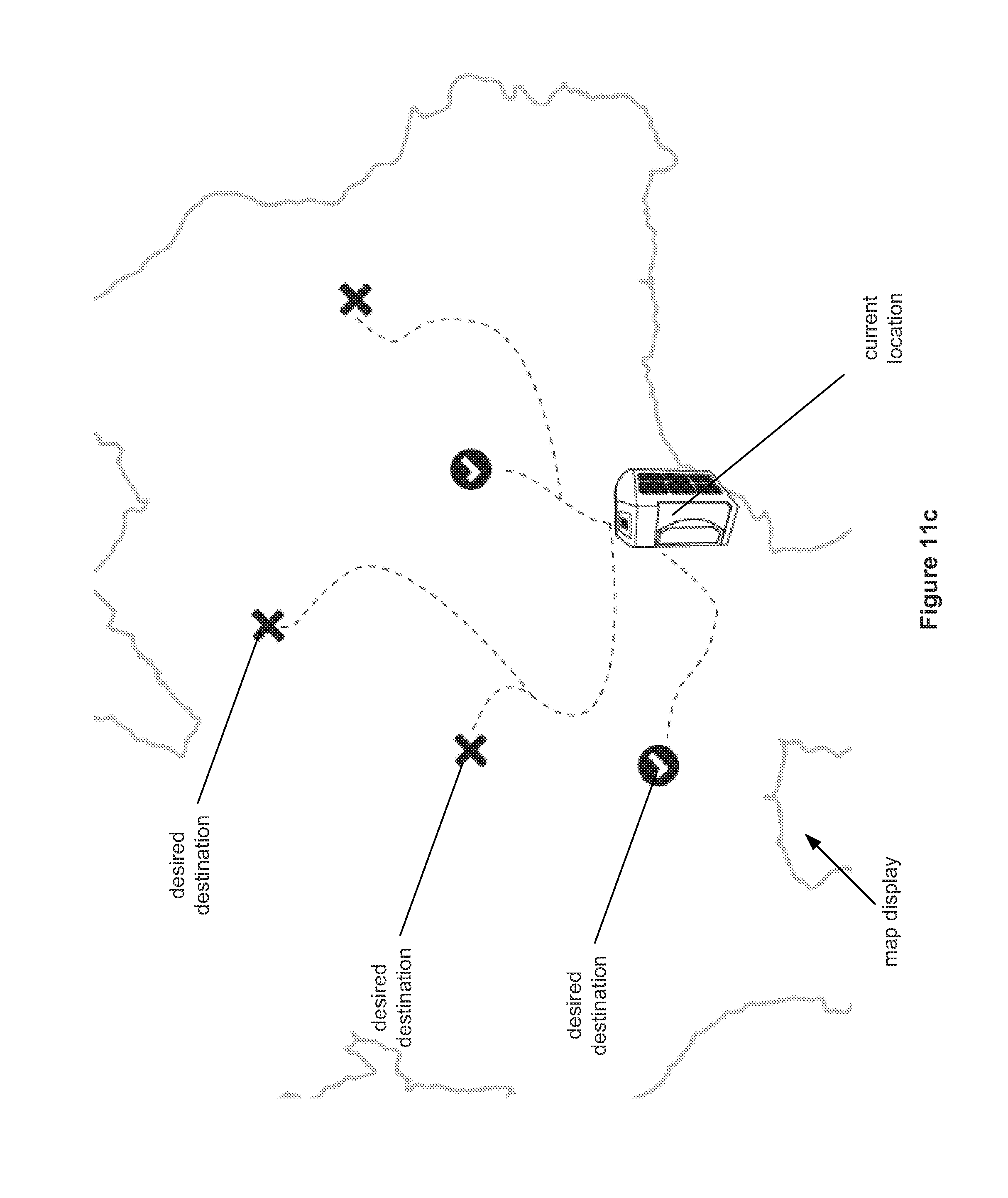
[0086] FIGS. 11a and 11b illustrate that the allowable range can be estimated as circles defining constant radii away from the current location of the unit. FIG. 11c illustrates that the system can calculate the allowable ranges based on expected speed and distance along particular routes, rather than as a constant radius. The system can calculate which desired destinations are within the allowable range (e.g., with check marks), and which desired destinations are not within the allowable range (e.g., with crosses or "X"s) based on the current battery charge and other data.
[0087] FIG. 12a illustrates that the display can be or have a first temperature control display, screen or page. The first temperature control page can show the current internal (inside of the internal space) and/or ambient temperature (around the outside) of the unit, the desired temperature range of the internal space, the strength of the network communication connection, the percent of battery charge remaining, or combinations thereof. The first temperature control page can have a button (e.g., "SETTINGS") to advance to the second temperature control page.
[0088] FIG. 12b illustrates that the display can be or have a second temperature control display, screen or page. The second temperature control page can show the hours of operation of the unit thus far in the trip (e.g., "HRS OPS") which can be manually or automatically reset before each trip begins, the currently set temperature range, controls for adjusting the temperature range (e.g., "+" and "-", for increasing and decreasing, respectively, the temperature by a single degree), the newly set temperature range, the strength of the network communication connection, the percent of battery charge remaining, or combinations thereof. In the second temperate control page, the user can modify the desired temperature range for the internal space. The second temperature control page can have a button (e.g., "CONTINUE") to advance to the third temperature control page.
[0089] FIG. 12c illustrates that the display can be or have a third temperature control display, screen or page. The third temperature control page can show the maximum and minimum temperatures experienced by the internal space since the beginning of the trip for the unit (e.g., the maximum and minimum trip temperatures can be manually or automatically reset before departing for each trip), a hold over time (i.e., the expected remaining operable time of the batteries to keep the internal space within the desired temperature range), the strength of the network communication connection, the percent of battery charge remaining, or combinations thereof.
[0090] The display can cycle automatically and/or manually through the first, second, and third temperature control pages.
[0091] The variations above are for illustrative purposes and it will be apparent to those skilled in this art that various equivalent modifications or changes according to the idea of and without departing from the disclosing and teaching herein shall also fall within technical scope of the appended claims. For example, any of the materials disclosed herein can be used to make any of the elements.
[0092] Systems and methods that have elements that can be used in combination with the disclosure herein include those taught in U.S. Pat. Nos. 6,929,061, 7,728,711, 8,026,792, 8,280,550, 9,182,155, and U.S. Patent Pub. Nos. 2009/0139248, 2012/0036869, 2015/0143823, all of which are incorporated by reference herein in their entireties.
[0093] Any elements described herein as singular can be pluralized (i.e., anything described as "one" can be more than one), and plural elements can be used individually. Any species element of a genus element can have the characteristics or elements of any other species element of that genus. The term "comprising" is not meant to be limiting. The above-described configurations, elements or complete assemblies and methods and their elements, and variations of aspects thereof can be combined and modified with each other in any combination.
* * * * *
D00000
D00001
D00002
D00003
D00004
D00005
D00006
D00007
D00008
D00009
D00010
D00011
D00012
D00013

D00014

D00015
D00016

D00017
D00018
D00019

D00020
D00021
D00022
D00023

XML
uspto.report is an independent third-party trademark research tool that is not affiliated, endorsed, or sponsored by the United States Patent and Trademark Office (USPTO) or any other governmental organization. The information provided by uspto.report is based on publicly available data at the time of writing and is intended for informational purposes only.
While we strive to provide accurate and up-to-date information, we do not guarantee the accuracy, completeness, reliability, or suitability of the information displayed on this site. The use of this site is at your own risk. Any reliance you place on such information is therefore strictly at your own risk.
All official trademark data, including owner information, should be verified by visiting the official USPTO website at www.uspto.gov. This site is not intended to replace professional legal advice and should not be used as a substitute for consulting with a legal professional who is knowledgeable about trademark law.