Capsule For A Valve And Valve
Lassen; Simon Ahrens ; et al.
U.S. patent application number 16/065976 was filed with the patent office on 2019-01-03 for capsule for a valve and valve. The applicant listed for this patent is Danfoss A/S. Invention is credited to Klaus Halldorsson, Bjarne Hechmann Lagoni, Simon Ahrens Lassen, Jens Erik Rasmussen.
| Application Number | 20190003607 16/065976 |
| Document ID | / |
| Family ID | 55069792 |
| Filed Date | 2019-01-03 |


View All Diagrams
| United States Patent Application | 20190003607 |
| Kind Code | A1 |
| Lassen; Simon Ahrens ; et al. | January 3, 2019 |
CAPSULE FOR A VALVE AND VALVE
Abstract
The invention relates to a capsule for a valve as well as to a valve comprising such a capsule. The task of the present invention is to provide a valve in which tight tolerances for construction can be achieved and the assembly of the valve is simplified. According to the present invention the above task is solved by a capsule (1) for a valve comprising at least one diaphragm (2), a valve seat (3), a capsule inlet (5) and a capsule outlet (6). The valve seat (3) is openable and closable to permit or stop a fluid flow from the capsule inlet (5) to the capsule outlet (6). The above task is also solved by a capsule (1) for a valve that comprises at least one diaphragm (2), a valve seat (3), a capsule inlet (5) and a capsule outlet (6), wherein the capsule (1) is structured and arranged to control the position of a pilot valve element external to the capsule (1). The above task is also solved by a valve (10) comprising a valve housing (15), wherein a capsule (1) of the above kind is arranged in the valve housing (15).
| Inventors: | Lassen; Simon Ahrens; (Kolding, DK) ; Halldorsson; Klaus; (Kolding, DK) ; Rasmussen; Jens Erik; (Grasten, DK) ; Lagoni; Bjarne Hechmann; (Kolding, DK) | ||||||||||
| Applicant: |
|
||||||||||
|---|---|---|---|---|---|---|---|---|---|---|---|
| Family ID: | 55069792 | ||||||||||
| Appl. No.: | 16/065976 | ||||||||||
| Filed: | January 3, 2017 | ||||||||||
| PCT Filed: | January 3, 2017 | ||||||||||
| PCT NO: | PCT/EP2017/050093 | ||||||||||
| 371 Date: | June 25, 2018 |
| Current U.S. Class: | 1/1 |
| Current CPC Class: | F16K 17/085 20130101; F16K 27/0236 20130101 |
| International Class: | F16K 17/08 20060101 F16K017/08; F16K 27/02 20060101 F16K027/02 |
Foreign Application Data
| Date | Code | Application Number |
|---|---|---|
| Jan 4, 2016 | EP | 16150039.2 |
Claims
1-17. (canceled)
18. A capsule for a valve wherein the capsule comprises at least one diaphragm, a valve seat, a capsule inlet, a capsule outlet, and a spring which is arranged in the capsule to load the valve element, wherein the spring is arranged on the side of the at least one diaphragm facing the capsule outlet.
19. (canceled)
20. The capsule according to claim 18 wherein the capsule comprises a capsule top and a capsule bottom, wherein at least one diaphragm is fixed at a radially outer end of the diaphragm between the capsule top and the capsule bottom.
21. The capsule according to claim 18, wherein the at least one diaphragm also has the function of a valve element to open or close the valve seat.
22. The capsule according to claim 18, wherein a valve element is arranged in the capsule in addition to the at least one diaphragm to open or close the valve seat.
23. The capsule according to claim 18, wherein the capsule comprises at least one thrust pad arranged at a first face of the at least one diaphragm opposite to a second face of the at least one diaphragm facing the valve seat.
24. The capsule according to claim 23, wherein the capsule comprises an aperture facing the thrust pad.
25. The capsule according to claim 24, wherein the thrust pad comprises a converging bore on a side facing the aperture.
26. (canceled)
27. (canceled)
28. A valve comprising a valve housing, wherein a capsule according to claim 18 is arranged in the valve housing.
29. The valve according to claim 28, wherein the valve comprises a presetting mechanism.
30. The valve according to claim 29, wherein the presetting mechanism comprises a spring mechanism with an adjustable presetting force.
31. The valve according to claim 29, wherein the presetting mechanism comprises a pressure port to adjust pressure on the side of the diaphragm opposite to the valve seat.
32. The valve according to claim 30, wherein the presetting mechanism comprises a stepper motor to adjust the presetting force of the spring mechanism.
33. The valve according to claim 28, wherein the valve is a pilot valve that comprises a pilot valve element external to the capsule, wherein the pilot valve element is actuatable by a displacement of the valve element in the capsule.
34. The valve according to claim 28, wherein the first face of the at least one diaphragm is loaded by a presetting pressure while the second face of the at least one diaphragm is loaded by a pressure from the capsule inlet(s).
Description
CROSS-REFERENCE TO RELATED APPLICATION
[0001] This application is a National Stage application of International Patent Application No. PCT/EP2017/050093, filed on Jan. 3, 2017, which claims priority to European Patent Application No. 16150039.2, filed on Jan. 4, 2016, each of which is hereby incorporated by reference in its entirety.
TECHNICAL FIELD
[0002] The invention relates to a capsule for a valve as well as to a valve.
BACKGROUND
[0003] In many kinds of valves diaphragms are used to separate pressure chambers to allow a partial or complete pressure control of the valve. For example, pilot valves are often at least partially pressure regulated and comprise two or more pressure chambers that are separated by a diaphragm. The diaphragm can either comprise or cooperate with a valve element to close or open a valve seat depending on the pressure difference between the pressure chambers.
[0004] The diaphragm is usually fixed between parts of the valve housing when assembling the valve.
[0005] However, it can be difficult to achieve tight tolerances in construction and consequently a precise opening behavior this way. Furthermore, the known valves comprising diaphragms usually cannot be serviced and need to be replaced in case of a malfunction.
SUMMARY
[0006] The task underlying the present invention is therefore to provide valve parts for a valve as well as a valve that can be easier assembled and disassembled and that allows to achieve tighter tolerances in construction.
[0007] According to a first aspect of the present invention the above task is solved by a capsule for a valve that comprises at least one diaphragm, a valve seat, a capsule inlet and a capsule outlet, wherein the valve seat is openable to permit a fluid flow from the capsule inlet to the capsule outlet.
[0008] According to a second aspect of the present invention the above task is solved by a capsule for a valve that comprises at least one diaphragm, a valve seat, a capsule inlet and a capsule outlet, wherein the capsule is structured and arranged to control the position of the pilot valve element external to the capsule.
[0009] According to the two above aspects of the present invention the parts which usually require the tightest tolerances are therefore arranged in a capsule. Consequently, this capsule can be preassembled with a manufacture method that allows tighter tolerances. Afterwards the capsule can be inserted into a valve by manual assembly. Similarly, if a valve comprising such a capsule needs to be serviced, the complete capsule can be replaced which speeds up the servicing and reduces the risk of an incorrect or imprecise reassembly of the valve. Consequently, both the maintenance interval as well as the overall lifetime of a valve comprising a capsule according to the invention is increased. The capsule may comprise one, two, three or more diaphragms. Preferably, the diaphragms are stacked on top of each other. This has the advantage that a standard diaphragm can be used and the number of the standard diaphragms can be chosen according to the required strength and flexibility. The capsule can comprise one, two, three, four or more capsule inlets.
[0010] According to the first aspect, the valve seat is openable to permit a fluid flow from the capsule inlet to the capsule outlet, wherein the valve seat is closable to stop a fluid flow from the capsule inlet to the capsule outlet. In this case the capsule provides the main fluid path through the valve. The capsule may either be used for a pilot valve or may be part of a main valve.
[0011] According to the second aspect of the present invention the capsule does not constitute the "core" of the valve with the main flow path through the valve but rather may be part of a control and/or presetting mechanism for a main valve external to the capsule. The capsule may in this case serve to transform pressure forces resulting from a pressure difference over the diaphragm into a force on a valve element external to the capsule.
[0012] In a preferred embodiment the capsule comprises a capsule top and a capsule bottom, wherein at least one diaphragm is fixed at a radially outer end of the diaphragm between the capsule top and the capsule bottom. Preferably, two, three or more diaphragms are stacked on top of each other and fixed collectively at a radial outer end of the diaphragms between the capsule top and the capsule bottom. The use of a capsule top and a capsule bottom keeps the number of parts of the capsule small, while allowing a simple assembly of the capsule. Preferably, both the capsule inlet as well as the capsule outlet are arranged in either the capsule top or the capsule bottom. This way it is ensured that both the capsule inlet and the capsule outlet are connected to the same pressure chamber.
[0013] It is preferred if at least one diaphragm also has the function of a valve element to open or close the valve seat. In this embodiment one may dispense with the use of a dedicated valve element. This on the one hand allows for a more compact construction of the capsule and on the other hand allows to dispense with a dedicated valve element as well as a spring element for loading the valve element.
[0014] Alternatively, a valve element is arranged in the capsule in addition to the at least one diaphragm. Preferably, the valve element is arranged to open or close the valve seat. In this case a dedicated valve element is arranged in the capsule in addition to the at least one diaphragm. The valve element is preferably loaded by a spring element. However, the valve element can also serve to actuate a valve element external to the capsule, for example, by engaging a pin connected to the valve element.
[0015] It is preferred if the capsule comprises at least one thrust pad arranged at a first face of the at least one diaphragm opposite to a second face of the at least one diaphragm facing the valve seat. Such a thrust pad can for example allow a presetting mechanism of the valve to engage the capsule. Such a presetting mechanism for example allows to choose the minimum pressure difference between the two sides of the diaphragm necessary to open the valve. In case several stacked diaphragms are used the first face and the second face denote the surfaces of the outermost diaphragms.
[0016] It is preferred if the capsule comprises an aperture facing the thrust pad. Such an aperture allows a presetting mechanism of the valve to engage the thrust pad. At the same time such an aperture can allow a communication of pressure from one of the pressure chambers of the capsule to the valve. Depending on the valve this can either be the atmospheric pressure or a controllable presetting pressure of the valve.
[0017] It is preferred if the thrust pad comprises a converging bore on a side facing the aperture. This for example allows to center a presetting mechanism engaging the thrust pad. The assembly of the valve comprising a capsule according to the invention is thus simplified.
[0018] It is furthermore preferred if a spring is arranged in the capsule to load the valve element. Preferably, the spring is a wave spring. The spring is preferably arranged on the side of the at least one diaphragm facing the capsule inlet and/or the capsule outlet. The use of a spring to load to valve element is in particular preferable if the valve is used in a refrigeration system in which the fluid pressure can be lower than the atmospheric pressure. In this case the additional spring force ensures that the valve can be kept open even if the pressure on the side of the diaphragm facing the capsule inlet is lower than on the side of the diaphragm opposite the capsule inlet. An example of a refrigeration system operating with fluid pressures below atmospheric pressure are ammonia refrigeration systems.
[0019] In an embodiment, a recess is arranged in the valve seat to allow a pressure to be communicated across the valve seat at all times. This embodiment may allow the same pressure to be present at the second surface of the diaphragm as is present at the capsule outlet irrespective of the position of the valve element relative to the valve seat.
[0020] The above task is also solved by a valve comprising a valve housing, characterized in that a capsule according to any of the above embodiments is arranged in the valve housing. Preferably, the capsule is fixed between two parts of the valve housing of the valve.
[0021] It is preferred if the valve comprises a presetting mechanism. Such a presetting mechanism allows to choose the pressure differential between the pressure chambers on both sides of the at least one diaphragm that is necessary to keep the valve open. Such a presetting mechanism may for example engage the thrust pad mechanically or allow to change the pressure on one side of the at least one diaphragm.
[0022] Preferably, the presetting mechanism comprises a spring mechanism with an adjustable presetting force. The spring mechanism may to this end engage the thrust pad and in particular the converging bore of the thrust pad. The spring mechanism may be manually adjustable or may be adjustable via an electric actuator like a stepper motor.
[0023] In a further preferred embodiment the presetting mechanism comprises a pressure port to adjust the pressure on the side of the diaphragm opposite to the valve seat. This way the minimum pressure at the capsule inlet side of the diaphragm necessary to open the valve may be adjusted. This provides an override option to open or close the valve if necessary. If no pressure port is used the pressure on the side of the diaphragm opposite to the capsule inlet is preferably atmospheric pressure.
[0024] It is furthermore preferred if the presetting mechanism comprises a stepper motor to adjust the presetting force of the spring mechanism. This has the advantage that the minimum pressure difference between the two sides of the diaphragm necessary to open the valve can be adjusted and controlled externally for example by a control unit connected to the stepper motor.
[0025] It is furthermore preferred if the valve housing comprises a valve inlet and a valve outlet, wherein the valve inlet is connected to the capsule inlet and the valve outlet is connected to the capsule outlet. In this case, the main fluid path through the valve leads through the capsule.
[0026] Preferably, the valve is a pilot valve that comprises a valve element external to the capsule, wherein the pilot valve element is actuatable by a displacement of the valve element in the capsule. The valve element and the pilot valve element preferably are indirectly connected by a pin. The valve element can be fixed to one end of the pin. The valve element in the capsule can abut the opposite end of the pin. In this embodiment the main fluid path through the pilot valve may not lead through the capsule. The capsule may in this case be used to control the opening and closing of the valve by actuating the valve element towards a valve seat external to the capsule.
[0027] It is preferred if a first face of the at least one diaphragm is loaded by a presetting pressure while a second face of the at least one diaphragm is loaded by a pressure from the capsule inlet. The presetting pressure may for example be atmospheric pressure or an adjustable pressure provided by a pressure port of the presetting mechanism.
BRIEF DESCRIPTION OF THE DRAWINGS
[0028] Preferred embodiments of the invention are now described with reference to the figures, wherein:
[0029] FIG. 1 shows a cut view of a first embodiment of a capsule according to the invention,
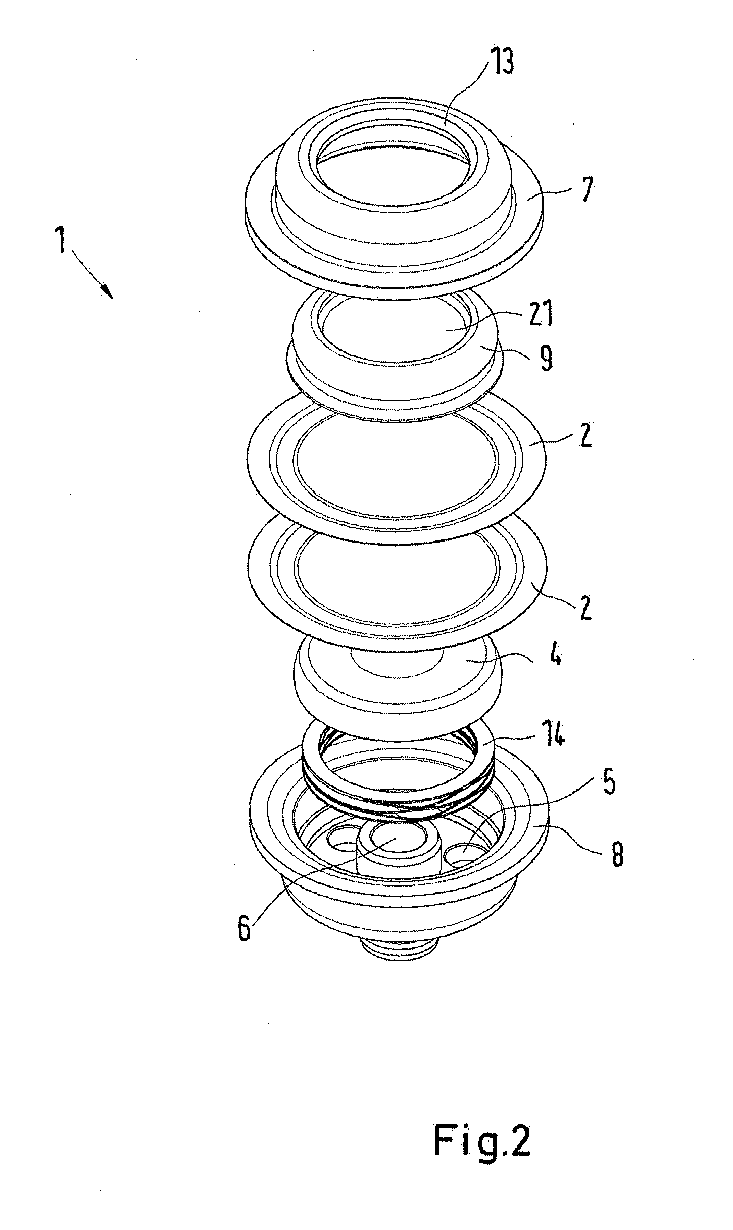
[0030] FIG. 2 shows an exploded view of a capsule according to the first embodiment,
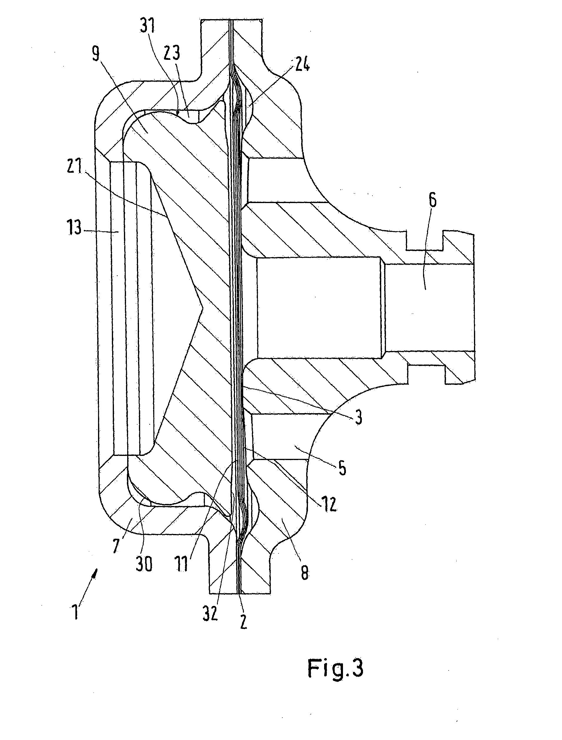
[0031] FIG. 3 shows a cut view of a second embodiment of a capsule according to the invention,
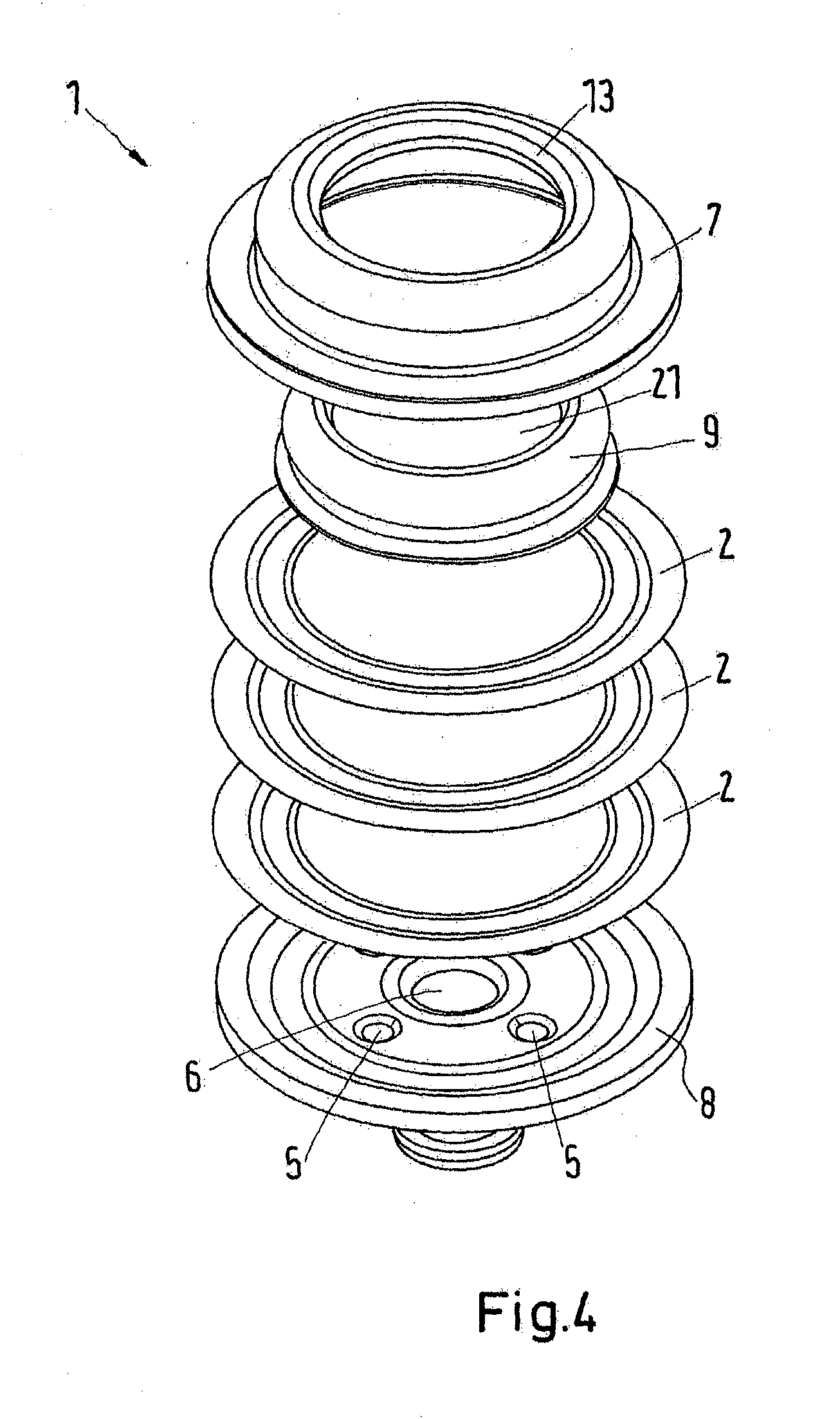
[0032] FIG. 4 shows an exploded view of a capsule according to the second embodiment,
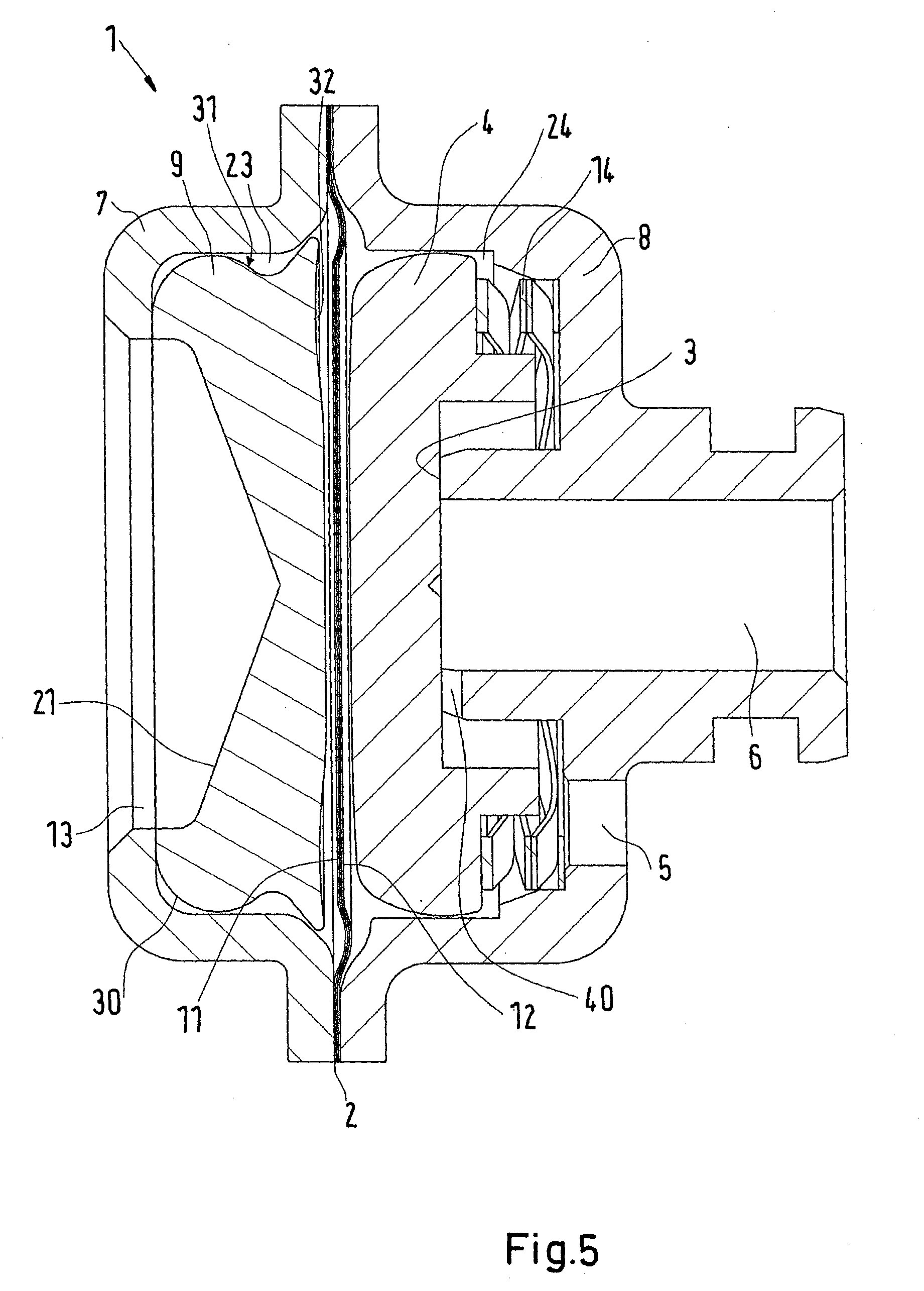
[0033] FIG. 5 shows a cut view of a third embodiment of a capsule according to the invention
[0034] FIG. 6 shows an exploded view of a capsule according to the third embodiment,
[0035] FIG. 7 shows a spring as used in a capsule according to the first and third embodiments,
[0036] FIG. 8 shows a fourth embodiment according to the invention,
[0037] FIG. 9 shows a fifth embodiment according to the invention,
[0038] FIG. 10 shows a sixth embodiment according to the invention, and
[0039] FIG. 11 shows a seventh embodiment according to the invention,
[0040] FIG. 12 shows an eighth embodiment according to the invention.
DETAILED DESCRIPTION
[0041] FIGS. 1 and 2 show a first embodiment of a capsule 1 according to the invention. The capsule 1 comprises at least one diaphragm 2, in this case two diaphragms 2. The diaphragms 2 are fixed to the capsule 1 at circumferential ends of the diaphragms 2. Here the diaphragms 2 are fixed between a capsule top 7 and a capsule bottom 8 at the outer ends of the diaphragms 2. The capsule top 7 and the capsule bottom 8 can be welded together by laser welding. The rest of the diaphragms 2 and in particular a central portion of the diaphragms 2 can move more or less freely inside the capsule 1. The capsule 1 furthermore comprises a valve seat 3 as well as a valve element 4. The valve element 4 is loaded by a spring 14. The spring 14 rests against the capsule bottom 8 at the end of the spring opposite to the valve element 4. The spring 14 here is a wave spring that is shown in more detail in FIG. 7.
[0042] The capsule 1 in this embodiment comprises two capsule inlets 5 as well as one capsule outlet 6.
[0043] The thrust pad 9 comprises a converging bore 21 that is aligned with an aperture 13 of the capsule top 7. This way a presetting mechanism of the valve can engage the thrust pad 9. The capsule 1 comprises two pressure chambers 23, 24 arranged on either side of the diaphragms 2. In the shown cut view of FIG. 1 the diaphragms 2 are in a neutral position, which they will usually not assume during operation of the valve because the pressure difference between the pressure chambers 23, 24 will almost always be non-zero. The valve element 4 will be lifted from the valve seat to open a fluid flow from the capsule inlets 5 to the capsule outlet 6 when the force of the spring 14 is larger than the differential pressure force acting on the valve element 4 through the diaphragm 2 as well as an optional presetting force that can act on the thrust pad 9 via a presetting mechanism that will later be described in more detail. In particular in ammonia refrigeration systems the fluid pressure at the inlet side of the diaphragm 2 can be well below atmospheric pressure, so the spring 14 may have to overcome a differential pressure force.
[0044] The thrust pad 9 is arranged in the pressure chamber 23. The thrust pad 9 is arranged neighboring a first face 11 of the diaphragms 2 opposite to the valve seat 3. The valve element 4 on the other hand is arranged neighboring a second face 12 of the diaphragms 2 in the pressure chamber 24.
[0045] The thrust pad 9 has a cylinder like shape. A rounded circumferential corner 30 of the thrust pad 9 between a side facing the aperture 13 and a radially outer surface 31 has a larger radius of curvature than a neighboring corner of the capsule top 7. This way one may avoid the thrust pad 9 sticking to the capsule top 7 in case the thrust pad 9 tilts during operation. The radially outer surface 31 may furthermore have a wave-like cross section to further avoid a sticking of the thrust pad 9 to the capsule top 7.
[0046] The thrust pad 9 comprises a circular recess 32 on the side facing the diaphragm 2. The circular recess 32 is preferably arranged at a radially outer end of the side facing the diaphragm 2. The circular recess 32 increases the lifetime of the capsule 1 and in particular of the diaphragm 2 because it reduces the wear of the diaphragm 2.
[0047] FIGS. 3 and 4 show a second embodiment of a capsule 1 according to the invention. Corresponding elements are denoted with the same reference signs as in the previous embodiment. In this embodiment the diaphragms 2 also have the function of a valve element to open or close the valve seat 3. Consequently, in contrast to the first embodiment no dedicated valve element is used. A spring is also omitted. This embodiment is simpler in construction compared to the first embodiment and is for example advantageous if the fluid that has to be controlled is usually not entering the valve at a pressure below atmospheric pressure. Consequently, the fluid pressure itself may depending on the presetting force be sufficient to keep the valve open. A further difference to the first embodiment is that in the second embodiment three diaphragms 2 are used. Furthermore, the second embodiment comprises four capsule inlets 5 in contrast to the first embodiment. Apart from the named differences the remaining features of the second embodiment correspond to those of the first embodiment.
[0048] FIGS. 5 and 6 show a third embodiment of a capsule 1 according to the invention. Again corresponding features to the first two embodiments are denoted with the same reference signs. The third embodiment is mostly identical to the first embodiment apart from three differences. First of all there is only one capsule inlet 5 instead of three capsule inlets. Furthermore, three diaphragms 2 are used instead of two diaphragms.
[0049] Lastly, a recess 40 is arranged in the valve seat 3. Thereby, a communication of pressure across the valve seat 3 between the capsule outlet 6 and the pressure chamber 24 is permitted irrespective of the position of the valve element 4 relative to the valve seat 3. In this embodiment the capsule 1 may be used to control the position of a pilot valve element external to the capsule 1. A corresponding embodiment will be shown in FIG. 11 later on.
[0050] A spring 14 in the shape of a wave spring is shown in FIG. 7, as used in the first and third embodiments.
[0051] FIGS. 8 to 11 show embodiments of the valve according to the invention in which the valve is a pilot valve to be used together with a main valve. The pilot valve can in these embodiments control the opening and closing behavior of the main valve.
[0052] FIG. 8 shows a fourth embodiment according to the invention of a valve 10. The valve 10 comprises a capsule 1 according to any of the above embodiments. The valve 10 comprises a valve housing 15 in which the capsule 1 is arranged. The valve housing 15 here comprises a first housing part 25 and a second housing part 26 between which the capsule 1 is fixed. The valve 10 comprises valve inlets 19 which are connected to the capsule inlets 5 of the capsule 1. An outlet 20 is connected to the capsule outlet 6 of the capsule 1.
[0053] The valve 10 furthermore comprises a presetting mechanism 16. The presetting mechanism 16 in this embodiment comprises a spring mechanism 17. The spring mechanism 17 comprises a thrust head 27 to engage the converging bore 21 of the thrust pad 9. The spring mechanism 17 allows to adjust the minimum pressure differential necessary to open the valve. The presetting force of the spring mechanism 17 can be adjusted by a presetting spindle 29. The presetting spindle 29 is here covered by a protective cap 28.
[0054] In this embodiment the pressure in the pressure chamber 23 of the capsule 1 will usually be given by atmospheric pressure.
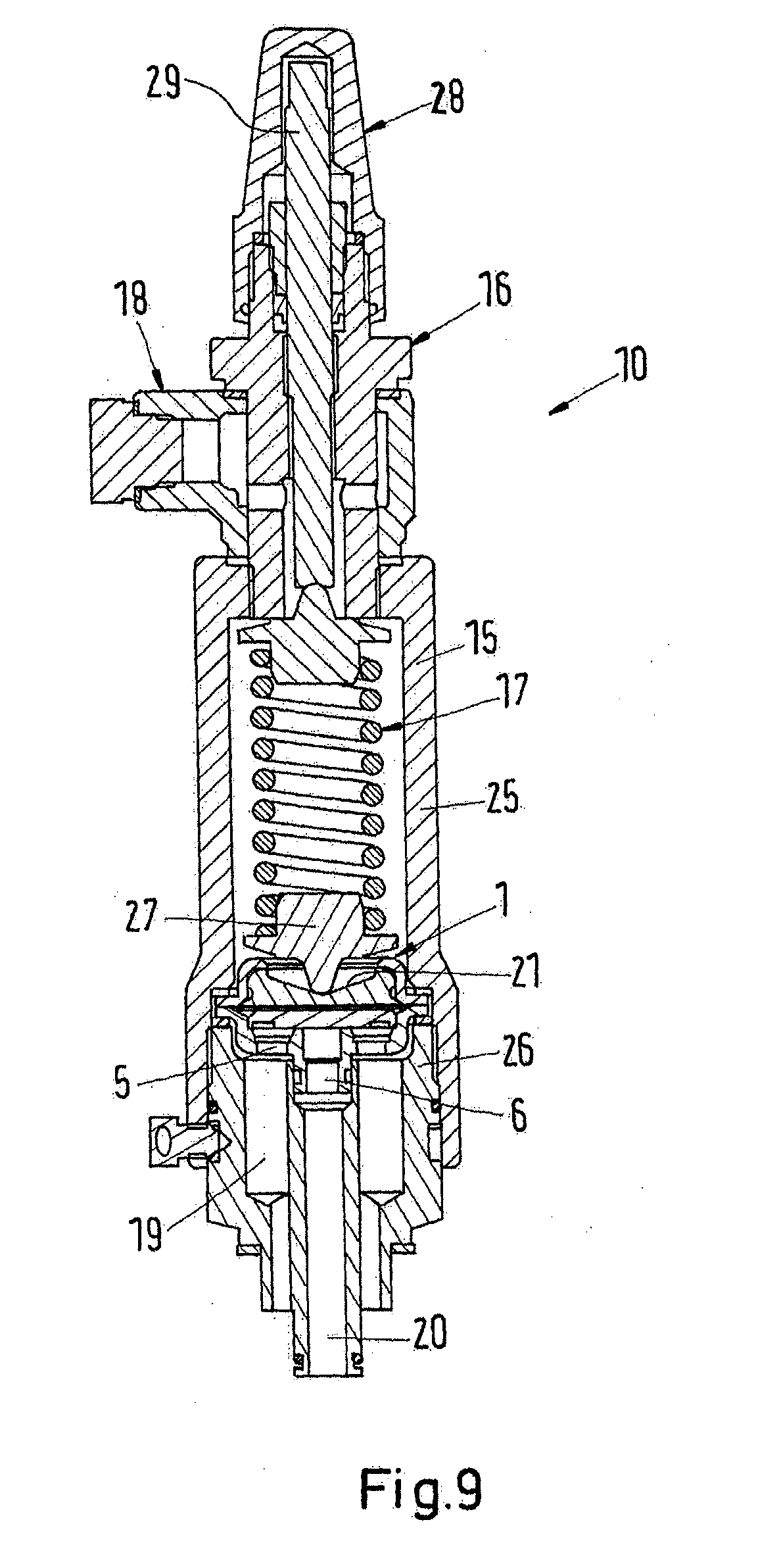
[0055] FIG. 9 shows a fifth embodiment according to the invention. Corresponding features to the previous embodiments are denoted with the same reference signs. This embodiment is mostly identical to the fourth embodiment except for an additional presetting means. The presetting mechanism 16 here in addition to a spring mechanism 17 with a presetting handle 29 also comprises a pressure port 18. The pressure port 18 allows to change the pressure in the pressure chamber 23 on the side of the diaphragm 2 opposite to the valve seat. Consequently, by increasing the pressure on the side of the diaphragm opposite to the valve seat the minimum pressure necessary on the side of the capsule inlet 5 to open the valve is increased. This embodiment is more flexible with respect to the fluids and pressures the valve 10 can be used with.
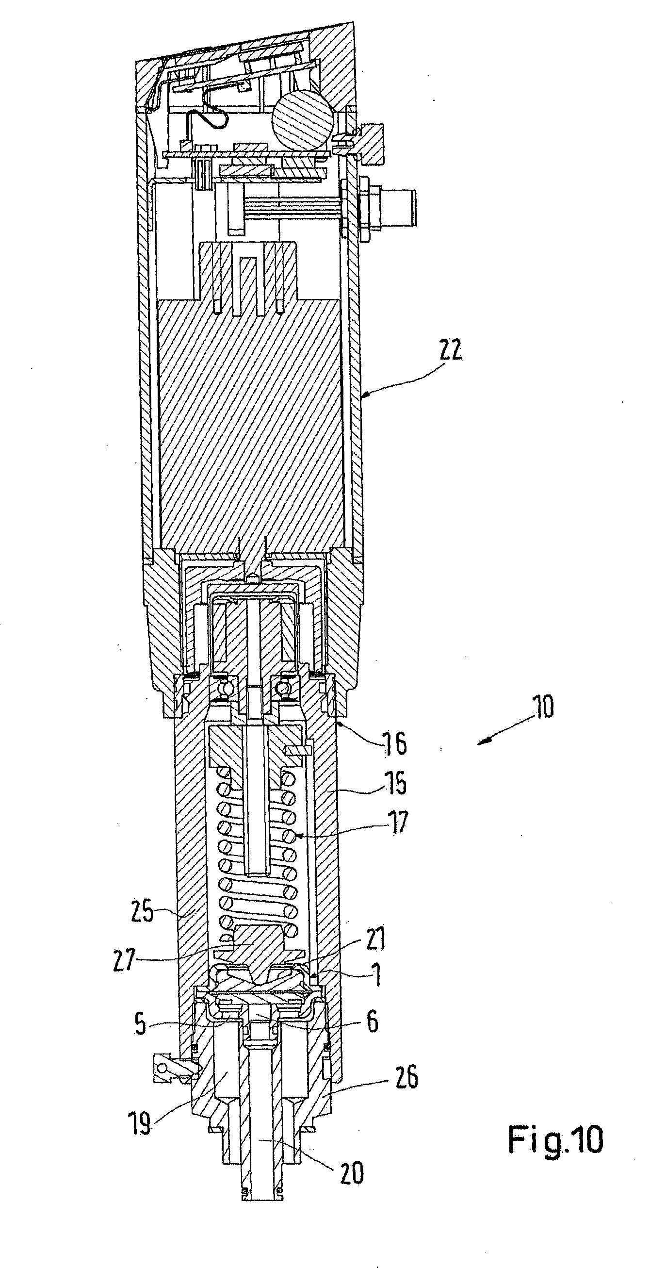
[0056] FIG. 10 shows a sixth embodiment according to the invention. Again corresponding features to the previous embodiments are denoted with the same reference signs. The sixth embodiment is similar to the fourth embodiment in that the presetting mechanism 16 comprises a spring mechanism 17. However, the presetting mechanism 17 here is controlled by a stepper motor 22. The stepper motor 22 can for example be controlled by an external control unit which allows to control the opening pressure differential of the valve during operation of the valve 10.
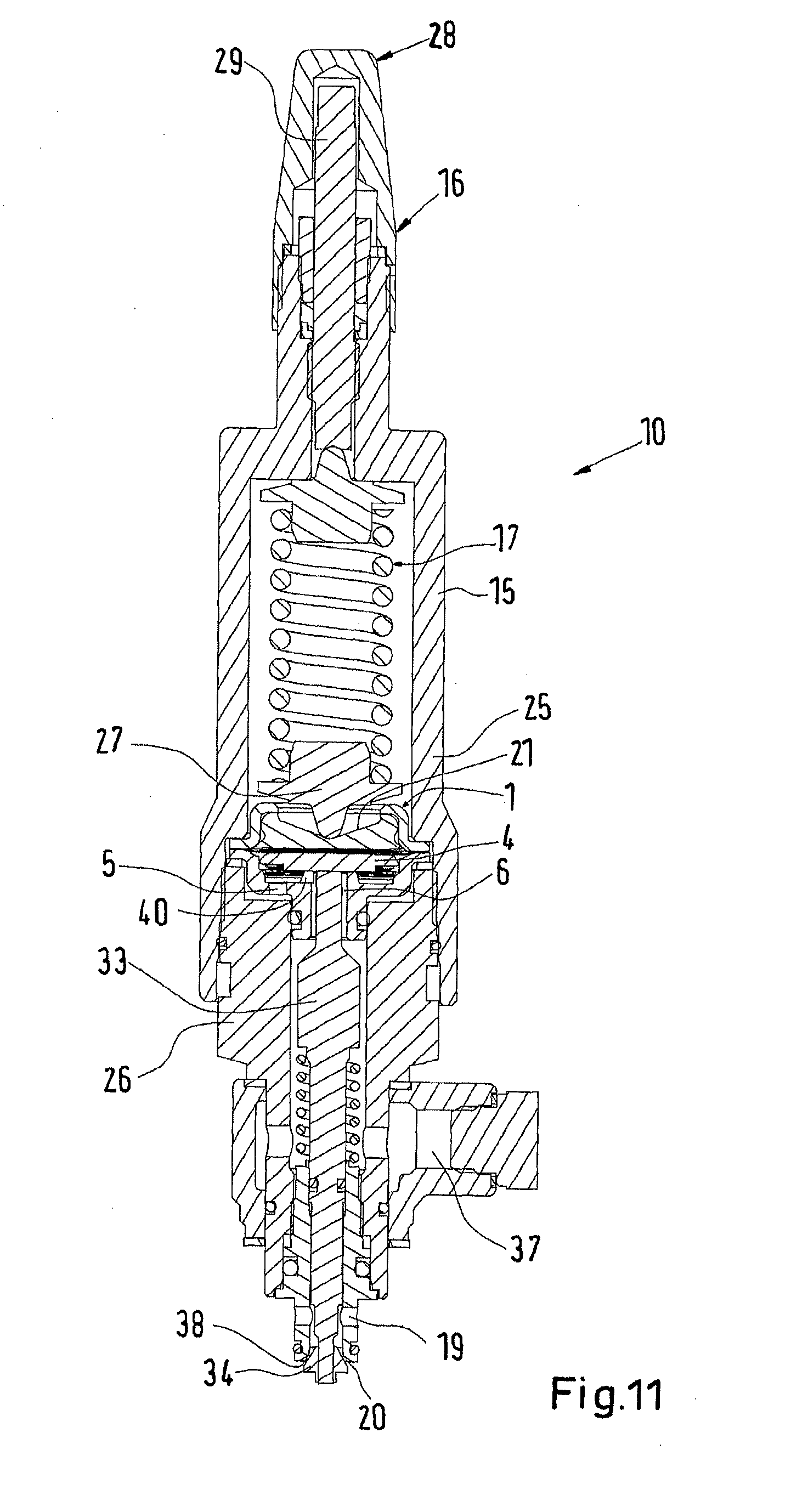
[0057] FIG. 11 shows a seventh embodiment according to the invention. In this embodiment of the valve 10 the capsule 1 serves to indirectly control the opening behavior of the pilot valve 10. The valve 10 in this embodiment comprises a pilot valve element 34 external to the capsule 1. The pilot valve element 34 is actuatable by a displacement of the valve element 4 in the capsule 1. The valve element 4 and the pilot valve element 34 are indirectly connected by a pin 33. One axial end of the pin 33 abuts the valve element 4. The opposite end of the pin 33 is connected to the pilot valve element 34. The pilot valve element 34 is axially displaceable towards or away from a pilot valve seat 38 external to the capsule 1. The capsule 1 is connected to a pressure port 37 which provides a reference pressure used to control the opening or closing of the valve 10. The presetting mechanism 16 here similarly to the embodiments according to FIGS. 8 and 9 comprises a spring mechanism 17.
[0058] The main flow path through the valve 10 does not lead through the capsule 1 in this embodiment. The capsule 1 serves to actuate and preset the valve 10 together with the presetting mechanism 16. The valve 10 according to FIG. 11 is to be used together with a main valve with a housing to which the valve inlet 19 and the valve outlet 20 connect.
[0059] This embodiment comprises a capsule 1 according to the embodiment of FIGS. 5 and 6. Consequently, a recess 40 is arranged in the valve seat 3 of the capsule 1. Thereby, substantially the same pressure may be present at the pressure port 37 and across the second surface 12 in the pressure chamber 24 irrespective of the position of the valve element 4 relative to the valve seat 3.
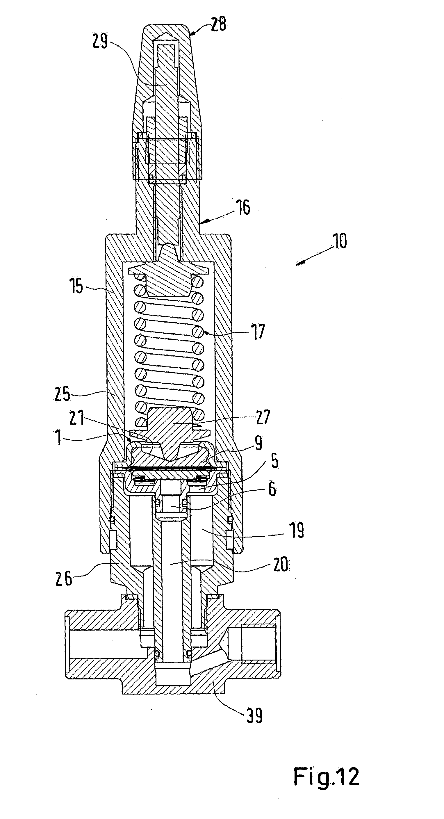
[0060] FIG. 12 shows an eighth embodiment according to the invention. Contrary to the previous embodiments the valve 10 here is a main valve, or in other words the capsule 1 is not part of a pilot valve. The valve 10 here is a regulating valve controlling the flow through the valve via the pressure difference over the diaphragm. When comparing to the embodiment according to FIG. 8 the valve housing 15 here comprises an additional housing part 39 which extends the valve inlet 19 and the valve outlet 20.
[0061] While the present disclosure has been illustrated and described with respect to a particular embodiment thereof, it should be appreciated by those of ordinary skill in the art that various modifications to this disclosure may be made without departing from the spirit and scope of the present disclosure.
* * * * *
D00000
D00001
D00002
D00003
D00004
D00005
D00006
D00007
D00008
D00009
D00010
D00011
D00012
XML
uspto.report is an independent third-party trademark research tool that is not affiliated, endorsed, or sponsored by the United States Patent and Trademark Office (USPTO) or any other governmental organization. The information provided by uspto.report is based on publicly available data at the time of writing and is intended for informational purposes only.
While we strive to provide accurate and up-to-date information, we do not guarantee the accuracy, completeness, reliability, or suitability of the information displayed on this site. The use of this site is at your own risk. Any reliance you place on such information is therefore strictly at your own risk.
All official trademark data, including owner information, should be verified by visiting the official USPTO website at www.uspto.gov. This site is not intended to replace professional legal advice and should not be used as a substitute for consulting with a legal professional who is knowledgeable about trademark law.