Air mover inlet interface and cover
Lofy; John David ; et al.
U.S. patent application number 15/999397 was filed with the patent office on 2019-01-03 for air mover inlet interface and cover. The applicant listed for this patent is Gentherm Incorporated. Invention is credited to Masahiko Inaba, John David Lofy.
| Application Number | 20190003491 15/999397 |
| Document ID | / |
| Family ID | 55079710 |
| Filed Date | 2019-01-03 |


| United States Patent Application | 20190003491 |
| Kind Code | A1 |
| Lofy; John David ; et al. | January 3, 2019 |
Air mover inlet interface and cover
Abstract
An air mover assembly comprising: (a) an impeller having an impeller outer diameter and a rotational axis; (b) a motor for driving the impeller; (c) an air mover housing that encloses at least a portion of the impeller and the motor, the air mover housing including: at least one air inlet that receives air when the impeller is rotating and at least one air outlet; and (d) an air mover inlet interface adjoining the at least one air inlet and including: (i) a height, (ii) a wall having a curvature along at least a portion of the height of the air mover inlet interface that extends outward in a direction of air flow, and (iii) an inner diameter; wherein the inner diameter is less than the impeller outer diameter.
| Inventors: | Lofy; John David; (Claremont, CA) ; Inaba; Masahiko; (Chino Hills, CA) | ||||||||||
| Applicant: |
|
||||||||||
|---|---|---|---|---|---|---|---|---|---|---|---|
| Family ID: | 55079710 | ||||||||||
| Appl. No.: | 15/999397 | ||||||||||
| Filed: | August 16, 2018 |
Related U.S. Patent Documents
| Application Number | Filing Date | Patent Number | ||
|---|---|---|---|---|
| 14797591 | Jul 13, 2015 | |||
| 15999397 | ||||
| 62031271 | Jul 31, 2014 | |||
| 62103662 | Jan 15, 2015 | |||
| Current U.S. Class: | 1/1 |
| Current CPC Class: | F04D 29/667 20130101; F04D 29/281 20130101; F04D 29/4213 20130101; F04D 25/08 20130101; F04D 29/703 20130101; F04D 29/4246 20130101; F04D 29/424 20130101; F04D 25/06 20130101 |
| International Class: | F04D 29/70 20060101 F04D029/70; F04D 29/66 20060101 F04D029/66; F04D 29/42 20060101 F04D029/42; F04D 29/28 20060101 F04D029/28; F04D 25/06 20060101 F04D025/06; F04D 25/08 20060101 F04D025/08 |
Claims
1-12. (canceled)
13. An air mover cover comprising: a grill portion adapted to allow movement of air while preventing objects of a predetermined size from passage; wherein the grill portion includes: (1) at least one first generally centrally disposed through hole opening having a first geometric shape, and a plurality of radially adjoining through hole openings having a second geometric shape different from the first geometric shape and radially adjoining the generally centrally disposed through hole opening; (2) a plurality of connection structures that have a center density in a central region of the grill portion and an adjacent density in regions surrounding the central region, where the center density is higher than the adjacent density when measured using a total length of the connection structure per unit area of each region; (3) at least one first generally centrally disposed through hole opening having a first area, and a plurality of radially adjoining through hole openings each having a second area that are each different than the first area; or (4) any combination of (1) through (3).
14. The air mover cover of claim 13, wherein the air mover cover includes a connection portion adapted to connect to an inlet or an outlet of an air mover housing.
15. The air mover cover of claim 14, wherein the connector portion includes a circumferential outwardly radiused wall.
16. The air mover cover of claim 13, wherein the grill portion has a plurality of second through hole openings radially adjoining the at least one first generally centrally disposed through hole opening, the plurality of second through hole openings having a second geometric shape.
17. The air mover cover of claim 13, wherein the at least one first generally centrally disposed through hole opening is pentagonal, and the plurality of second through hole openings are hexagonal.
18. The air mover cover of claim 13, wherein the grill portion is configured to have a contoured shape that is a dome shape having a height and a diameter and the ratio of the height to the diameter is from about 1:2 to about 1:100.
19. The air mover cover of claim 13, wherein the grill portion includes an outer density of connection structures that are located in an outer region that is radially disposed outside of the central region and the region surrounding the central region where the outer density is lower than both the center density and the adjacent density when measured using length of the connection structure per unit area.
20. The air mover cover of claim 13, wherein the cover is flat and the grill portion of the cover is flat.
21. The air mover cover of claim 13, wherein the grill portion has a generally contoured shape that is convex.
22. The air mover cover of claim 13, wherein a plurality of third through hole openings extend around the plurality of radially adjoining through hole openings and the third through hole openings are a partial shape.
23. The air mover cover of claim 13, wherein the second area of each of the plurality of radially adjoining through hole openings is greater than the first area of the at least one first generally centrally disposed through hole opening.
24. The air mover cover of claim 13, wherein the plurality of connection structures have a cross-sectional shape that is hexagonal.
25. The air mover cover of claim 13, wherein the plurality of connection structures have a cross-sectional shape that is circular.
26. The air mover cover of claim 13, wherein the air mover cover is integrally connected to an air mover inlet interface of an air mover assembly.
27. The air mover cover of claim 22, wherein the plurality of third through hole openings each have a third area that is less than the second area of each of the plurality of radially adjoining through hole openings and greater than the first area of the at least one first generally centrally disposed through hole opening.
28. The air mover cover of claim 22, wherein the plurality of third through hole openings are each a partial hexagonal shape.
29. The air mover cover of claim 18, wherein the ratio of the height to the diameter is from about 1:6 to about 1:10.
30. The air mover cover of claim 18, wherein the height of the grill portion is substantially equal to a thickness of the plurality of connection structures.
31. The air mover cover of claim 18, wherein the height of the grill portion is greater than a thickness of the plurality of connection structures,
32. The air mover cover of claim 13, wherein the at least one first generally centrally disposed through hole is a single generally centrally disposed through hole having a pentagonal shape.
Description
FIELD
[0001] The present teachings relate to an air mover with an improved inlet interface at an inlet, an outlet, or both that reduces noise and specifically aerodynamic noise created by the blower, and an improved cover for the inlet, the outlet, or both that prevents foreign objects from entering the air mover while reducing noise.
BACKGROUND
[0002] Air movers include a motor with a rotor and a stator. Generally, a shaft of the rotor extends through the stator and the rotor rotates about the stator. The rotor is in communication with an impeller that when rotated moves air. The motor and impeller are typically located within a housing having an inlet and an outlet so that air is pulled into the inlet and forced out the outlet by the impeller. Air as it enters and/or exits the housing generates aerodynamic noise that may be of sufficient decibels that the noise may be audible by a user, vibrations may be felt by a user, or both. Additionally, the inlets and outlets of the blower housing may include a cover that prevents foreign objects from entering the housing. The covers may restrict air flow, may exacerbate aerodynamic noise, or both created by the air mover. A majority of all air mover noise that is generated is due to aerodynamic noise created by the movement of air into, within, or out of the air mover. Examples of air movers and covers are disclosed in U.S. Pat. Nos. 2,001,522; 2,393,933; 4,531,890; 5,336,050; 6,003,950; and 6,547,519 and U.S. Patent Application Publication No. 2006/0171804; 2010/0098544; and 2012/0114512 the contents of which are expressly incorporated by reference herein in their entirety for all purposes.
[0003] What is needed is an air mover that includes an air mover interface that reduces the overall noise of the blower without unduly impeding the flow of air into the air mover. What is needed is an air mover interface that directs air to the impeller so that aerodynamic noise created by the air mover is reduced. What is needed is a cover that reduces noise of the blower without unduly impeding air movement into the blower. It would be desirable to have a cover that increases the amount of available area to feed the air mover inlet while maintaining an overall height of the air mover within a predetermined packaging space.
SUMMARY
[0004] The teachings herein surprisingly solve one or more of these problems by providing: an air mover assembly comprising: (a) an impeller having an impeller outer diameter and a rotational axis; (b) a motor for driving the impeller; (c) an air mover housing that encloses at least a portion of the impeller and the motor, the air mover housing including: at least one air inlet that receives air when the impeller is rotating and at least one air outlet; and (d) an air mover inlet interface adjoining the at least one air inlet and including: (i) a height, (ii) a wall having a curvature along at least a portion of the height of the air mover inlet interface that extends outward in a direction of air flow, and (iii) an inner diameter; wherein the inner diameter is less than the impeller outer diameter.
[0005] One possible embodiment of the present teachings includes: An air mover cover comprising: a grill portion adapted to allow movement of air while preventing objects of a predetermined size from passage; wherein the grill portion includes: (1) a generally contoured shape that is convex; (2) at least one first generally centrally disposed through hole opening having a first geometric shape, and a plurality of radially adjoining through hole openings having a second geometric shape different from the first geometric shape and radially adjoining the generally centrally disposed through hole opening; (3) a plurality of connection structures that have a center density in a central region of the grill portion and an adjacent density in regions surrounding the central region, where the center density is higher than the adjacent density when measured using a total length of the connection structure per unit area of each region; (4) at least one first generally centrally disposed through hole opening having a first area, and a plurality of radially adjoining through hole openings each having a second area that are each different than the first area; or (5) any combination of (1) through (4).
[0006] The present teachings surprisingly solve one of more of these problems by providing an air mover that includes an air mover interface that reduces the overall noise of the blower without unduly impeding the flow of air into the air mover. The present teachings provide an air mover interface that directs air to the impeller so that aerodynamic noise created by the air mover is reduced. The present teachings provide a cover that reduces noise of the blower without unduly impeding air movement into the blower. The present teachings provide a cover that increases the amount of available area to feed the air mover inlet while maintaining an overall height of the air mover within a predetermined packaging space.
BRIEF DESCRIPTION OF THE DRAWINGS
[0007] FIG. 1 illustrates a perspective view of an air mover;
[0008] FIG. 2 illustrates an exploded view of an air mover;
[0009] FIG. 3 illustrates a perspective cross-sectional view of the air mover of FIG. 1;
[0010] FIG. 4 illustrates cross-sectional view of the air mover of FIG. 1;
[0011] FIG. 5 illustrates a close-up view of the cross-section of the air mover of FIG. 4;
[0012] FIG. 6A illustrates an example of an air mover inlet interface having a rounded curvature;
[0013] FIG. 6B illustrates an example of an air mover inlet interface having a curvature with one flat portion;
[0014] FIG. 6C illustrates an example of an air mover inlet interface having an elliptical curvature;
[0015] FIG. 7 illustrates the increase in sound as flow is increased;
[0016] FIG. 8 illustrates a perspective view of an air mover including a cover;
[0017] FIG. 9 illustrates a top view of an air mover including a cover;
[0018] FIG. 10A illustrates a cross-sectional view of the air mover and cover of FIG. 8;
[0019] FIG. 10B illustrates a cross-sectional view of the air mover and cover when the cover is flat;
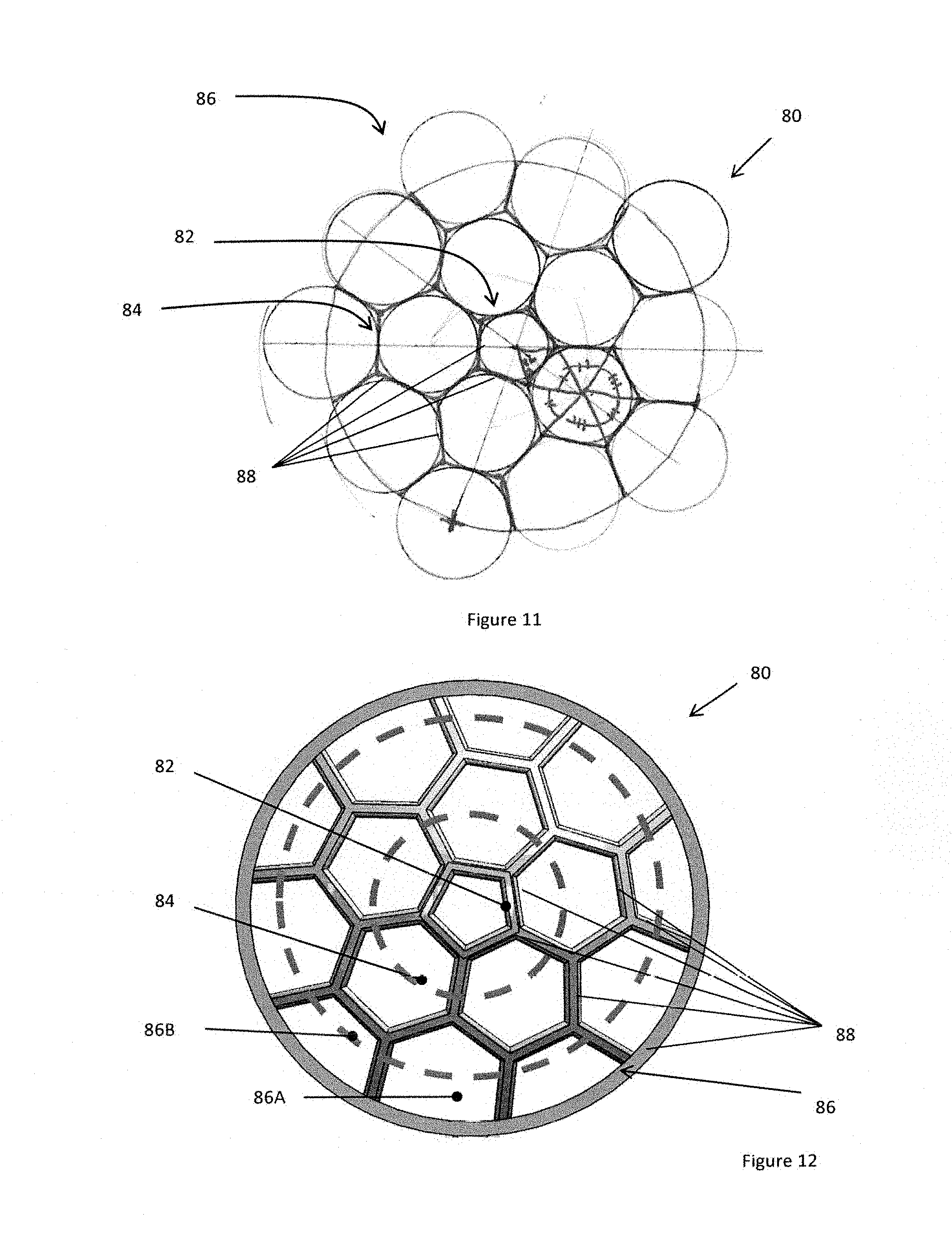
[0020] FIG. 11 illustrates geometries of the cover;
[0021] FIG. 12 illustrates a top view of the cover and the various through hole areas of the cover;
[0022] FIG. 13A illustrates a side view of a cover with a substantially flat profile dome;
[0023] FIG, 13B illustrates a side view of a cover with a low profile dome;
[0024] FIG. 13C illustrates a side view of a cover with a medium profile dome;
[0025] FIG. 13D illustrates a side view of a cover with a high profile;
[0026] FIG. 13E illustrates a side view of a flat cover that is integrally connected to the air air mover inlet interface;
[0027] FIG. 13F illustrates a side view of a flat cover only;
[0028] FIG. 13G illustrates a side view of a flat cover with connection structures having a circular-cross section and the flat cover being integrally connected to the air mover inlet interface;
[0029] FIG. 13H illustrates a side view of a flat cover only with connection structures having a circular cross-section; and
[0030] FIG. 14 illustrates a device for testing the sound created by the air mover.
DETAILED DESCRIPTION
[0031] The explanations and illustrations presented herein are intended to acquaint others skilled in the art with the invention, its principles, and its practical application. Those skilled in the art may adapt and apply the invention in its numerous forms, as may be best suited to the requirements of a particular use. Accordingly, the specific embodiments of the present invention as set forth are not intended as being exhaustive or limiting of the teachings. The scope of the teachings should, therefore, be determined not with reference to the above description, but should instead be determined with reference to the appended claims, along with the full scope of equivalents to which such claims are entitled. The disclosures of all articles and references, including patent applications and publications, are incorporated by reference for all purposes. Other combinations are also possible as will be gleaned from the following claims, which are also hereby incorporated by reference into this written description.
[0032] The present teachings claim priority to U.S. Provisional Patent Application No. 62/031,271, the contents of which are incorporated by reference herein in their entirety for all purposes. The present teachings may be used with any fan, blower, air mover, similar device that moves air, or a combination thereof. As discussed herein fan, blower, and air mover are used interchangeably and the use of the term fan is intended to encompass a blower, air mover, or any other device that moves a fluid such as air, or a combination thereof. The fan may function to move air from a first location to a second location to provide heat, remove heat, provide cooling, or a combination thereof. The fan may be a radial fan, an axial fan, or both. The fan may move air within a component. For example, the fan may move air into a cooling cabinet or a housing that includes equipment, electrical components, or both. The fan may be located in a vehicle. Preferably, the fan may be connected to a vehicle seat. The fan may be attached to, located under, or both the bun or cushion of a seat, in the back of a seat, or both. The fan may extend into a cushion of a vehicle seat so that the fan is located within the vehicle seat. The fan may be suspended during use (e.g., from an insert, from a seat cushion, from a seat frame, or a combination thereof). Preferably, the fan may be connected to a vehicle battery. The fan may be used in a vehicle to move a fluid through a vehicle seat. More preferably, the fan may be a low profile fan.
[0033] The present teachings are predicated upon providing a fan (i.e., a blower) that includes a housing, an impeller, a motor, and control instrumentation (e.g., circuitry). The housing may function to partially and/or fully enclose components of the fan to generate a pressure differential so that air is moved. The housing may enclose all of the functional components of the fan. The housing may connect the fan to channels, an air source, a thermoelectric device, may include a thermoelectric device, an insert, a hood, tubing, an open space, or a combination thereof. The housing may connect the fan to one or more devices so that the fan is retained within a device and/or system. For example, the fan may connect to a seat by the housing so that the fan may move air through the seat. The housing may include one or more inlets, one or more outlets, or both. For example, the housing may include two opposing outlets. The housing may be a one piece design. Preferably, the housing is a multi-piece design. For example, the housing may include a left piece and a right piece. The inlets, the outlets, or both may be partially or entirely formed in a left piece, a right piece, or both pieces. The inlets, outlets, or both may only be entirely formed when the left piece and right piece are connected together. For example, the left and right piece when combined may form a complete inlet. The multi-piece design may include an upper piece and a lower piece. The inlet, the outlets, or both may be partially or entirely located within one of the upper piece, the lower piece, or both. The multi-piece design may be connected around an impeller, a motor, or both so that all or a portion of the motor, the impeller, or both are located within the housing.
[0034] A motor may be connected within the system by a stator that may be connected to the housing so that the stator supports a rotor. The motor may function to rotate an impeller, move air, rotate a rotor, or both. The motor may function to rotate a rotor that moves an impeller. The motor may include a stator.
[0035] The stator may function to connect the rotor to the housing, to rotate the rotor, or both. The stator may rotate the rotor, the impeller, or both substantially about their axes. The stator may have one or more windings that move the rotor via the magnets of the rotor. The one or more windings when powered may create an electric field that moves the rotor and impeller so that air is moved.
[0036] The stator may be at least partially covered by a rotor. The rotor may function to rotate and move air, move an impeller, or both. The rotor may rotate about an axis (i.e., a rotational axis). The rotor may be located within and/or include one or more bearings so that the rotor has low friction rotation. The rotor may include an impeller that functions to move air. The rotor may include a cup and/or be connected to a cup so that a connection is formed with an Impeller.
[0037] The cup may function to substantially surround the stator, house a rotor, house one or more magnets, connect to a shaft, or a combination thereof. The cup may form a connection with the impeller so that the impeller is balanced, the impeller is positioned relative to the shaft, or both. The cup may be fixedly connected to a shaft. The cup may be permanently connected to the shaft. The cup may fixedly connect to one or more magnets so that the magnets are not directly connected to the impeller, the magnets may move the impeller around the stator, or both. The cup may be at least partially molded into the impeller, press fit into the impeller, or both.
[0038] The one or more magnets may function to move the rotor during operation of the fan. The one or more magnets may rotate about the stator when the windings are activated. The rotor may include a sufficient amount of magnets so that the rotor rotates, air is moved, or both. The one or more magnets may be positioned relative to the stator by the position of the cup, by the connection of the magnets to the cup, or both.
[0039] The impeller may receive all or a portion of a rotor. The impeller may include a hub. The hub may be wholly located within the housing. The hub may be sufficiently tall to house the motor within the housing. The hub may extend past the housing, out of the housing, or both. The hub may be free of a portion that extends out of the inlet. The hub may be about two-thirds the total height of the impeller or more, about three-quarters the total height of the impeller or more, or even the same height as the total height of the impeller or more. The hub may be about two-thirds the total height of the impeller or less, about half the total height of the impeller or less, or a quarter the total height of the impeller or less. The impeller may push air, pull air, or both. The impeller may be made of any material so that the impeller moves air. Preferably, the impeller is made of plastic or a light-weight material. The impeller may be made of a molded material, an injection molded material, or both. The impeller may be made of metal. The impeller may be large enough so that the impeller moves a sufficient amount of air to heat and/or cool an occupant, a user, a location of interest, or a combination thereof. The impeller may be sufficiently small so that the rotor fits within a component and preferably a vehicle component. Preferably, the impeller may be formed by injection molding and/or overmolding. The impeller may be molded around a cup, a shaft, or both of the rotor. For example, the hub of the impeller may be molded around a cup so that the hub houses at least a portion of the rotor. The hub may be part of a base of the impeller.
[0040] The base of the impeller may function to provide a support surface for vanes, provide a connection point for vanes, radially extend from a hub, or a combination thereof. The base may form a bottom most wall of the impeller. The impeller, the base of the impeller, or both include a diameter and the diameter of the impeller, the base, or both may be equal. The base may support one or more and preferably a plurality of vanes. The base may form an outer most diameter. The base may be made of molded plastic, metal, a polymer, a flowable material, or a combination thereof. The base may be integrally formed, integrally connected, or both to a plurality of vanes.
[0041] The vanes may function to move air when the impeller rotates about a rotational axis. The vanes may move air in one or more directions. The vanes may be unidirectional vanes so that air is moved in a single direction. Preferably, the vanes pull air in through an inlet and radially move the air out through an outlet. However, the vanes may axially move air from an inlet to an outlet. The vanes may be located about a circumference of the impeller. Each of the vanes may be parallel to the adjacent vanes. The one or more vanes include an upper edge, a lower edge, an outer edge, and an inner edge (i.e., edges). The edges may include one or more linear segments, one or more curved segments, one or more parallel edges, one or more edges that extend at an angle relative to another edge. The edges may be such that the vanes are generally square, generally rectangular, generally a rhombus, generally a trapezium, have an angled portion that slopes away from an opposing edge, or a combination thereof. The upper edges of the plurality of vanes may generally terminate along a plane so that the upper edges are all generally the same height. The lower edges may all generally terminate at the base. The outer edge may be located at an outside of the diameter of the impeller. The inner edge may be located towards a center of the impeller relative to the outer edge. The inner edge, the upper edge, or both may have a sloped portion. The vanes may include a contoured surface. The contoured surface may function to move air in a primary direction. The contoured surface of the vanes may radially move air. The contoured surface may extend in a direction of rotation or opposite a direction of rotation. The vanes, the impeller, or both may include an outer diameter (e.g., a largest diameter of the impeller). The outer diameter may be varied depending upon a predetermined amount of fluid to be moved. The outer diameter may be increased to increase a volume of fluid to be moved. The outer diameter may be located at the outer edge of the vanes, the outer edge of the base, or both. The outer diameter may extend substantially to the walls of the housing. The outer diameter of the impeller may be larger than the largest dimension of the inlet of the housing (e.g., diameter).
[0042] The inlet may function to allow air to enter the housing, the air mover assembly, or both when the impeller rotates. The inlet may function to provide direct access to the impeller and vanes during operation. The inlet may be located above the impeller, above the motor, along an axis of rotation, or a combination thereof. The inlet may include an air mover inlet interface.
[0043] The air mover inlet interface may be a surface that directs air into the inlet. The air mover inlet interface may function to reduce the speed of fluids (e.g., air) extending into the inlet. The air mover inlet interface may function to reduce the turbulence of fluids entering the inlet. The air mover inlet interface may project outward from the housing. The air mover inlet interface may project axially away from the housing. The air mover inlet interface may gradually open as the air mover inlet interface axially extends into the housing, towards the impeller, or both. The air mover inlet interface may include an inner circumferential edge, an outer circumferential edge, or both.
[0044] The inner circumferential edge may function to guide air into the air mover inlet interface, form a low friction entry point for fluids (e.g., air), or both. The inner circumferential edge may be an outermost edge of the air mover inlet interface. The inner circumferential edge may be a terminal edge of the air mover inlet interface. The inner circumferential edge may form an inner inlet diameter, have an inner inlet diameter, or both. The inner inlet diameter may be the smallest diameter of the inlet. The inner circumferential edge may be connected to a radiused surface, a curvature, or both.
[0045] The radiused surface, curvature, or both may function to gradually open up so that space within the inlet gradually increases. The radiused surface may function to connect an inner circumferential edge to an outer circumferential edge. The radiused surface may include a single curve, a constant curvature, an arc, one or more arcuate sections, one or more curves, one or more linear segments, one or more curves with a radial curve, one or more curves with an oval curve, or a combination thereof. The radiused surface may extend outward and reduce the size of the inlet opening. The radiused surface may bell out so that a volume within the air mover inlet interface increases as the radiused surface extends axially towards the impeller. The radiused surface includes a height. The height of the radiused surface may be sufficiently large so that fluid is channeled towards the impeller, the fluid is all moved substantially along the rotational axis as the fluid contacts the impeller, or a combination of both. The height of the radiused surface may be 2 mm or more, 3 mm or more, 4 mm or more, 5 mm or more, 6 mm or more, or even 10 mm or more. The height of the radiused surface may be about 30 mm or less, 25 mm or less, 20 mm or less, or even about 15 mm or less. The radiused surface may extend at a radius that is sufficiently large that the radius reduces the aerodynamic noise generated by the flow of a fluid into the inlet of the air mover. The radiused surface may have a radius of about 2 mm or more, 3 mm or more, 4 mm or more, 5 mm or more, 6 mm or more (e.g., R6), or even 7 mm or more. The radiused surface may have a radius of about 30 mm or less, about 25 mm or less, about 20 mm or less, or about 15 mm or less. The height of the radiused surface may be inversely proportional to the volume of sound created by the air mover. For example, the longer the radiused surface the less sound the air mover may create (however, the diameter of the inlet may directly affect the volume of sound created by the air mover). The radiused surface may extend inward and terminate at an outer circumferential edge.
[0046] The outer circumferential edge may function to create an outer diameter of the air mover inlet interface. The outer circumferential edge may function to create a connection surface, connection point, or both with the housing. The outer circumferential edge may be a location on the air mover inlet interface where the radiused surface terminates. The outer circumferential edge may include an inlet outer diameter. The inlet outer diameter may have a size that is less than the size of the impeller (e.g., the diameter of the inlet outer diameter may be less than the outer diameter of the impeller). The outer circumferential edge may extend into the inlet of the housing. The outer circumferential edge may terminate at a top of the housing. The outer circumferential edge may guide fluid toward the impeller, into the housing, or both. The outer circumferential edge may be substantially free of contact with the fluid as the fluid moves into the housing.
[0047] The fluid as it enters the inlet through the air mover inlet interface may be directed towards the impeller. The fluid as it moves may function to create a constant flow, a laminar flow, a flow that is free of turbulence, or a combination thereof so that the aerodynamic noise is not created by the flow of the fluid. The movement of the fluid may be generally along the axial direction of the impeller as the fluid travels within the air mover inlet interface and then the fluid movement may extend radially outward into contact with the impeller. Movement of the fluid may be varied based upon use of a cover over the inlet.
[0048] The cover may function to prevent foreign objects from entering the blower, from user limbs and/or digits from entering the blower, or both. The cover may function to provide screening of fluids entering the blower. The cover may function to limit interference with fluid flow while preventing access to the impeller. The cover may be dome shaped, hemispherical, rounded, arcuate, flat, have a flat portion, have a rounded portion, have an elevated portion that gradually raises above the rest of the cover, or a combination thereof. Preferably, the cover is of a flat profile (e.g., 80 percent or more of the cover extends within a single plane). A highest point on the cover (e.g., a peak) may be located substantially in the center of the cover or may be offset from center. The height of the cover may be equal throughout the entire area of the cover. The height of the cover may be substantially equal to the thickness of the connecting structures. The height of the cover at the center may be substantially equal to the height of the cover at an outer radius, an outermost edge, or both. The height (i.e., tallest point) of the cover may have a ratio relative to the cross-sectional length (e.g., diameter) of the cover. The ratio of height to cross-sectional length may be about 1:2 or more, 1:4 or more, or about 1:6 or more (i.e., about 1:6.6). The ratio of height to cross-sectional length may be about 1:100 or less, 1:50 or less, 1:30 or less, about 1:15 or less, or about 1:10 or less. The cover may be free of a domed shape. The cover, the grill portion of the cover, or both may be configured to allow for a constant stream of fluid into the air mover, to be non-restrictive to air flow, minimize restriction, or a combination thereof. The cover may include a series of through holes located between a series of connection structures. The through holes may be randomly disposed within the area of the cover (e.g., the grill portion). The through holes may be uniformly disposed within the area of the cover (e.g., grill portion). The through holes may connect together to form a grill portion that air travels through to reach the impeller. The grill portion may include one or more groups of holes, one or more series of holes, one or more radially extending holes, or a combination thereof. Preferably, the grill portion includes at least one first generally centrally disposed through hole opening (i.e., one or more first through holes).
[0049] The one or more first through holes may function to create a structure in a central portion of the grill portion. The one or more first through holes may function to provide structure to an outermost portion of the grill portion, to provide strength to the grill portion, restrict entry of foreign objects, or a combination thereof. The one or more first though holes may have a plurality of connection structures that have a density. The one or more first through holes may be located in a central region, along the axis of rotation, or a combination of both. The one or more first through holes may be any shape so that one or more adjoining through holes may be radially disposed about the one or more first through holes. The one or more first through holes may have an area of about 25 mm.sup.2 or more, preferably about 35 mm.sup.2 or more, or more preferably about 45 mm.sup.2 or more (e.g., about 51 mm.sup.2). The one or more first through holes may be about 110 mm.sup.2 or less, about 100 mm.sup.2 or less, about 75 mm.sup.2 or less, or about 60 mm.sup.2 or less. The one or more first through holes may be a round, oval, square, rectangle, diamond, pentagon, hexagon, octagon, heptagon, or a combination thereof. Preferably, the one or more first through holes is a single pentagonal through hole located in the center of the grill portion. The one or more first through holes may all be the same size. The one or more first though holes may be different sizes. The one or more first through holes may be the same size as the through holes that are radially disposed about the first through holes.
[0050] One or more and preferably a plurality of radially adjoining through hole openings (i.e., second through holes) may be radially disposed about the first through hole. The second through holes may function to provide structure to the grill portion, form a curve, form a dome, provide strength to the grill, or a combination thereof. The second through holes may function to increase in cross-sectional length, area, or both relative to the cross-sectional length, area, or both of the first through hole openings so that air may pass through the through hole openings. The second through holes may have a plurality of connection structures. The connection structures of the second through holes may have a density that is less than that of the first though holes. The density as discussed herein is the density of the connection structures per unity area unless otherwise stated. The second through holes may include more open area then the first though holes so that the density of the second through holes is less than the first though holes. The density of the connection structures of the second through holes may be decrease as the second through holes extend radially outward. The density may be measured by measuring the total length of the connection structures per unit area. For example, the total length of the connection structures may be 50 mm and the area of all of the second through holes may be 625 mm.sup.2 (e.g., 1 mm/12.5 mm.sup.2) and the total length of the connection structures of the first through holes may be about 15 mm and the area of all of the first though holes may be about 80 mm.sup.2 (e.g., 1 mm/5 mm.sup.2). The second through hole openings may be larger than the first through hole openings but smaller than the third through hole openings. The one or more second through holes may have an area of about 70 mm.sup.2 or more, preferably about 90 mm.sup.2 or more, or more preferably about 110 mm.sup.2 or more (e.g., about 115 mm.sup.2). The one or more second through holes may be about 200 mm.sup.2 or less, about 175 mm.sup.2 or less, about 150 mm.sup.2 or less, or about 130 mm.sup.2 or less. The second through hole openings may all be the same size, may all be different sizes, may be a combination of two or more sizes, or a combination thereof. The one or more second through hole openings may be any of the shapes discussed herein for the first through hole openings. Preferably, the second through hole openings are smaller than third through hole openings.
[0051] The one or more and preferably a plurality of radially adjoining through hole openings (i.e., third through holes) may be radially disposed about the plurality of second through holes. The one or more third through holes may perform any of the functions of the second through holes, the first through holes, or both and vice versa as discussed herein. The third through holes may function to create a dome shape, to prevent foreign objects from entering the blower, or both. The one or more third through hole openings may be any of the shapes discussed herein for the first through hole openings, the second through hole openings, or both. The third through holes may have a density. The density of the third through holes may be the length of the connection structures per unit area. The density of the through holes may be less than that of the second through holes. The density of each of the third through holes may be less than each of the second through holes, each of the first through holes, or both. Similarly, the density of the total group of third through holes may be less than that of the total group of the second through holes and the first through holes. The density of the group of through holes may be solely based upon the amount of connection structures forming each through hole. Preferably, however, the density is based upon the amount of connection structures per unit area. The one or more third through holes may have an area of about 100 mm.sup.2 or more, preferably about 125 mm.sup.2 or more, or more preferably about 140 mm.sup.2 or more (e.g., about 155 mm.sup.2). The one or more third through holes may be about 300 mm.sup.2 or less, about 250 mm.sup.2 or less, about 200 mm.sup.2 or less, or about 175 mm.sup.2 or less. The one or more third through holes may be a partial hexagonal shape and thus the area may be less than a full hexagonal shape. The area of the partial third through holes may have an alternating area. For example, one third through hole opening may be a partial so that the area is close to a complete area and an adjoining third through hole opening may be about half of a total through hole opening. The third through hole openings may have a partial area of about 175 mm.sup.2 or less, about 150 mm.sup.2 or less, about 120 mm.sup.2 or less, about 100 mm.sup.2 or less, or even about 75 mm.sup.2 or less. The third through hole openings may have a partial area of about 40 mm.sup.2 or more, 50 mm.sup.2 or more, or 60 mm.sup.2 or more.
[0052] The grill portion may include two groups of radially disposed through holes or more, three groups of radially disposed through holes or more, four groups of radially disposed through holes or more, or even five groups of radially disposed through holes or more. The teachings of the second and third through holes are incorporated herein for the fourth, fifth, sixth, or more groups of through holes. Each of groups two, three, four, or more may decrease in density, increase in area, or both so that fluid flow is not unduly impeded by the connection structures.
[0053] The one or more and preferably a plurality of connection structures may function to protect the impeller, prevent foreign objects from entering the impeller, or both. The one or more connection structures may resist pressure, force, or both from damaging the blower, the impeller, or both. The one or more connection structures may be the material that forms the grill portion. The one or more connection structures may be features that are interconnected to form the grill, each of the series of through holes, or both. The one or more connection structures may be ribs that radially extend outward and interconnect with adjacent connection structures. The one or more connection structures may be generally arcuate, have linear segments, connected to adjacent linear segments and form an angle between the adjacent linear segments, or a combination thereof. The one or more connection structures may have any cross-sectional shape that prevents foreign objects from entering the inlet, resists crushing of the cover, or both. The one or more connection structures may have a cross-sectional shape that is hexagonal, circular, square, pentagonal, triangular, oval, diamond, symmetrical, non-symmetrical, or a combination thereof. The length of the connection structure in each of the first through hole opening, second through hole opening, third through hole opening, etc. . . . may increase in length as the through hole openings are measured radially outward. The connection structures of the first through hole openings may have a length of about 3 mm or more, 4 mm or more, 5 mm or more. The connection structures of the first through hole openings may have a length of about 7 mm or less, about 6 mm or less. The connection structures of the second through hole openings may have a length of about 4 mm or more, about 5 mm or more, about 6 mm or more (i.e., 6.6 mm). The connection structures of the second through hole openings may have a length of about 9 mm or less, about 8 mm or less, or about 7 mm or less. The connection structures of the third through hole openings may have a length of about 5 mm or more, about 6 mm or more, about 7 mm or more (i.e., 7.6 mm). The connection structures of the third through hole openings may have a length of about 10 mm or less, about 9 mm or less, or about 8 mm or less.
[0054] The sound created by the air mover may be tested. The testing assembly may be located within a structure that functions to remove all ambient sounds. The testing assembly may include a sound meter. The sound meter may be a digital sound meter. The air mover outlet may be connected directly to a flow meter thus the static pressure or system resistance may be substantially zero. The air mover outlet may be connected to a diffuser box that may be adjusted to create a predetermined static pressure or system resistance. The static pressure or system resistance used during measurement may be calculated based upon the resistance of the system the air mover is intended to be used in conjunction with. Preferably, the system resistance, the static pressure or both against the outlet of the air mover assembly is about 50 percent. The system resistance may be calculated using a system resistance curve for each given fan as the system resistance may vary based upon the size of the air mover assembly. A flow meter may be used to test the volume of flow being produced by each air mover assembly as the covers, the air mover inlet interface, or both are varied and the sound generated by each are tested. The decibels created by the air mover assembly of the teachings herein may be about 67 or less, about 66.5 or less, about 66 or less, preferably about 65.75 or less, more preferably about 66.5 or less, or even about 66.25 or less when the sound meter is placed at a distance of 200 mm and a static pressure (system resistance) of 50 percent is applied to the air mover.
EXAMPLES
[0055] The following test may be used to determine the amount of sound created by the air mover. The air mover assembly is placed in a sound proof room. A sound meter is placed 200 mm from the inlet of the air mover. The outlets of the air mover may be restricted to create a static pressure (e.g., system resistance) on the air mover of 50 percent. One or both of the outlets are connected to a diffuser box that includes a flow meter. A flow meter is in communication with the diffuser box that measures the flow of air exiting the air mover assembly.
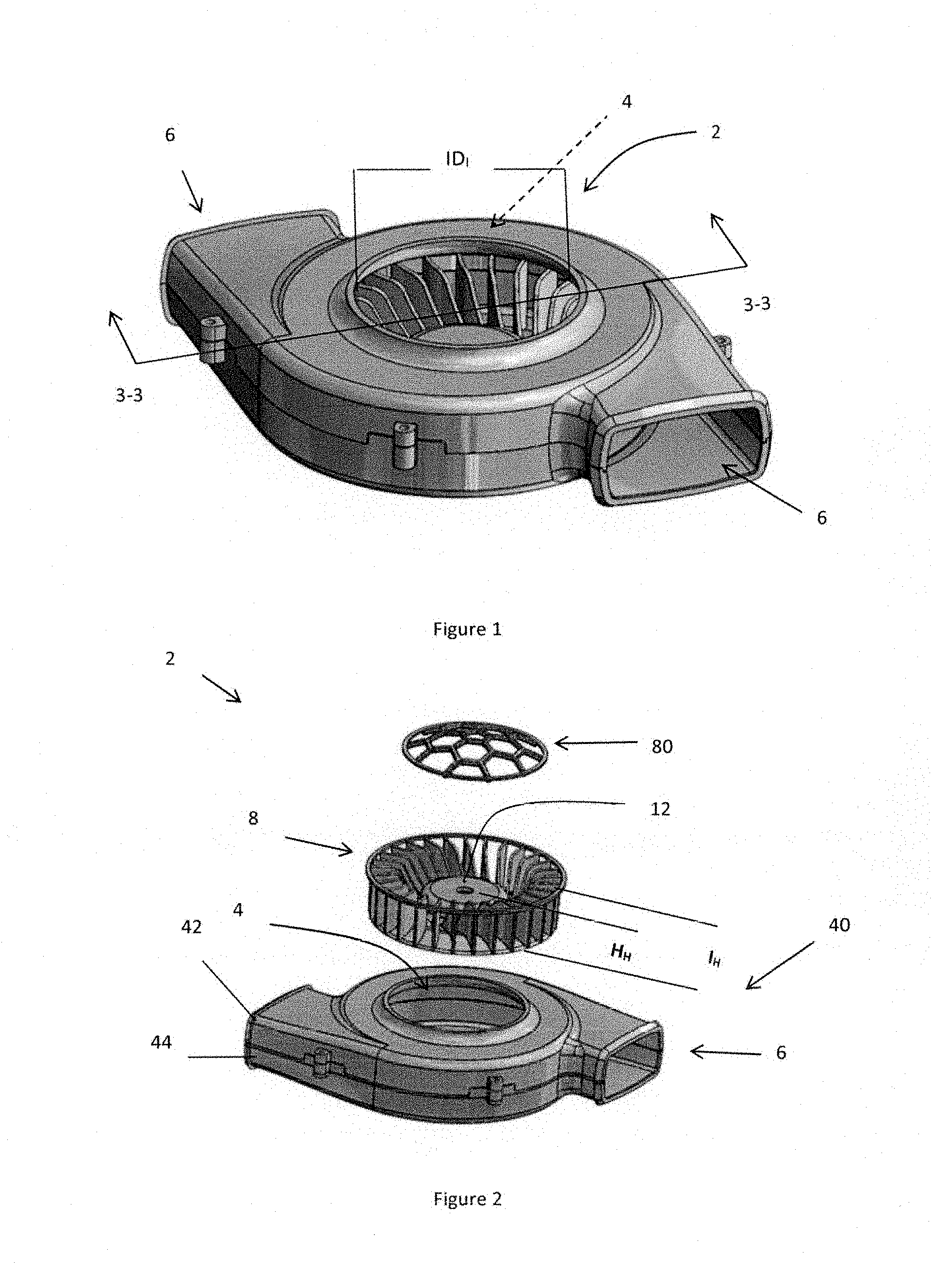
[0056] FIG. 1 illustrates a perspective view of an air mover assembly 2. The air move assembly 2 includes an inlet 4 having an inner diameter (ID.sub.I) and a pair of opposing outlets 6.
[0057] FIG. 2 illustrates an exploded view of an air mover assembly 2. The air move assembly 2 includes a housing 40 with an upper piece 42 and a lower piece 44. The upper piece 42 includes an inlet 4 and a pair or outlets 6 are formed between the upper piece 42 and the lower piece 44. The impeller 8 is removed from the housing 40 and a cover 80 that extends over the inlet 4 is shown. The impeller 8 includes a total height (I.sub.H) and the hub 12 has a total height of (H.sub.H).
[0058] FIG. 3 illustrates a cross-sectional (perspective) view of the air mover assembly 2 of FIG. 1 cut along line 3-3. The air mover assembly 2 includes a housing 40 that houses an impeller 8. The impeller 8 includes a base 28 with a hub 12 and a plurality of vanes 14 extending therefrom. Each of the vanes 14 include an upper edge 16, a lower edge 18, an outer edge 20, and an inner edge 22. As illustrated, the inner edge 22 has a sloped portion 24 and a contoured surface 26. The housing 40 as illustrated includes an air mover inlet interface 60. The air mover inlet interface 60 has an inner circumferential edge 62 and an outer circumferential edge 64 connected by a radiused surface 66 (e.g., a curvature).
[0059] FIG. 4 illustrates a cross-sectional (plan) view of the air mover assembly 2 of FIG. 1 cut along line 3-3. The housing 40 includes an impeller 8 that has a hub 12 which receives a portion of the motor 30. An axis of rotation 10 extends through the center of the impeller 8, motor 30, and an inlet 4 of the housing 40. The housing 40 has an air mover inlet interface 60 that extends axially away from the impeller 8. The air mover inlet interface 60 has a radiused surface 66 that extends between an inlet inner diameter (ID.sub.I) and an inlet outer diameter (ID.sub.O). The impeller 8 includes an outer diameter (D.sub.O) that is larger than the inlet inner diameter (ID.sub.I) and an inlet outer diameter (ID.sub.O).
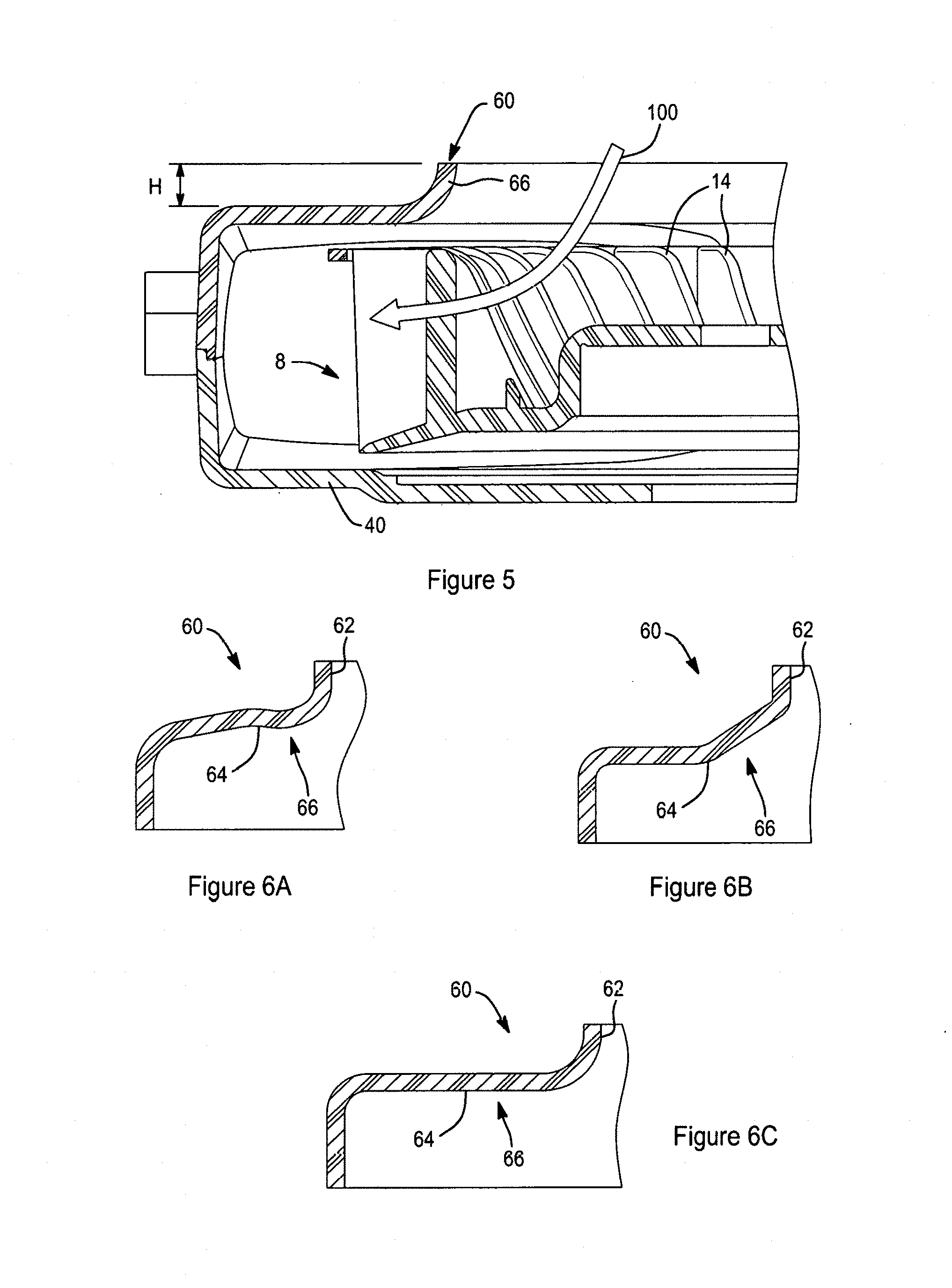
[0060] FIG. 5 illustrates a close-up view of the housing 40 of FIG. 4. An impeller 8 with a plurality of vanes 18 is located within the housing 40. The impeller 8 moves air into the inlet and the air mover inlet interface 60 directs the flow of air in the direction 100 so that the air gradually turns as the air moves into the housing 40. The air mover inlet interface 60 has a radiused surface 66 that extends axially away from the impeller 8 and has a height (H).
[0061] FIGS. 6A-6C illustrates a close up example of air mover inlet interface 60 that may be used with the housing (not shown) or the cover (not shown). FIG. 6A illustrates the air mover inlet interface 60 having a radiused surface 66 that gradually extends between an inner circumferential edge 62 and an outer circumferential edge 64. The radiused surface 66 has a generally circular radius.
[0062] FIG. 6B illustrates the air mover inlet interface 60 having a radiused surface 66 that includes a linear segment with multiple curves between the inner circumferential edge 62 and an outer circumferential edge 64.
[0063] FIG. 6C illustrates the air mover inlet interface having an extended radiused surface 66 that extends between an inner circumferential edge 62 and an outer circumferential edge 64. The radiused surface 66 has an elliptical radius.
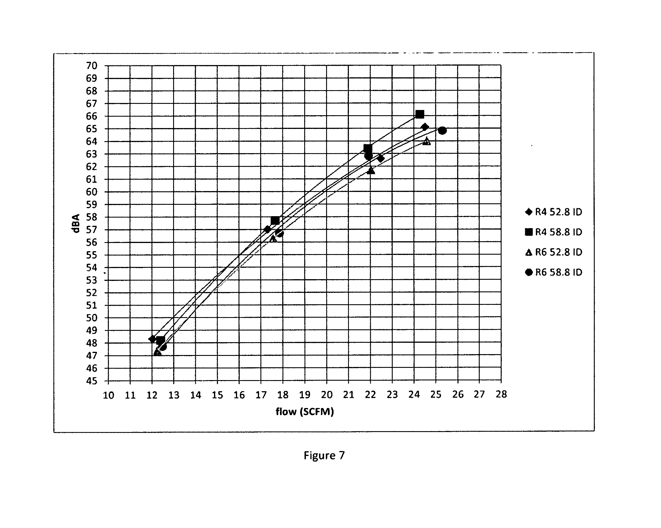
[0064] FIG. 7 chart plotting airflow versus noise. As illustrated, for all 4 blowers as the amount of flow increases so does noise associated with the blower. As illustrated in the legend the first blower has a radius of 4 mm with an inner inlet diameter of 52.8 mm, the second blower has a radius of 4 mm with an inner inlet diameter of 58.8 mm, the third blower has a radius of 6 mm with an inner inlet diameter of 52.8 mm, and the fourth blower has a radius of 6 mm with an inner inlet diameter of 58.8 mm. As illustrated, as the radius size of the air mover inlet interface is increased the noise created by the blower is decreased relative to an air mover with an air mover inlet interface with a smaller radius. As illustrated, as the inlet inner diameter of the fans is increased the noise increases.
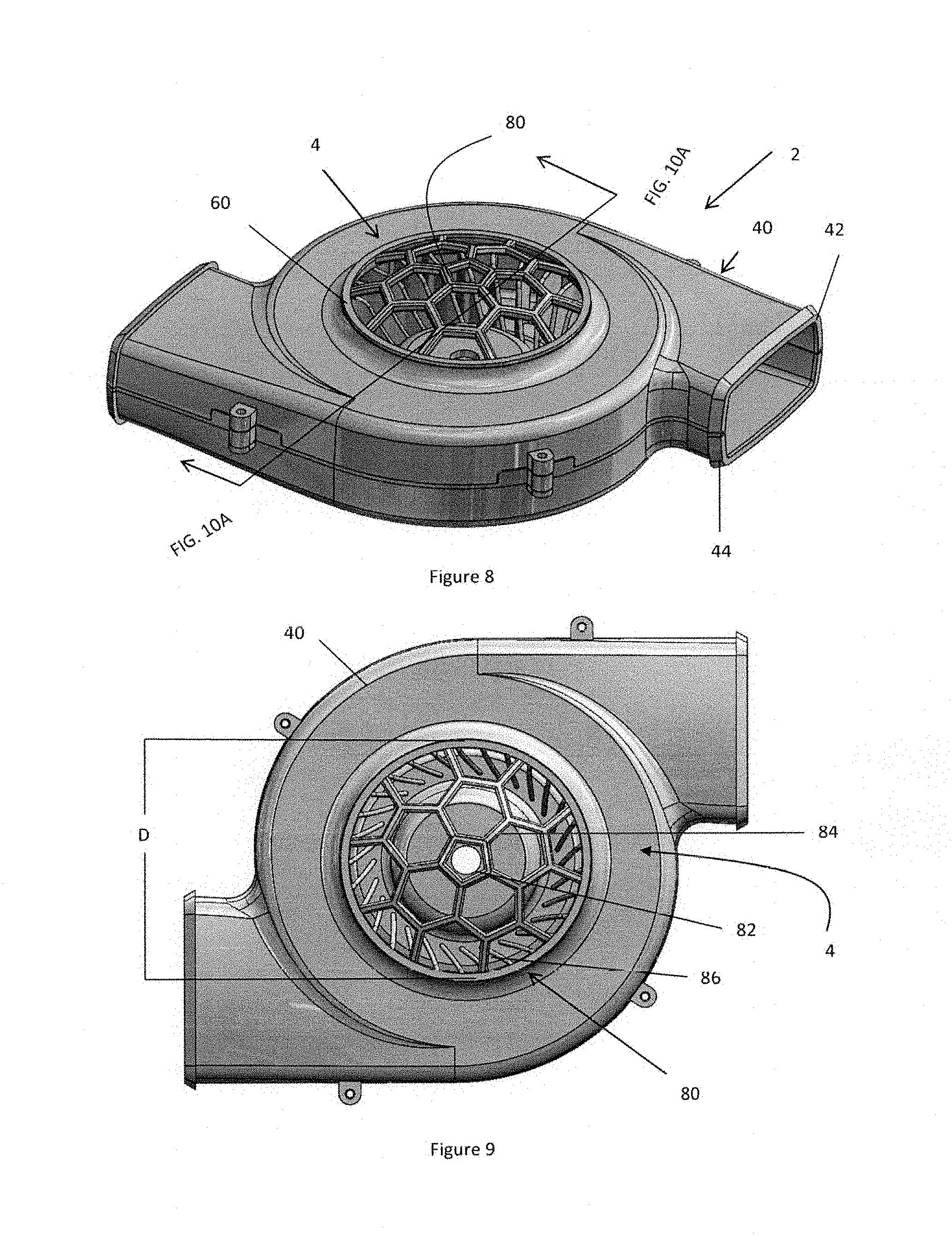
[0065] FIG. 8 illustrates a perspective view of an air mover assembly 2. The air mover 2 includes a housing 40 having an upper piece 42 and a lower piece 44. The upper piece 42 as illustrated has an inlet 4 that includes a cover 80 (which may be integral with the housing or removable). An air mover inlet interface 60 extends between the cover 80 and the housing 40.
[0066] FIG. 9 illustrates a top view of the housing 40 with a cover 80 over the inlet 4. The cover 80 includes a first generally centrally disposed through hole opening 82 located in a central region of the inlet 4. The cover 80 includes a plurality of radially adjoining through hole openings (e.g., second set of openings) 84 radially disposed in a region radially outside of the central region. The cover includes a second plurality of radially adjoining through hole openings (e.g., third set of openings) 86 radially disposed in a region radially outside of the openings adjoining the first generally centrally disposed through hole opening 82. The cover 80 includes a diameter (D) that is generally the same size as the inlet 4.
[0067] FIG. 10A illustrates a cross-sectional view along lines 10A-10A of FIG. 8. As the impeller 8 is turned by the motor 30 air is moved in the direction 100 through the cover 80 and the hole design in the domed cover 80 reduces aerodynamic noise. The domed cover 80 has a height (H).
[0068] FIG. 10B illustrates a cross-sectional view of an air mover assembly 2 having a flat cover 80. As impeller 8 is turned by the motor 30 air is moved in the direction 100 through the cover 80 and the hole design in the cover 80 reduces aerodynamic noise. The cover 80 has a height (H').
[0069] FIG. 11 illustrates a cover 80 configuration where the density of connection structures 88 decreases as the connection structures 88 are measured radially outward of the center. As illustrated, the first generally centrally disposed through hole opening 82 has the greatest density of connection structures 88 per unit area. A group of radially adjoining through hole openings 84 extend around the first through hole opening 82 and have a lower density of connection structures 88. A second group of radially adjoining through hole openings 86 are radially outward of the group of through hole openings 84 and have a lower density of connection structures relative to the first through hole 82 and the group 84. The decreases in density of the connection structures 88 is demonstrated by the increase in hole size as the holes extend radially outward.
[0070] FIG. 12 illustrates the cover 80 with the first through hole opening 82 having a first area (e.g., about 51 mm.sup.2) being located in the center and be pentagonal in shape. A group of second through hole openings 84 having a second area (e.g., about 115 mm.sup.2) extend around the first through hole opening 82 along the first dashed circle. A third group of through hole openings 86 extend around the second group of through hole openings 84 and the first though hole opening 82. Each of the through hole openings is formed by a plurality of connection structures 88 which are interconnected. The second through hole openings 84 and the third through hole openings 86 are hexagons. The third through hole openings 86 have a first area 86A (e.g., about 128 mm.sup.2) and a second area 86B (e.g., about 75 mm.sup.2) that are different.
[0071] FIG. 13A illustrates a side view of a cover 80 that has a dome height (H.sub.1). The height (H.sub.1) is substantially flat.
[0072] FIG. 13B illustrates a side view of a cover 80 that has a dome height (H.sub.2). The height (H.sub.2) is low profile but extends higher than the height (H.sub.1).
[0073] FIG. 13C illustrates a side view of a cover 80 that has a dome height (H.sub.3). The height (H.sub.3) is a medium profile but extends higher than the height (H.sub.2).
[0074] FIG. 13D illustrates a side view of a cover 80 that has a dome height (H.sub.4). The height (H.sub.4) is low profile but extends higher than the height (H.sub.3).
[0075] FIG. 13E illustrates a perspective view of a flat cover 80 that has connection structures 88 with a hexagonal cross-sectional shape and the cover 80 being integrally connected to an air mover inlet interface 60.
[0076] FIG. 13F illustrates a perspective view of a flat cover 80 that has connection structures 88 with a hexagonal cross-sectional shape.
[0077] FIG. 13G illustrates a perspective view of a flat cover 80 that has connection structures 88 with a circular cross-sectional shape and the cover 80 being integrally connected to an air mover inlet interface 60.
[0078] FIG. 13H illustrates a perspective view of a flat cover 80 that has connection structures 88 with a circular cross-sectional shape.
[0079] FIG. 14 illustrates an example of a testing device 120. The testing device 120 is located in a sound proof room 130. The testing device 120 includes a digital sound meter 132 that is located a distance (D.sub.S) above the inlet 4 of an air mover assembly 2. An outlet of the air mover assembly 2 is connected to a diffuser box 134. The diffuser box 134 replicated back pressure created by connecting the air mover assembly 2 to a seating system (not shown). The diffuser box includes a flow meter 136 that measures the flow of air generated by the air mover assembly 2.
[0080] Any numerical values recited herein include all values from the lower value to the upper value in increments of one unit provided that there is a separation of at least 2 units between any lower value and any higher value. As an example, if it is stated that the amount of a component or a value of a process variable such as, for example, temperature, pressure, time and the like is, for example, from 1 to 90, preferably from 20 to 80, more preferably from 30 to 70, it is intended that values such as 15 to 85, 22 to 68, 43 to 51, 30 to 32 etc. are expressly enumerated in this specification. For values which are less than one, one unit is considered to be 0.0001, 0.001, 0.01 or 0.1 as appropriate. These are only examples of what is specifically intended and all possible combinations of numerical values between the lowest value and the highest value enumerated are to be considered to be expressly stated in this application in a similar manner.
[0081] The disclosures of all articles and references, including patent applications and publications, are incorporated by reference for all purposes. The term "consisting essentially of" to describe a combination shall include the elements, ingredients, components or steps identified, and such other elements ingredients, components or steps that do not materially affect the basic and novel characteristics of the combination. The use of the terms "comprising" or "including" to describe combinations of elements, ingredients, components or steps herein also contemplates embodiments that consist essentially of the elements, ingredients, components or steps. By use of the term "may" herein, it is intended that any described attributes that "may" be included are optional.
[0082] Plural elements, ingredients, components or steps can be provided by a single integrated element, ingredient, component or step. Alternatively, a single integrated element, ingredient, component or step might be divided into separate plural elements, ingredients, components or steps. The disclosure of "a" or "one" to describe an element, ingredient, component or step is not intended to foreclose additional elements, ingredients, components or steps.
* * * * *
D00000
D00001
D00002
D00003
D00004
D00005
D00006
D00007
D00008
D00009
D00010
XML
uspto.report is an independent third-party trademark research tool that is not affiliated, endorsed, or sponsored by the United States Patent and Trademark Office (USPTO) or any other governmental organization. The information provided by uspto.report is based on publicly available data at the time of writing and is intended for informational purposes only.
While we strive to provide accurate and up-to-date information, we do not guarantee the accuracy, completeness, reliability, or suitability of the information displayed on this site. The use of this site is at your own risk. Any reliance you place on such information is therefore strictly at your own risk.
All official trademark data, including owner information, should be verified by visiting the official USPTO website at www.uspto.gov. This site is not intended to replace professional legal advice and should not be used as a substitute for consulting with a legal professional who is knowledgeable about trademark law.