Systems And Methods For Hydrate Management
Kanstad; Stig Kaare ; et al.
U.S. patent application number 15/639059 was filed with the patent office on 2019-01-03 for systems and methods for hydrate management. The applicant listed for this patent is OneSubsea IP UK Limited. Invention is credited to Bjoern Aalstad, Stig Kaare Kanstad.
| Application Number | 20190003293 15/639059 |
| Document ID | / |
| Family ID | 62837685 |
| Filed Date | 2019-01-03 |

View All Diagrams
| United States Patent Application | 20190003293 |
| Kind Code | A1 |
| Kanstad; Stig Kaare ; et al. | January 3, 2019 |
SYSTEMS AND METHODS FOR HYDRATE MANAGEMENT
Abstract
An apparatus includes a first flow line, a second flow line and a seabed-disposed pump station. The first and second flow lines extend to a sea surface platform. The pump station to, in response to a shut down of a production flow in the first flow line, operate a pump of the station to transfer liquid from the first flow line to the second flow line to reduce a liquid column in the first flow line and push liquid in the second flow line to the sea surface platform for removal; and open a bypass valve for the pump to allow a liquid column in the second flow line to decrease to reduce a pressure in the second flow line during a period in which the pump station is shut down. The pump station may also be operated to communicate a pig through flow lines, and during a time interval in which the production is shut down, the pump station may be operated in a bypass mode to prevent hydrate formation in a subsea flow line.
| Inventors: | Kanstad; Stig Kaare; (Bergen, NO) ; Aalstad; Bjoern; (Bergen, NO) | ||||||||||
| Applicant: |
|
||||||||||
|---|---|---|---|---|---|---|---|---|---|---|---|
| Family ID: | 62837685 | ||||||||||
| Appl. No.: | 15/639059 | ||||||||||
| Filed: | June 30, 2017 |
| Current U.S. Class: | 1/1 |
| Current CPC Class: | E21B 41/0007 20130101; E21B 43/255 20130101; E21B 43/168 20130101; E21B 43/101 20130101; E21B 43/013 20130101; E21B 43/01 20130101; E21B 37/06 20130101 |
| International Class: | E21B 43/25 20060101 E21B043/25; E21B 43/013 20060101 E21B043/013; E21B 43/16 20060101 E21B043/16; E21B 43/10 20060101 E21B043/10 |
Claims
1. A method comprising: shutting down production from a subsea well, comprising reducing a pressure in a first flow line; wherein reducing the pressure in the first flow line comprises: operating a seabed disposed pump to draw down liquid followed by gas to reduce a liquid level in a second flow line extending from a surface platform and push liquid in the first flow line to the surface platform; and removing liquid from the first flow line at the surface platform.
2. The method of claim 1, further comprising: operating the seabed disposed pump to communicate a production flow from the subsea well through the first flow line.
3. The method of claim 1, wherein: removing the liquid from the first flow line comprises using a separator disposed on the surface platform; and the first flow line extends to the separator.
4. The method of claim 3, wherein reducing the pressure in the first flow line further comprises: operating a pump bypass valve to bypass the seabed disposed pump to decrease a liquid column height of the liquid in the first flow line.
5. The method of claim 3, wherein reducing the pressure further comprises flaring gas present in the first flow line.
6. The method of claim 1, wherein reducing the pressure in the first flow line further comprises: stopping the seabed disposed pump and allowing liquid in the first flow line to flow through a pump bypass valve and through a local recirculation path.
7. The method of claim 1, wherein shutting down production comprises shutting down production flow through the first flow line and continuing a production flow through another flow line while production flow through the first flow line is shut down.
8. An apparatus comprising: a first flow line to extend to a sea surface platform; a second flow line to extend to the sea surface platform; and a seabed-disposed pump station to, in response to a shut down of a production flow in the first flow line: operate a pump of the seabed-disposed pump station to flow a liquid followed by a gas in the first flow line and to transfer the liquid from the first flow line to the second flow line to reduce a liquid column in the first flow line and push liquid in the second flow line to the sea surface platform for removal; and open a bypass valve for the pump to allow a liquid column in the second flow line to decrease to reduce a pressure in the second flow line.
9. The apparatus of claim 8, further comprising: a wellhead valve to connect the first flow line to the second flow line to form a path to allow operation of the pump to transfer liquid from the first flow line to the second flow line.
10. The apparatus of claim 8, wherein the seabed-disposed pump station closes the bypass valve, resumes operation of the pump and subsequently reopens the bypass valve to reduce the pressure in the second flow line during the period in which the seabed-disposed pump station is shut down.
11. The apparatus of claim 8, wherein the pump operates to pump production fluid from a well, through the second flow line, and to the sea surface platform.
12-25. (canceled)
26. A system, comprising: a controller; and a subsea pump communicatively coupled to the controller, wherein the subsea pump is configured to couple with first and second flow lines extending to a surface platform, the controller is configured to operate the subsea pump to drive a fluid flow from the surface platform to the subsea pump through the first flow line and from the subsea pump to the surface platform through the second flow line in response to a shutdown of a production flow, wherein the fluid flow in the first flow line comprises a liquid followed by a gas to reduce a first liquid level in the first flow line.
27. The system of claim 26, wherein the controller is configured to operate the subsea pump to reduce the first liquid level in the first flow line to reduce pressure and hydrate formation in the first flow line.
28. The system of claim 27, wherein the controller is configured to control removal of liquid in the second flow line at the surface platform to reduce a second liquid level, pressure, and hydrate formation in the second flow line.
29. The system of claim 28, comprising a liquid gas separator coupled to the second flow line.
30. The system of claim 26, comprising a bypass valve configured to bypass the subsea pump to reduce a second liquid level in the second flow line.
31. The system of claim 30, wherein the subsea pump is coupled to a local recirculation path.
32. The system of claim 31, wherein the local recirculation path comprises a loop between the subsea pump and a wellhead.
33. The system of claim 26, comprising a valve disposed between the first and second flow lines.
34. The system of claim 33, wherein the valve is disposed at a wellhead.
35. The system of claim 26, comprising at least a portion of the first flow line and at least a portion of the second flow line.
36. A method, comprising: identifying a shutdown condition of a production flow; and controlling a subsea pump to drive a fluid flow from a surface platform to the subsea pump through a first flow line and from the subsea pump to the surface platform through a second flow line in response to the shutdown condition, wherein the fluid flow in the first flow line comprises a liquid followed by a gas to reduce a first liquid level in the first flow line.
37. The method of claim 36, wherein controlling the subsea pump comprises reducing the first liquid level in the first flow line to reduce pressure and hydrate formation in the first flow line.
38. The method of claim 37, comprising controlling removal of liquid in the second flow line at the surface platform to reduce a second liquid level, pressure, and hydrate formation in the second flow line.
39. The method of claim 36, comprising controlling a bypass valve to bypass the subsea pump and provide fluid flow along a local recirculation path between the subsea pump and a wellhead.
Description
BACKGROUND
[0001] Natural gas hydrates are crystalline solids that form when water and natural gas combine in high pressure and low temperature environments. The formation of hydrates may occur in oil and natural gas wells, pipelines, pumping systems, production systems, and other industrial applications. In some instances, hydrate formations may result in the precipitation of ice-like hydrate plugs, which may reduce or block flow in fluid lines, including production lines.
SUMMARY
[0002] In accordance with an example implementation, a technique includes shutting down production from a subsea well, including reducing a pressure in a first flow line. Reducing the pressure in the first flow line includes operating a seabed disposed pump to draw down liquid in a second flow line extending from a surface platform and push liquid in the first flow line to the surface platform; and removing liquid from the first flow line at the surface platform.
[0003] In accordance with another example implementation, an apparatus includes a first flow line, a second flow line and a seabed-disposed pump station. The first and second flow lines extend to a sea surface platform. The pump station to, in response to a shut down of production flow in the first flow line, operate a pump of the station to transfer liquid from the first flow line to the second flow line to reduce a liquid column in the first flow line and push liquid in the second flow line to the sea surface platform for removal; and open a bypass valve for the pump to allow a liquid column in the second flow line to decrease to reduce a pressure in the second flow line.
[0004] In accordance with another example implementation, a technique includes operating a seabed-disposed pump station to communicate a production flow from a subsea well; operating the seabed-disposed pump station to draw a pig through a first flow line, where the first flow line extends between the pump station and a sea surface platform; and operating the pump station to push the pig through a second flow line to the platform.
[0005] In accordance with another example implementation, an apparatus includes a seabed-disposed pump station and a pig detector. The pump station to communicate a production flow from a subsea well. The pump station includes a pump and is adapted to be placed in a first state to allow operation of the pump to draw a pig through a first flow line, where the first flow line extending between the pump station and a sea surface platform; in response to the pig detector detecting the pig, be placed in a second state to allow the pig to be pushed through a path from an inlet of the pump to an outlet of the pump; and resume operation of the pump to push the pig through a second flow line to the platform.
[0006] In accordance with yet another example implementation, a technique includes shutting down production from a subsea well; and during a time interval in which the production is shut down, operating a subsea production pump in a bypass mode to remove hydrate formations in a subsea flow line.
[0007] Advantages and other features will become apparent from the following drawings, description and claims.
BRIEF DESCRIPTION OF THE DRAWINGS
[0008] FIGS. 1 and 3 are schematic diagrams of subsea production systems according to example implementations.
[0009] FIGS. 2A and 2B are flow diagrams depicting techniques to inhibit hydrate formation in a flow line according to example implementations.
[0010] FIGS. 4 and 6 are schematic diagrams of seabed-disposed pump stations according to example implementations.
[0011] FIG. 5 is a schematic diagram illustrating a state of the pump station of FIG. 4 during a pigging operation according to an example implementation.
[0012] FIG. 7 is a schematic diagram illustrating a state of the pump station of FIG. 6 in which a service fluid is used to push a pig from a position downstream of a pump of the pump station to a position upstream of the pump according to an example implementation.
[0013] FIGS. 8, 9 and 10 are flow diagrams depicting seabed-disposed pump station-based pigging operations according to example implementations.
[0014] FIG. 11 is a schematic diagram of a pump station according to a further example implementation.
[0015] FIG. 12 is a flow diagram depicting a technique remove hydrate formations from a flow line according to an example implementation.
DETAILED DESCRIPTION
[0016] In the drawings and description that follow, like parts are typically marked throughout the specification and drawings with the same reference numerals. The drawing figures are not necessarily to scale. Certain features of the disclosed implementations may be shown exaggerated in scale or in somewhat schematic form and some details of conventional elements may not be shown in the interest of clarity and conciseness. The present disclosure is susceptible to implementations of different forms. Specific implementations are described in detail and are shown in the drawings, with the understanding that the present disclosure is to be considered an exemplification of the principles of the disclosure, and is not intended to limit the disclosure to that illustrated and described herein. It is to be fully recognized that the different teachings of the implementations discussed below may be employed separately or in any suitable combination to produce desired results.
[0017] Unless otherwise specified, in the following discussion and in the claims, the terms "including" and "comprising" are used in an open-ended fashion, and thus should be interpreted to mean "including, but not limited to." Any use of any form of the terms "connect," "engage," "couple," "attach," or any other term describing an interaction between elements is not meant to limit the interaction to direct interaction between the elements and may also include indirect interaction between the elements described. The various characteristics mentioned above, as well as other features and characteristics described in more detail below, will be readily apparent to those skilled in the art upon reading the following detailed description of the implementations, and by referring to the accompanying drawings.
[0018] A flow line of a subsea production system may occasionally undergo a period of time in which no flow is communicated through the flow line. For example, the flow line may be a production flow line, and production through the flow line may temporarily be shut down due to equipment failure, routine maintenance, well intervention, and so forth. During this shutdown interval, the conditions for hydrates to form in the flow line may be favorable, and as such, hydrate formations in the flow line potentially restrict or block flow through the flow line when the flow is to resume.
[0019] In accordance with example implementations that are described herein, a seabed-disposed pump station is operated in a manner to create a relatively low pressure inside a flow line to prepare the flow line for shut down. The low pressure, in turn, inhibits hydrate formation inside the flow line. Moreover, in accordance with example implementations, the seabed-disposed pump station may be used to assist in pigging operations; and in yet further example implementations, the pump station may have a recirculation mode of operation in which thermal energy from the pump station is used in a local recirculation path (a local recirculation path between the pump station and the well head and/or a local recirculation path inside the pump station, as examples) to remove hydrates from a partially blocked flow line.
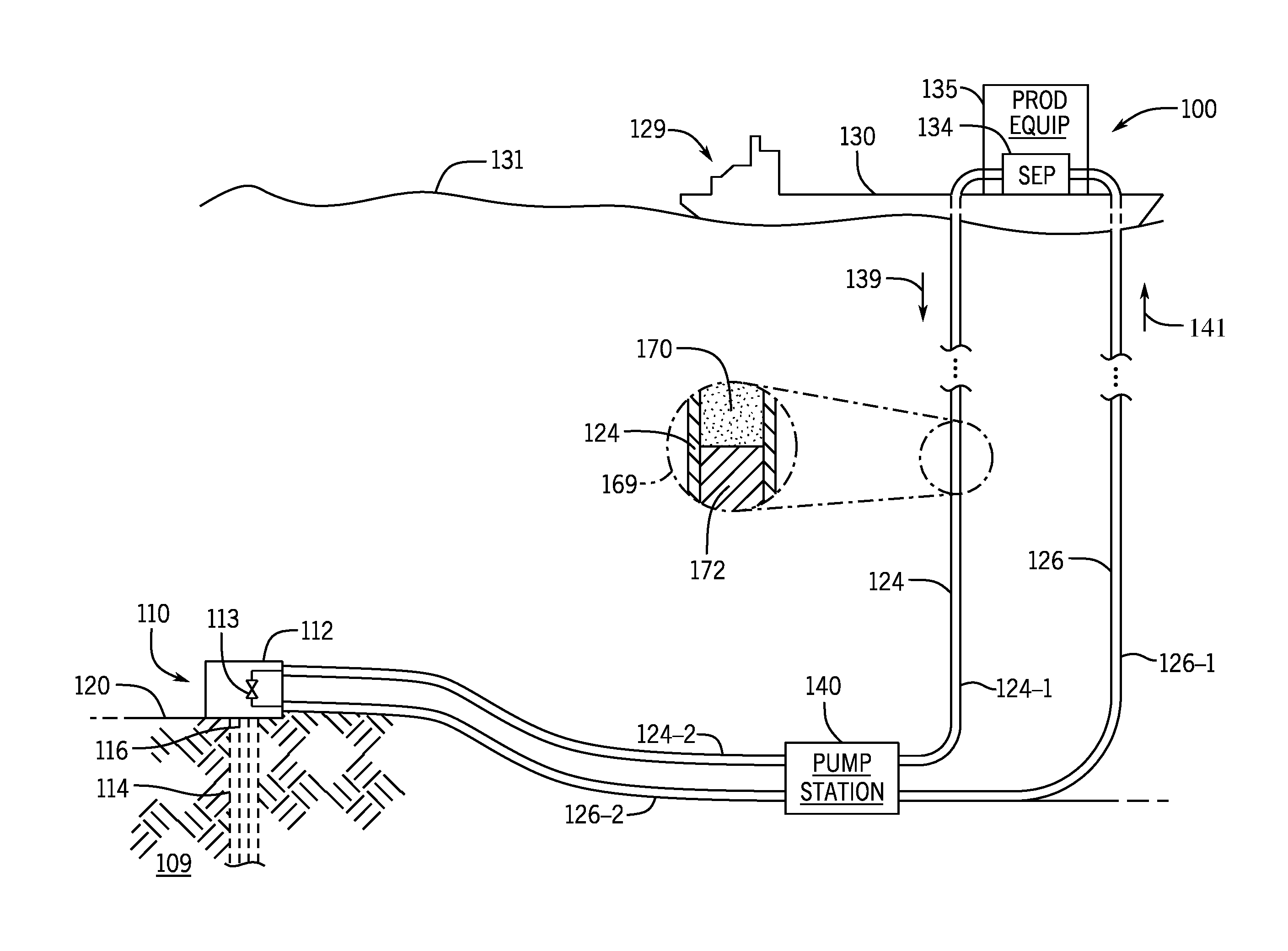
[0020] More specifically, referring to FIG. 1, in accordance with example implementations, a subsea production system 100 includes a well 110 that extends into a sea floor, or seabed 120, for purposes of producing hydrocarbon-based well fluid from one or multiple geologic formations 109. In this regard, as depicted in FIG. 1, the well 110 may include a wellbore 114, one or multiple production strings 116 that extend into the wellbore 114, and so forth. Moreover, as depicted in FIG. 1, the well 110 may include a wellhead 112, which may include various valves, a manifold and potentially other controls for purposes of controlling fluid flow to and from the well 110. In this manner, the wellhead 112 may be connected to a flow line, which communicates produced well fluid and extends to production equipment 135 that is located on a platform 129 (a platform that includes a surface vessel 130 for the example implementation of FIG. 1) at the sea surface 131.
[0021] As depicted in FIG. 1, the subsea production system 100 may include flow lines, which extend from the seabed 120 to the surface platform 129, such as example flow lines 124 and 126. The flow lines 124 and 126 may be used for various purposes, such as, for example, communicating produced well fluid from the well 110 to the surface platform 129 and communicating chemicals, service fluids, and to the well 110 from the sea surface platform 129 and so forth. Moreover, different flow lines may be used for production at different times.
[0022] In accordance with example implementations, flow lines of the subsea production system 100, such as the flow lines 124 and 126, may be disposed inside a riser (not shown) that extends from the sea surface platform 129 to the wellhead 112.
[0023] For the example implementation depicted in FIG. 1, the sea surface platform 129 is formed by a surface vessel 130. However, the platform 129 may take on other forms, in accordance with further example implementations. As examples, the sea surface platform 129 may be a floating production system, such as a floating, storage and offloading (FSO) system or a floating, production, storage and offloading (FPSO) system. In accordance with further example implementations, the sea surface platform 129 may be a drilling vessel, a semi-submersible floating platform, a tension leg platform that is connected by mooring cables to the sea bed 120, a gravity-based platform that is anchored directly to the sea bed 120 by a rigid anchor, and so forth.
[0024] In accordance with example implementations, a pump station 140 of the subsea production system 100 is disposed on the sea bed 120 and may be connected inline with one or multiple flow lines. For the example implementation of FIG. 1, the pump station 140 is connected inline with the flow lines 124 and 126. In this manner, as depicted in FIG. 1, for the flow line 124, a first segment 124-1 may extend between the pump station 140 and the platform 129, and another segment 124-2 of the flow line 124 may extend from the pump station 140 to the wellhead 112. In a similar manner, for the flow line 126, a first segment 126-1 may extend between the pump station 140 and the platform 129, and another segment 126-2 of the flow line 126 may extend from the pump station 140 to the wellhead 112.
[0025] In general, the pump station 140 may include one or multiple pumps and one or multiple control valves (as further described herein) for purposes of assisting the communication of fluid between the well 110 and production equipment 135 at the platform 129. In this manner, when the subsea production system 100 is producing well fluid from the well 110, the pump station 140 may be operated to assist in communicating the well fluid through one of the flow lines, such as the flow line 126 (in direction 140 depicted in FIG. 1), to the production equipment 135. The pump station 140 may also be operated to assist in communicating fluid (injected treatment chemicals, gas used for lifting operations, and so forth) to the well 110, such as communicating fluid in direction 139 through the flow line 124, for example.
[0026] In accordance with example implementations, the pumps of the pump station 140 may be hydraulic compressors, such as single phase pumps, multiple phase pumps, wet gas compressors, and so forth. Moreover, in accordance with further example implementations, the pump station 140 may include dry gas compressors, as the system may experience issues with hydrates even when using a dry gas compressor. For instance, the pump may be a dry gas compressor and a scrubber. Various control lines (hydraulic control lines and/or electrical control lines), which are not depicted in FIG. 1, may extend from the platform 129 to the pump station 140 for purposes of controlling the pumps and valves of the pump station 140, as described herein.
[0027] Production by the subsea production system 100 may occasionally be partially or entirely shut down due to a variety of reasons, such as equipment failure, equipment replacement, well interventions, and so forth. In this manner, a production flow through a particular flow line 124 or 126 may be shut down for a time interval, and this shut down may involve shut down of the pump station 140. During the time interval in which production through a particular flow line is shut down, if proper measures are not undertaken, hydrates may form in the flow line(s) in which flow does not occur. Hydrate formation-based plugs in a flow line may impede, if not block, fluid communication through the flow line when flow through the flow line(s) resumes.
[0028] As described herein, for purposes of preparing a given flow line to be shut down, the pump station 140 may be operated to prepare the flow line for the shut down interval by creating a relatively low pressure inside the flow line, and this low pressure, in turn, inhibits hydrate formation in the flow line while the line does not communicate a fluid flow.
[0029] In accordance with example implementations, the pump station 140 may be operated to assist in other operations, such as pigging operations, which may remove hydrate formations from flow lines.
[0030] Moreover, in accordance with example implementations, the pump station 140 may be operated in a bypass mode when the pump station 140 is otherwise shut down for purposes of used using thermal energy from the pump's station 140 to remove hydrate formations from flow passageways. In this manner, when the pump station 140 is not being used to pump fluid to the surface platform 129, the pump station 140 may be placed in a bypass mode. In this bypass mode, a local recirculation path through the pump station is created. Recirculating fluid through the pump station acquires thermal energy due to the pump station's operation and delivers thermal energy along the local recirculation path to remove hydrate formations. The local recirculation path may include, for example, flow passageways of the pump station as well as flow passageways that are local (within fifty feet, for example) to the pump station. As examples, the recirculation path may be entirely internal to the pump station 140 or may include flow lines that are external to the pump station 140, such as a recirculation path formed from flow line segments 124-2 and 126-2 (connected together by a valve/manifold of the wellhead 112 or connected together by a valve/manifold closer to the pump station 140, for example) or a recirculation path formed between flow line segments 124-1 and 126-1.
[0031] In accordance with example implementations, when flow through a given flow line is to be shut down for a period of time, a shut down procedure may be used. For the following example, it is assumed that flow through the flow lines 124 and 126 of FIG. 1 are shut down. However, it is understood that in accordance with further example implementations, flow through more than two flow lines or through a single flow line may be shut down for a period of time using the techniques that are described herein to reduce pressure in the flow line(s).
[0032] Assuming, for this example, that the flows through the flow lines 124 and 126 are to be shut down, the shut down procedure may be as follows: 1. the appropriate valves/controls of the subsea production system 100 are operated to create a flow path that includes the flow line 124, the flow line 126 and a liquid-gas separator 134 that is part of the production equipment 135 on the platform 129; 2. the pump station 140 is operated to assist the communication of fluid through the created flow path to remove liquid from the flow lines 124 and 126; and 3. lastly, after liquid has been removed or at least significantly reduced, the pump station 140 may be shut down.
[0033] The removal of liquid from the flow lines 124 and 126 reduces pressures inside the flow lines 124 and 126, so that hydrate formation inside the flow lines 124 and 126 is inhibited while no flows are communicated through these lines. In his manner, the pressure reduction in each flow line is due to the reduced static liquid column height. Flaring may further be used, in accordance with example implementations, to further reduce the pressure by burning off gas above the liquid column. The reduced liquid content in the system results in reduced hydrate formations if hydrate formation conditions still exist.
[0034] More specifically, in accordance with example implementations, creating the flow path that includes the flow line 124, the flow line 126 and the liquid-gas separator 134 may include closing a valve to connect the flow lines 124 and 126 together, such as closing a valve 113 (as an example) of the wellhead 112, as depicted in FIG. 1. The operation of the pump station 140 during the shut down procedure draws down a liquid level inside the flow line 124 (in direction 139) and correspondingly pushes liquid to the liquid-gas separator 134 via the flow line 126 (in direction 140). In this manner, as depicted by example inset portion 169 of FIG. 1, the flow line 124 contains a liquid column 172 that has an associated height, with gas 170 being disposed above the liquid column 172; and operation of the pump station 140 reduces the height of the liquid column 172.
[0035] The suction pressure that is exerted by the pump station 140 on the flow line 124 is a function of the boiling pressure of the fluid in the flow line 124; and in accordance with some implementations, the suction pressure may be limited by the pressure of the liquid-gas separator 134. Due to the pumping by the pump station 140, the flow line segment 124-1 and most of the flow line segment 126-2 may be emptied. In this manner, in accordance with example implementations, during the shutdown procedure, the pump station 140 produces the fluid in the flow line segment 126-2 topside at the platform 129 until the suction gas volume fraction (GVF) in the flow line segment 124-2 becomes sufficiently too low to be able to produce further fluid topside. At this point, in accordance with example limitations, the shutdown procedure includes stopping the pumping by the pump station 140 and then, opening a pump bypass valve (not depicted in FIG. 1) to allow the liquid column in the flow line 126 to decrease. This reduces the static pressure caused by the liquid column and allows the pressure inside both flow lines 124 and 126 to be brought near or at the gas-liquid interphase pressure pending height of remaining liquid column in risers, in accordance with example implementations.
[0036] The above-process may be repeated in cases in which the liquid backflow from the flow line 126 (due to the opening of the pump bypass valve) fills up the flow line upstream of the pump station 140. In accordance with further example implementations, the pressures in the flow line 124 and/or 126 may further be reduced by flaring the gas in the flow line.
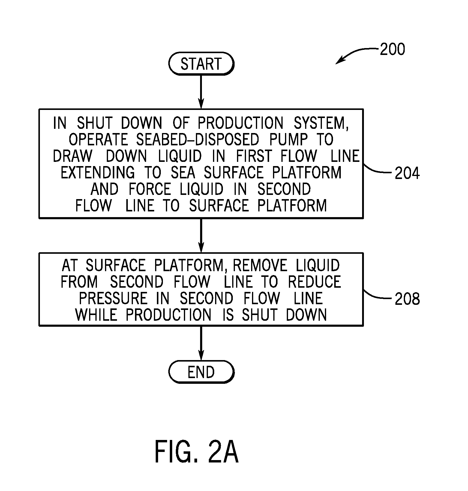
[0037] Thus, referring to FIG. 2A, in accordance with example implementations, a technique 200 may be used to in a partial or full shut down of production for a subsea production system. The technique 200 includes operating (block 204) a seabed-disposed pump to draw down liquid in a first flow line extending to a sea surface platform and force liquid in a second flow line to the platform. The technique 200 includes removing (block 208) liquid from the second flow line to reduce pressure in the second flow line while production is shut down.
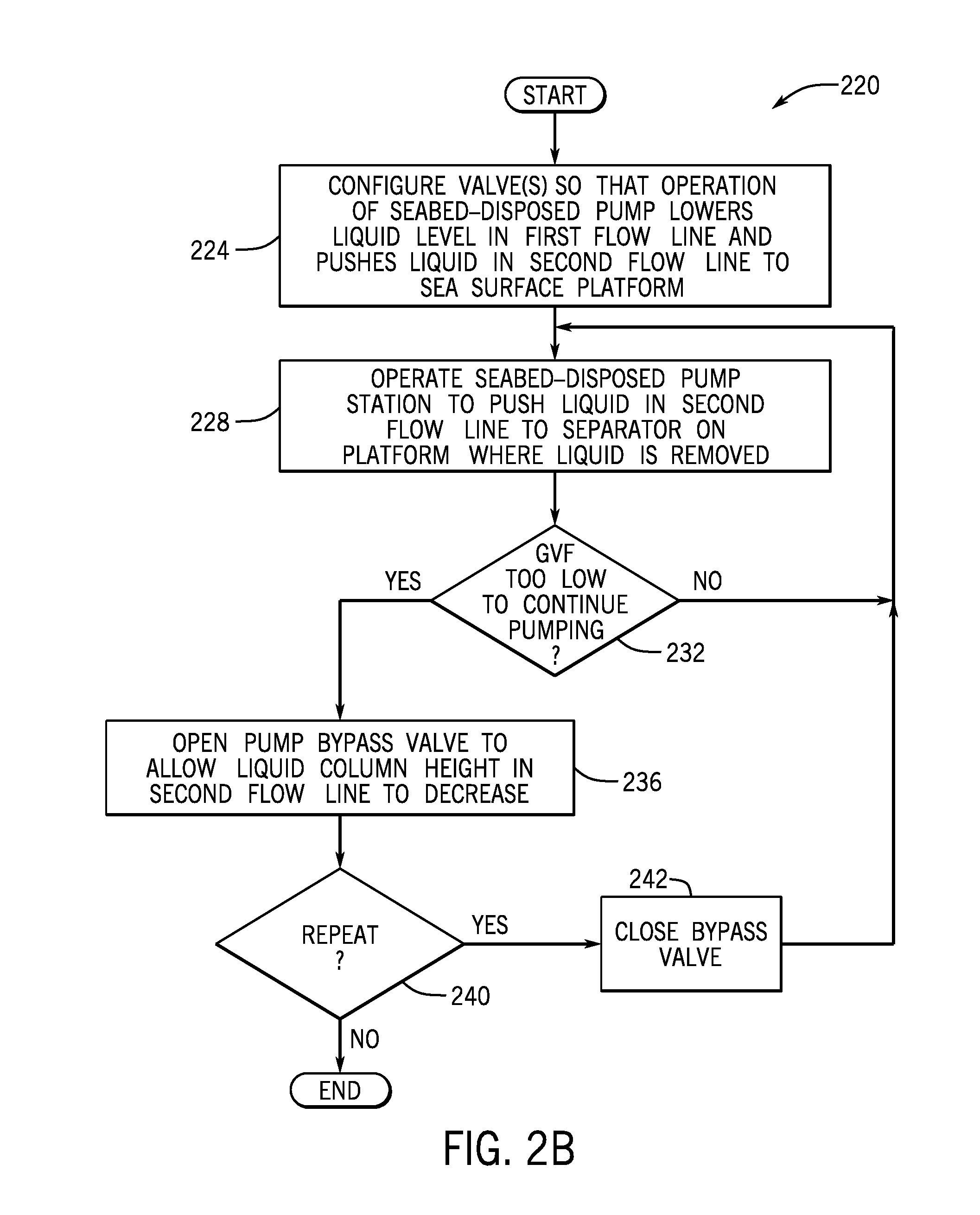
[0038] More specifically, in accordance with example implementations, a technique 220 that is depicted in FIG. 2B may be used for purposes of shutting down production from a subsea well in a manner that reduces a pressure in a production flow line. In this manner, referring to FIG. 2B, the technique 220 includes configuring (block 224) valve(s) so that operation of a seabed-disposed pump station lowers the liquid level of a first flow line and pushes liquid in a second flow line to sea surface platform. The technique 220 includes operating (block 228) the seabed-disposed pump station to push liquid the second flow line to separator on the platform where the liquid is removed. The operation of the pump station continues until a determination is made (decision block 232) that a suction pressure limit has been reached (e.g., the GVF is too low to continue pumping). After this limit is reached, the technique 220 includes opening (block 236) a pump bypass valve to allow the liquid column height in the second flow line to decrease. In accordance with example implementations, at this point, the static pressure caused by the liquid column is now removed, and the system is at a boiling/separator pressure down to the gas-liquid interphase. If, in accordance with example implementations, a determination is made (decision block 240) that after the liquid backflow, liquid still exists in the second flow line, then the bypass valve is closed (block 242) and control returns to block 228 to repeat the pumping process.
[0039] It is noted that the techniques 200 (FIG. 2A) and 220 (FIG. 2B) may be used to reduce the pressure in one or multiple flow lines, as production may continue in one flow line, while production is halted in other flow line. For example, referring to FIG. 1, in accordance with some implementation, flow may be halted in flow line segment 126-1, while flow continues in segment 124-1, or vice versa.
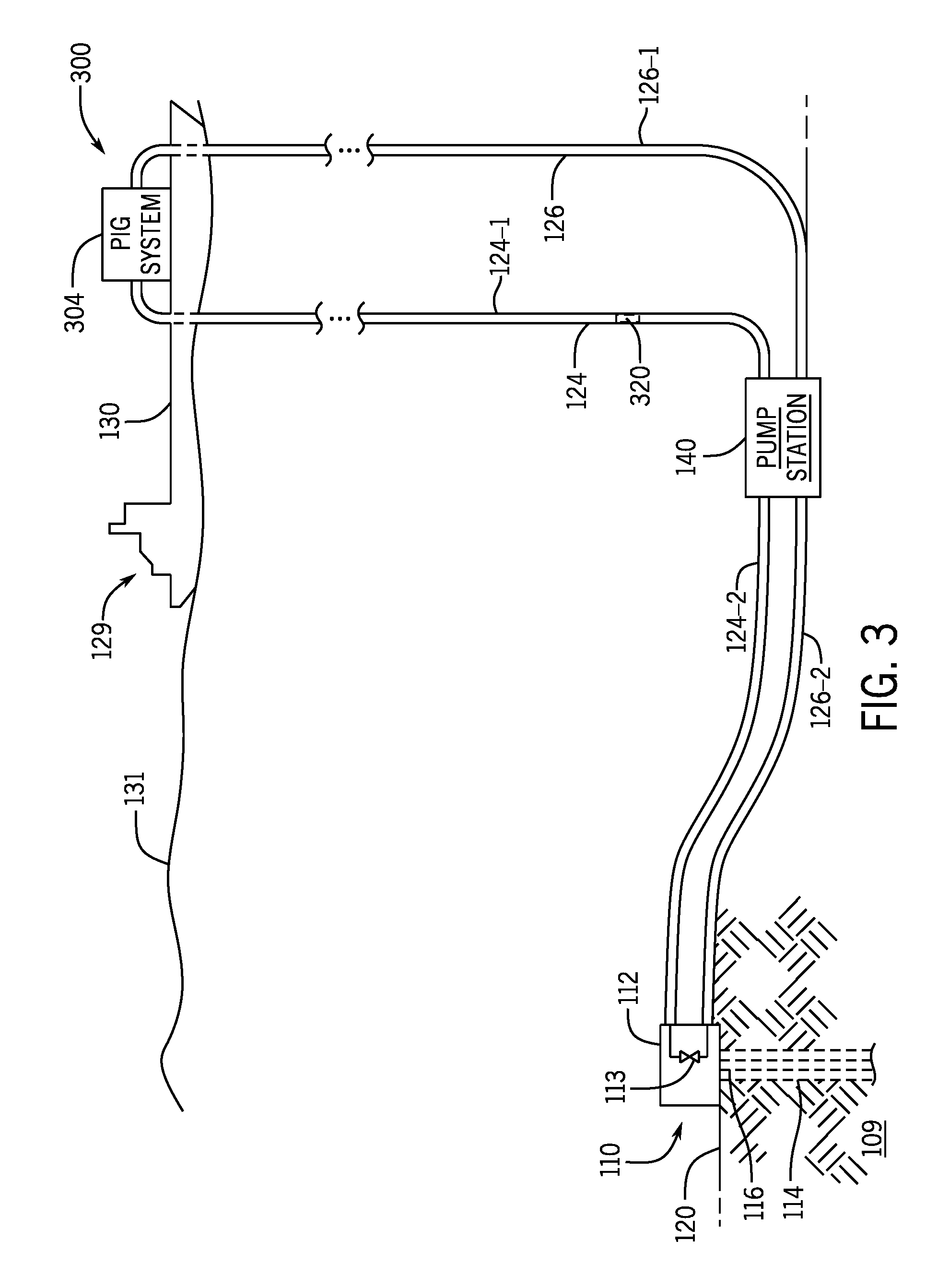
[0040] In accordance with example implementations, a seabed-disposed pump station, such as the pump station 140, may be used to assist in launching and retrieving pigs to clean out hydrate formations (as well as other obstructions) from flow lines. More specifically, FIG. 3 depicts a subsea production system 300 that has similar components to the subsea production system 100 of FIG. 1. In this manner, in FIG. 3, similar reference numerals are used to denote similar components to the subsea production system 100, whereas different reference numerals are used to denote different components. In particular, the subsea production system 300 includes a pig launching and retrieval system 304 that is disposed on the surface platform 129. As described herein, the seabed-disposed pump station 140 may be operated for purposes of assisting in communicating a pig 320 through flow lines of the subsea production system 300 in a round trip that begins and ends at the surface platform 129. In particular, in accordance with example implementations, the pump station 140 may be operated to pull a pig 320 that is launched from the pig launching and retrieval system 304 through the flow line 124 (as depicted in FIG. 3); reroute the pig 320 to the flow line 126; and push the pig 320 back through the flow line 126 to the pig launching and retrieval system 304.
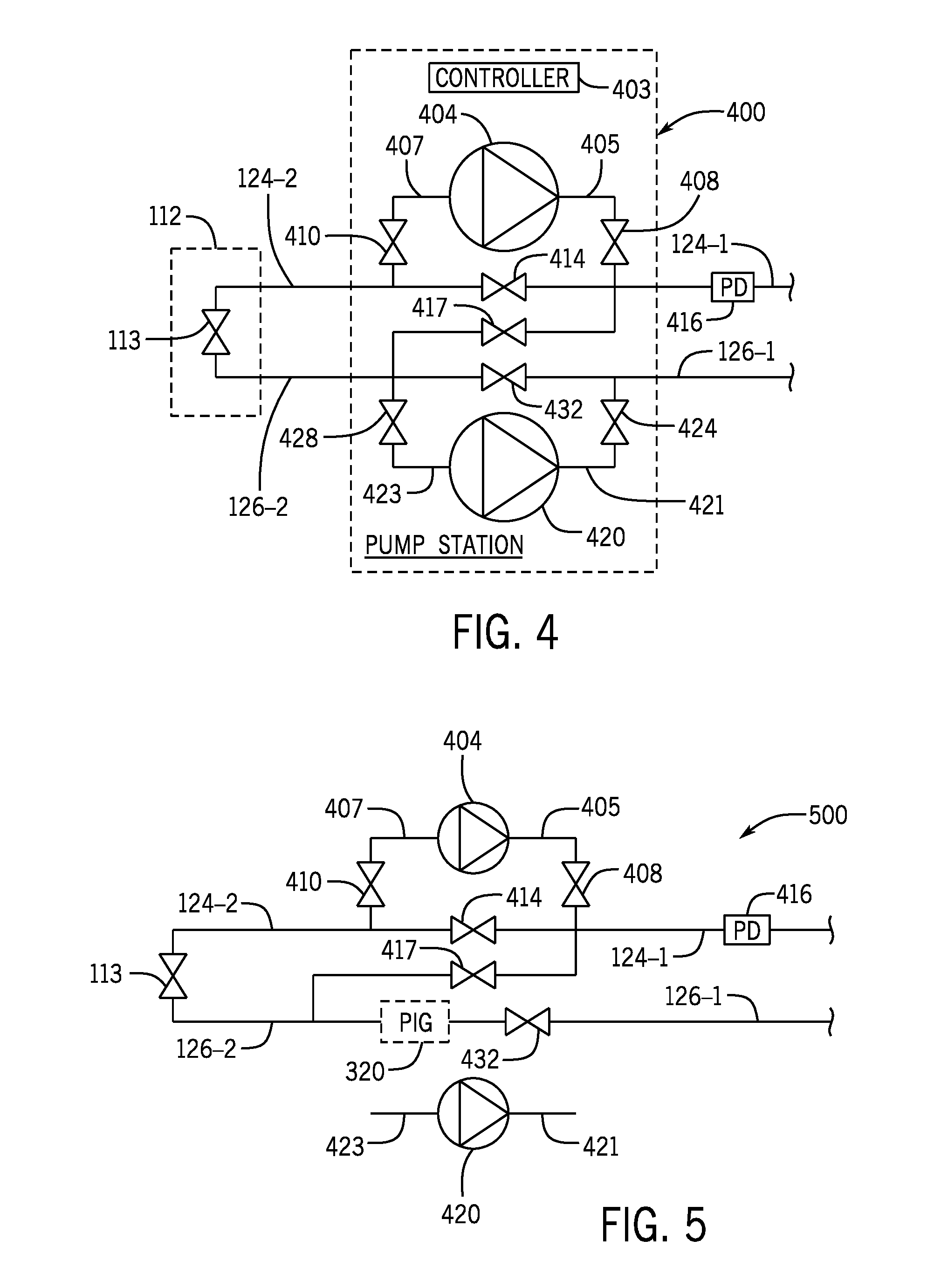
[0041] In accordance with some implementations, the pump station 140 may have an implementation that is depicted in FIG. 4. For this example implementation, the pump station 140 includes a first pump 404 and a second pump 420. In general, the first pump 404 may have a discharge outlet 405 that may be selectively connected to the flow line segment 124-2 by an isolation valve 408, and the pump 404 may have a suction inlet 407 that may be selectively connected to the flow line segment 124-2 via an isolation valve 410. The pump 404 has an associated bypass valve 414 that is connected between the flow line segments 124-1 and 124-2. In general, to connect the pump 404 inline with the flow line 124, the isolation valves 408 and 410 are opened, and the bypass valve 414 is closed; and to bypass the pump 404, the isolation valves 408 and 410 are closed, and the bypass valve 414 is opened.
[0042] The pump 420 may have a discharge outlet 421 that may be selectively connected to the flow line segment 126-2 by an isolation valve 424, and the pump 420 may have a suction inlet 423 that may be selectively connected to the flow line segment 126-2 via an isolation valve 428. The pump 420 has an associated bypass valve 432 that is connected between the flow line segments 126-1 and 126-2. In general, to connect the pump 420 inline with the flow line 126, the isolation valves 424 and 428 are opened, and the bypass valve 432 is closed; and to bypass the pump 420, the isolation valves 424 and 428 are closed, and the bypass valve 432 is opened. The pump station 140 may further include a crossover valve 417 that may be opened, as further described herein to connect the flow line segments 124-1 and 126-1 together.
[0043] It is noted that the pump station 140 may include other and/or additional components, in accordance with further example implementations, such as a single pump, more than two pumps, flow regulators and so forth. The components of the pump station 140 illustrated in FIG. 4, the pump station depicted in other figures, and the other pump stations that may be depicted herein are merely shown for purposes of illustrating an example implementation of a seabed-disposed pump station that may be used to assist in communicating a pig through a flow line. Thus, many other implementations are contemplated, which are within the scope of the appended claims.
[0044] For purposes of detecting the pig 320 when the pig 320 is in vicinity of the pump inlet 423, the pump station 140 may include a pig detector 416. For the implementation that is depicted in FIG. 4, the pig detector 416 is connected to the flow line segment 124-1 for purposes of detecting the pig 320 when the pig 320 is upstream of the crossover valve 417.
[0045] In accordance with example implementations, the pig detector 426 may be a physical contact-based detector that sense physical contact with the pig 320 inside the flow line. In accordance with further example implementations, the pig detector 416 may be constructed to sense the presence of the pig 320 without physically contacting the pig 320. As examples, the pig detector 416 may detect the pig 320 using an acoustic energy detected via an acoustic sensor, detect the pig 320 using a change in a magnetic field detected using a wire coil, and so forth.
[0046] For purposes of regulating operations of the pump station 140, such as pigging operations, operations involving shutting down the pump station 140 (shutting down the pump station 140 using techniques 200 (FIG. 2A) and/or 220 (FIG. 2B), for example) and possibly other operations, the pump station 140 may include a controller 403. In accordance with some implementations, the controller 403 may be constructed to sequence the pump station 140 through various states involved in these operations. For example, in accordance with some implementations, the controller 403 may have a telemetry interface to communicate with the surface platform 129 for purposes of receiving commands to configure the particular state of the station 140 and selectively turn on the pumps 404 and 420. More specifically, to shut down the subsea system, an operator at the platform 129 may communicate a command to the controller 403 may operate the pump 420, the bypass valve 432 and other valves of the pump station 104 to perform the techniques 200 and 220 to lower the pressure in flow lines.
[0047] As another example, for a pigging operation, an operator at the surface platform 129 may communicate a command to the controller 403 to place the pump station 140 in an initial state that is associated with the pigging operation in which the pump 420 is operated to draw the pig 320 through the flow line 124 to the pump station 104. The controller 403 may be coupled to the pig detector 416 so that the controller 403 automatically stops the pump 420 in response to detection of the pig 320. Moreover, in accordance with some implementations, either via control signaling from the surface platform 129 or autonomous operation, the controller 403 may place the pump station 140 in a state and operate the pump station 140 (as described herein) to move the pig 320 to the outlet side of the pump 420. Subsequently, via control signaling from the surface platform 129 or autonomous operation (depending on the particular implementation), the controller 403 may place the pump station 140 in a state (described herein) to allow the pump 420 to push the pig 320 through the flow line 126; and then the controller 403 may cause the pump 420 to resume operation to push the pig 320 through the flow line 126 back to the surface platform 129.
[0048] The controller 403 may have many different forms, depending on the particular implementation. In this manner, the controller 403 may disposed inside the pump station 140 (as schematically depicted in FIG. 4). However, in accordance with further implementations, the controller 403 may be located in other seabed equipment, may be located on the surface platform 129, may be a distributed system that is located on the sea bed and at the surface platform 129, may be wholly or partially remotely located at a location other than the subsea production system 300, and so forth. In accordance with some implementations, the controller 403 may include a telemetry interface and one or multiple processors (one or multiple central processing units (CPUs), one or multiple CPU processing cores, and so forth) that execute machine executable instructions (software) to control the pump station 140 as described herein. These instructions may be stored in a non-transitory storage medium, such as semiconductor-based storage, magnetic-based storage, optical storage, and so forth. Moreover, in accordance with further example implementations, the controller 403 may include a dedicated hardware circuit to perform one or multiple functions of the controller 403, such as a field programmable gate array (FPGA) or application specific integrated circuit (ASIC). In yet further example implementations, the controller 403 may be a hydraulic controller that responds to hydraulic stimuli that are communicated from the platform 129.
[0049] In accordance with example implementations, to begin a pigging operation to clean out flow lines of the subsea production system 300, the pig 320 may be placed inside the flow line 124 at the platform 129 (see also FIG. 3) via the pig launching and retrieval system 304 (see also FIG. 3); and the pump 420 of the subsea pump station 140 may then be operated to draw the pig 320 through the flow line segment 124-1 toward the pump station 140. For this purpose, the isolation valves 408 and 410 are closed to isolate the pump 404, which is turned off. Moreover, the bypass valve 414 for the pump 404 is opened; the valve 113 of the wellhead 112 (other valve/manifold path) is opened to connect the flow line segments 124-2 and 126-2 together; the isolation valves 424 and 428 for the pump 420 are opened; the crossover valve 417 is closed; and the bypass valve 432 is closed.
[0050] In this state, the operation of the pump 420 allows the pig 320 to be drawn through the flow line segment 124-1 toward and into the pump station 140. The pig detector 416 may be used to detect when the pig 320 is in proximity of the crossover valve 417 so that the pump 420 may be momentarily stopped and other measures employed to move the pig 320 from the inlet side to the outlet side of the pump 420 before operation of the pump 420 resumes to push the pig 320 through the flow line 126 back to the surface platform 129.
[0051] In accordance with some implementations, the pump 404 of the pump station 140 may be used to push the pig 320 to the outlet side of the pump 420. In this manner, in accordance with further example implementations, the pump station 140 may be placed in a state 500 that is depicted in FIG. 5. In the state 500, the bypass valve 432 is opened; the isolation valves 408 and 410 are opened; the bypass valve 414 is opened; and the crossover valve 417 is opened. The crossover valve 417 establishes communication between the discharge outlet 405 of the pump 404 and the inlet 423 of the pump 420. Therefore, the pump 404 may be operated to push the pig 320 to the outlet side of the pump 420. The pump 404 may then be halted, the bypass valve 432 may be closed, and the isolation valves 424 and 428 (see FIG. 4) may be opened so that pump 420 may be operated to push the pig 320 back to the surface platform 129.
[0052] In accordance with further example implementations, the pump station 140 may include a pigable check valve that forms a shunt path between the flow line segments 124-2 and 124-6 fora more compact design.
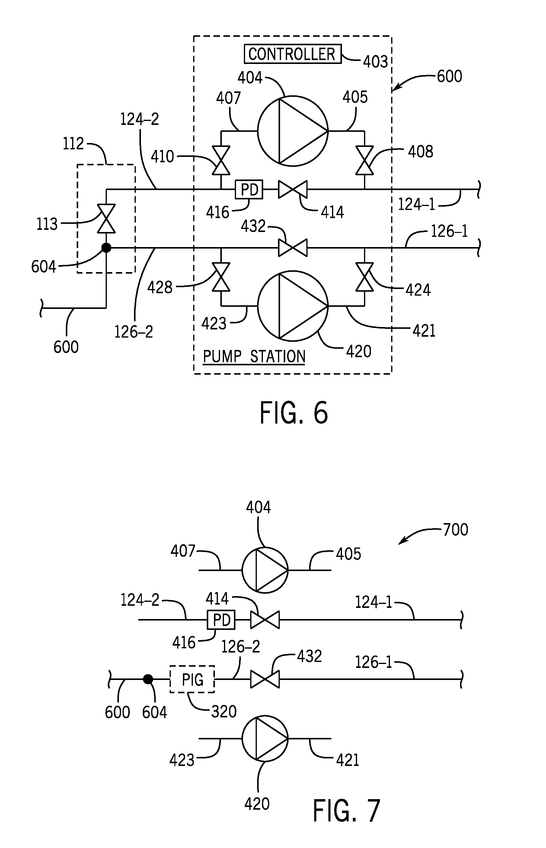
[0053] Referring to FIG. 6, in accordance with further example implementations, a pump station 600 may be used in place of the pump station 140, with similar reference numerals being used in FIG. 6 to components that the pump stations 140 and 600 share in common. The pump station 600 includes a service fluid injection port 604 to push the pig 320 from the inlet to the outlet side of the pump 420. More specifically, in accordance with example implementations, the injection port 604 may be, for example, a service fluid injection port associated with an injection line 600. In this regard, the injection line 600 may be used for purposes of providing a service fluid that is communicated from the surface platform 129 for purposes of injecting service fluid into the well, and the injection line 600 may be used for purposes of introducing a service fluid into the flow line segment 126-2 to push the pig 320 to the outlet of the pump 420. It is noted that depending on the particular implementation, the service fluid may be a gas or a liquid (methanol, methanol ethylene glycol (MEG) or triethylene glycol (TEG), as a few examples).
[0054] In this manner, referring to FIG. 7 in conjunction with FIG. 6, in accordance with example implementations, instead of using the pump 404 to push the pig 320 to the outlet 421 of the pump 420, the pump station 140 may be placed in a state 700 which both pumps 404 and 420 are isolated, and service fluid is injected at the port 604 to move the pig 320 through the bypass valve 432 to the outlet side of the pump 420. After this occurs, the pump station 140 may be configured in a state, as described above, to allow the pump 420 to resume operation and push the pig 320 through the flow line 126 to the surface platform 129.
[0055] In accordance with further example implementations, a fluid may be injected by a remotely operated vehicle (ROV). For example, the ROV may have a pump and a reservoir that stores a fluid. In accordance with example implementations, the ROV may connect (e.g., hot stab) into a connection port of the pump station (or a connection port near the pump station), which allows the ROV to pump the fluid stored in its reservoir into a flow line to push the pig through the pump station.
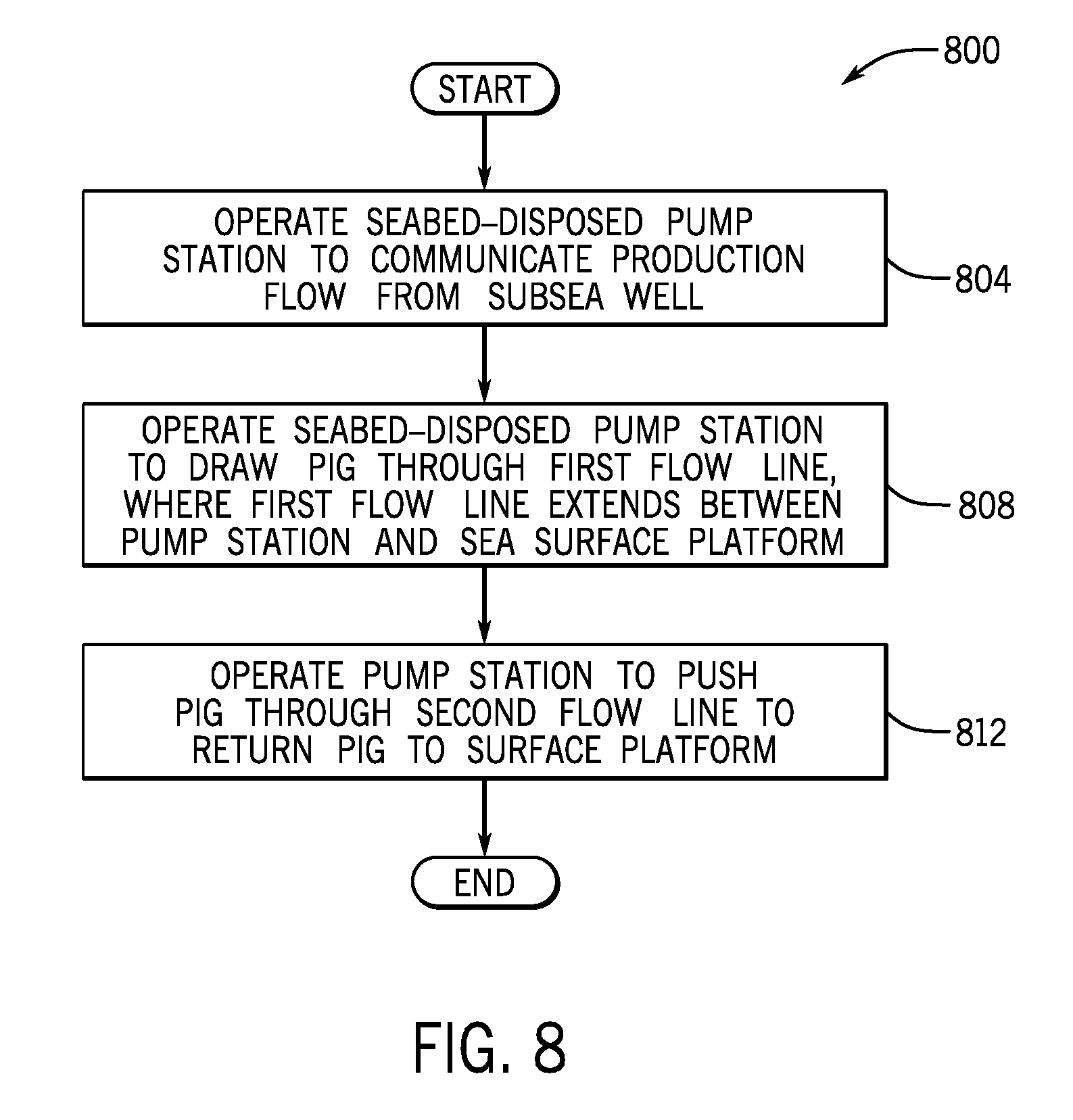
[0056] Thus, referring to FIG. 8, in accordance with example implementations, a technique 800 includes operating (block 804) a seabed-disposed pump station to communicate a production flow from a subsea well and operating (block 808) the seabed-disposed pump station to draw a pig through a first flow line. The first flow line extends between the pump station and a sea surface platform. The technique 800 includes operating (block 812) the seabed-disposed pump station to push the pig through a second flow line to return the pig to the platform.
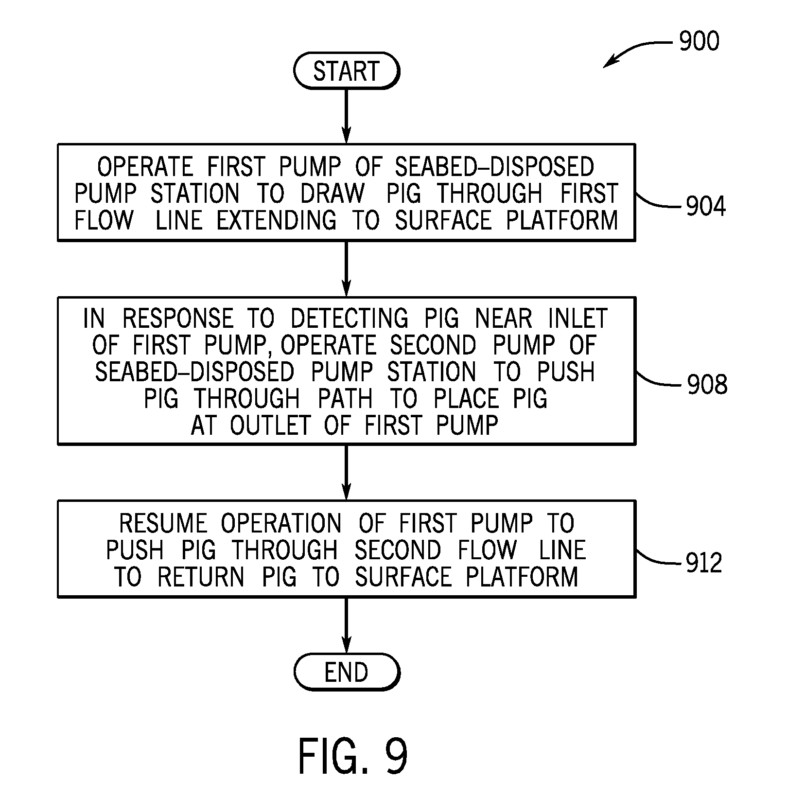
[0057] More specifically, referring to FIG. 9, in accordance with example implementations, a technique 900 includes operating (block 904) a first pump of a seabed-disposed pump station to draw a pig through a first flow line that extends to a surface platform. The technique 900 includes, in response to detecting the pig near an inlet of the first pump, operating a second pump of the seabed-disposed pump station to push the pig through a path to place the pig at an outlet of the first pump, pursuant to block 908. Operation of the first pump may then resume to push the pig through the second flow line to return the pig to the surface platform, pursuant to block 912.
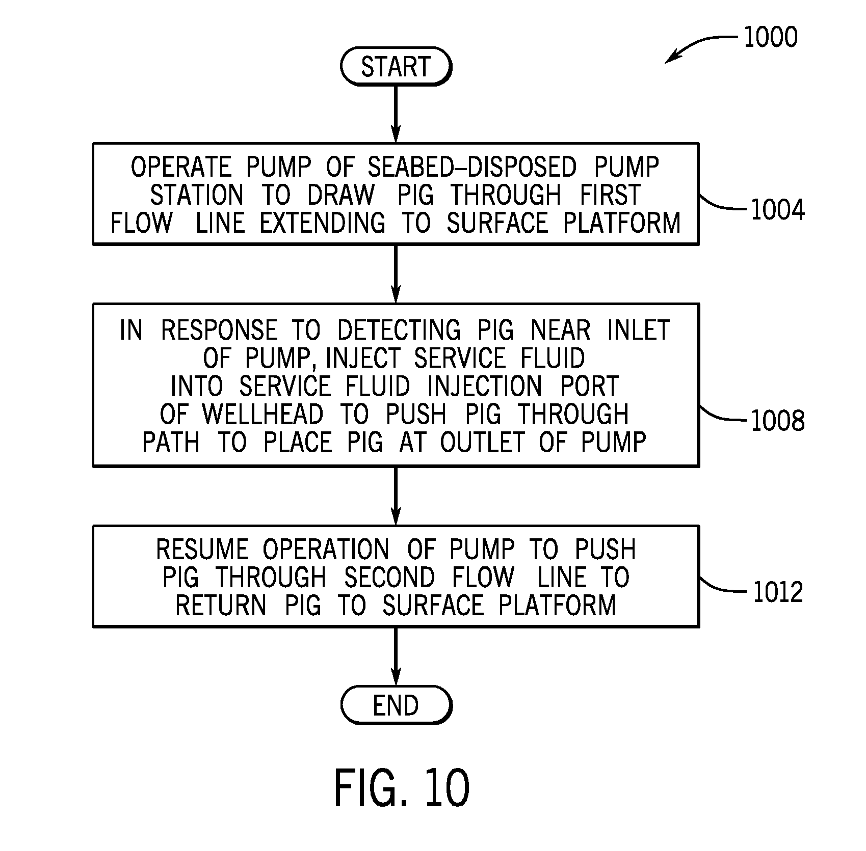
[0058] Referring to FIG. 10, in accordance with further example implementations, a technique 1000 includes operating (block 1004) a first pump of a seabed-disposed pump station to draw a pig through a first flow line that extends to a surface platform. The technique 1000 includes, in response to detecting the pig near an inlet of the first pump, injecting a service fluid into a service fluid injection port of a wellhead to push the pig through a path to place the pig at an outlet of the first pump, pursuant to block 1208. Operation of the first pump may then resume to push the pig through the second flow line to return the pig to the surface platform, pursuant to block 1012.
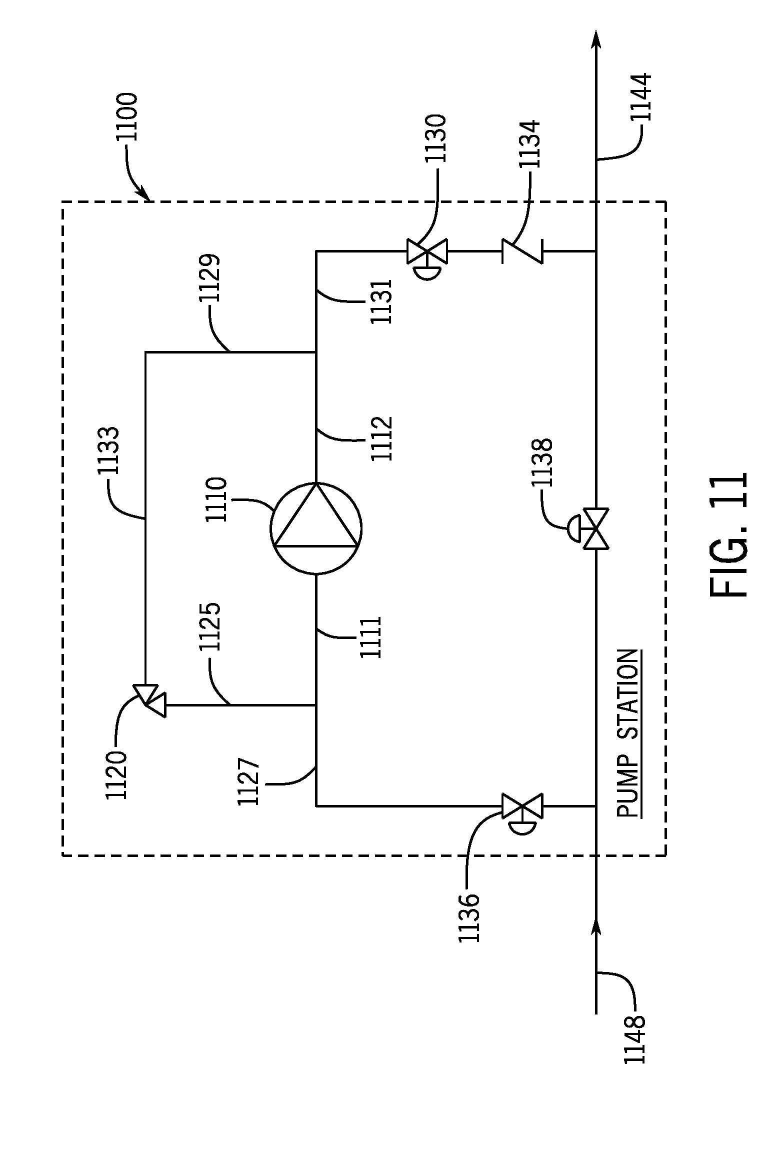
[0059] In accordance with further example implementations, other measures may be employed for purposes of inhibiting and removing hydrate formations. For example, referring to FIG. 11, in accordance with some implementations, a seabed-disposed pump station 1100 may be used in place of the other pump stations described above. In general, the pump station 1100 includes at least one pump 1110, and the pump station 1100 has an inlet 1148 and an outlet 1144. The pump 1110 has a recirculation flow path 1133 that operates when the pump station 1100 is placed in a bypass recirculation mode. In this regard, the pump 1110 has an inlet 1111 and an outlet 1112. The outlet 1112 is connected by a connection (a T connection, a Y connection or other connection) to an inlet 1129 to the recirculation flow path 1133 and to another flow path 1131 that is connected to an outlet valve 1130. The recirculation flow path 1133 includes a choke valve 1120 that is connected to a T connection to the inlet 1111 and to a flow path 1127 that is connected to an inlet valve 1136. Moreover, a bypass valve 1138 may be connected between the inlet 1148 and the outlet 1144.
[0060] It is noted that FIG. 11 merely depicts an example configuration of the pump station. Other variations are contemplated and are within the scope of the appended claims. For example, in accordance with further implementations, the recirculation path 1133 may branch out to/from the main flow line (may branch out and be connected upstream of the inlet 1148 and/or downstream of the outlet 1144, as examples).
[0061] In accordance with example implementations when the pump station 1100 is not pumping production fluid, the pump station 1100 may be placed in a bypass mode of operation. In this mode of operation, the pump 1110 operates to produce a flow through the recirculation path 1133; and the pump 1110 may be connected in a local recirculation flow path (i.e., a path extending between the outlet 1144 and inlet 1148). The local recirculation flow path may be, for example, a path entirely inside the pump station 1100 or may be a path that extends outside of the pump station 1100. As examples, the path may extend outside the pump station by up to ten feet, up to twenty feet, up to fifty feet, or even farther, depending on the particular implementation. The local recirculation flow path may be created by, for example, actuating valves or other flow control paths to couple together the outlet 1144 and inlet 1148. The operation of the pump 1110 in the bypass mode produces thermal energy, and the recirculating flow acquires thermal energy from the pump 1110 and transfers this thermal energy along the local recirculation flow path. The local recirculation flow path, in accordance with example implementations, may extend in a path that is sufficiently short enough to allow the acquired thermal energy to be used to remove hydrate formations along the path.
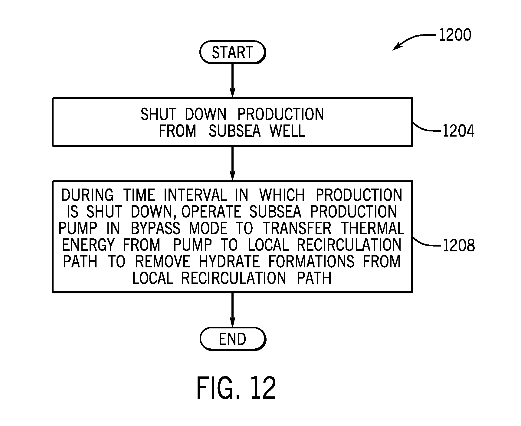
[0062] Thus, referring to FIG. 12, in accordance with example implementations, a technique 1200 includes shutting down production from a subsea well, pursuant to block 1204 and during a time interval in which the production is shut down, operating (block 1208) a subsea production pump in a bypass mode to remove hydrate formations in a flow path.
[0063] While the present disclosure has been described with respect to a limited number of implementations, those skilled in the art, having the benefit of this disclosure, will appreciate numerous modifications and variations therefrom. It is intended that the appended claims cover all such modifications and variations.
* * * * *
D00000
D00001
D00002
D00003
D00004
D00005
D00006
D00007
D00008
D00009
D00010
D00011
XML
uspto.report is an independent third-party trademark research tool that is not affiliated, endorsed, or sponsored by the United States Patent and Trademark Office (USPTO) or any other governmental organization. The information provided by uspto.report is based on publicly available data at the time of writing and is intended for informational purposes only.
While we strive to provide accurate and up-to-date information, we do not guarantee the accuracy, completeness, reliability, or suitability of the information displayed on this site. The use of this site is at your own risk. Any reliance you place on such information is therefore strictly at your own risk.
All official trademark data, including owner information, should be verified by visiting the official USPTO website at www.uspto.gov. This site is not intended to replace professional legal advice and should not be used as a substitute for consulting with a legal professional who is knowledgeable about trademark law.