Loop-Forming Method, Device and System Component
Wornle; Martin ; et al.
U.S. patent application number 15/748918 was filed with the patent office on 2019-01-03 for loop-forming method, device and system component. The applicant listed for this patent is Groz-Beckert KG, Santoni S.P.A. Invention is credited to Marco Andreoli, Stefano Rizzi, Martin Wornle.
| Application Number | 20190003090 15/748918 |
| Document ID | / |
| Family ID | 53761288 |
| Filed Date | 2019-01-03 |


| United States Patent Application | 20190003090 |
| Kind Code | A1 |
| Wornle; Martin ; et al. | January 3, 2019 |
Loop-Forming Method, Device and System Component
Abstract
A loop-forming process includes moving at least two system components (11, 12) in one groove (16) of a needle bed in a first longitudinal direction (y). The system components contact threads (23) for forming loops. At least one spacer (10) is placed between two adjacent system components (11, 12) moved in the groove (16), whereby this spacer (10) contributes to distance (21) adjustment between loop-forming portions in the direction (.chi.) of the grooves' (16) width. The at least one spacer (10) moves together with a first one of the two adjacent system components (11, 12) and is at least temporarily moved inside a section (41) of the longitudinal (y) extension where the spacer (10) and the second system component (12) are in mechanical contact and/or in which the spacer (10) is in mechanical contact with a second spacer (10) moved together with the second of the two system components (11, 12).
| Inventors: | Wornle; Martin; (Mossingen, DE) ; Andreoli; Marco; (Castegnato Brescia, IT) ; Rizzi; Stefano; (Brescia, IT) | ||||||||||
| Applicant: |
|
||||||||||
|---|---|---|---|---|---|---|---|---|---|---|---|
| Family ID: | 53761288 | ||||||||||
| Appl. No.: | 15/748918 | ||||||||||
| Filed: | July 27, 2016 | ||||||||||
| PCT Filed: | July 27, 2016 | ||||||||||
| PCT NO: | PCT/EP2016/067914 | ||||||||||
| 371 Date: | January 30, 2018 |
| Current U.S. Class: | 1/1 |
| Current CPC Class: | D04B 35/04 20130101; D04B 15/14 20130101; D04B 15/06 20130101; D04B 15/10 20130101; D04B 35/02 20130101 |
| International Class: | D04B 35/04 20060101 D04B035/04; D04B 15/06 20060101 D04B015/06; D04B 15/10 20060101 D04B015/10 |
Foreign Application Data
| Date | Code | Application Number |
|---|---|---|
| Jul 30, 2015 | EP | 15179093.8 |
Claims
1. Loop-forming process, comprising: moving at least two system components (11, 12) in one groove (16) of a needle bed relative to said needle bed (14) in a first direction (y) which corresponds to longitudinal direction, said system components (11, 12) contacting threads (23) for forming loops with their loop-forming portions (20, 24), contributing to adjusting a distance (21) between the loop-forming portions (20, 24) with at least one spacer (10) placed between two adjacent system components (11, 12) of the system components, the distance adjusted in a second direction (x) which corresponds to a direction of a width of the grooves (16) of the needle bed (14), whereby said at least one spacer (10) abstains from the loop-forming process, moving the at least one spacer (10) together with a first one of said two adjacent system components (11, 12), at least temporarily moving the at least one spacer (10) inside a section (41) of the longitudinal (y) extension of the groove (16), wherein one or both of: a first spacer of the at least one spacer (10) and a second one of said two adjacent system components (12) are in mechanical contact with each other, and the first spacer (10) is in mechanical contact with a second spacer (10) of the at least one spacer which is moved together with the second one (12) of said two adjacent system components (11, 12).
2. Loop-forming process according to claim 1 further comprising: moving the needle bed (14) relative to a cam holder of the knitting machine with a first velocity (vk), so that butts (17) of the system components (11, 12) pass through cams (18) connected with a cam holder of the loop-forming machine, whereby the butts (17) receive force for movement of the system components (11, 12), the system components (11, 12) performing periodic movements in their longitudinal direction (y) and that the system components (11, 12) reach minima and maxima during these movements, the loop-forming portions (20, 24) of a first adjacent system component (11) and a second adjacent system component (12) of the two adjacent system components reaching minima and maxima (37) of their movements with a delay of time bigger than half of a first quotient or equal to said first quotient, whereby the first quotient is a quotient of a distance (21) between the loop-forming portions of the two adjacent system components in the second direction (x) and the first velocity (vk).
3. Device for loop-forming, comprising: a needle bed, a plurality of system components (11, 12) comprising loop-forming portions (20, 24) and configured to be involved in loop-forming at least for a period of time during a loop forming process, the needle bed (14) is provided with a plurality of grooves (16) which have an extension in a first direction (y) which corresponds to a longitudinal direction (y) of the system components (11, 12), whereby said system components (11, 12) are movably arranged in said grooves (16) and individual grooves house at least two system components (11, 12), at least one spacer (10) configured to contribute to adjustment of distance (21) between the loop-forming portions (24) of two adjacent system components (11, 12) of the plurality of system components of one of the grooves (16) in a second direction (x) which corresponds to a direction of width of the grooves (16) of the needle bed (14), wherein a first spacer of the at least one spacer (10) is immovably connected with at least a first one of said two adjacent system components (11, 12) at a position of the longitudinal extension (y) of the system components (11, 12) which is during the loop-forming process at least temporarily housed by a section of one of the grooves (16), wherein one or both of: the first spacer (10) and a second one (12) of the adjacent system components (12) are in mechanical contact with each other, and the first spacer (10) is in mechanical contact with a second spacer (10) of the at least one spacer which is immovably connected with the second one of said two adjacent system components (12).
4. Device for loop-forming according to claim 3 wherein a first one of the two adjacent system components (11, 12) is provided with and immovable connected to one of the at least one spacer (10).
5. Device for loop-forming according to claim 3 wherein the two system components (11, 12) are provided with two spacers (10) of the at least one spacer, and a first of the two spacers (10) is immovably connected with the first (11) of said two adjacent system components and a second of the two spacers (10) is immovably connected with the second (12) of said two adjacent system components.
6. Device for loop-forming according to claim 3, wherein the distance (21) in the second direction (x) between the loop-forming portions (20, 24) of the two system components (11, 12) of one groove (16) is equal to at least one distance between the loop-forming portions of two other adjacent system components of the needle bed (14) in the second direction (x), whereby the two other adjacent system components (11, 12) are separated by an immovable wall (15) of a groove (16) of a needle bed (14).
7. Device for loop-forming according to claim 3, wherein the distance in the second direction (x) which is adjusted by the at least one spacer (10) between the loop-forming portions (20, 24) of the two system components (11, 12) is approximately equal to a width of a shank (39) in the second direction (x) of at least one of the two adjacent system components (11, 12).
8. Device for loop-forming according to claim 3, wherein the at least one spacer (10) is integral with the system component (11, 12) with which the at least one spacer (10) is immovably connected.
9. Device for loop-forming according to claim 3 wherein the at least one spacer (10) comprises a bend (51) of a shank (39) of the first one of the two adjacent system components (11, 12) with which it is immovably connected.
10. Device for loop-forming according to claim 3 wherein the at least one spacer (10) comprises a bend (51) of a shank (39) of the first one of the two adjacent system components (11, 12) with which it is immovably connected and that at least a section of the bend's (51) side surface which is directed towards the second one of the adjacent system components (11, 12) is parallel to a surface of an immovable wall (15) of the groove (16) in which the respective system components (11, 12) are housed.
11. Device for loop-forming according to claim 3 wherein the at least one spacer (10) is an additional part (38) connected in a mating process with the one of the two adjacent system components (11, 12) with which it is immovably connected.
12. Device for loop-forming according to claim 11 wherein the at least one additional part (38) comprises materials which are not included in the system component (11, 12).
13. Device for loop-forming according to claim 12 wherein the additional part is connected to the system component (11, 12) with which the spacer (10) is connected by at least one of: splice, weld joint (42), solder joint, splint (44), or combinations thereof.
14. System component for loop forming which comprises: a shank (39) configured to glide in a needle groove (16) of a needle bed (14) which essentially extends in a first longitudinal direction (y) and has a width in a second direction (x), means for loop forming (20, 24) which are placed on one longitudinal end of the shank (39), a butt (17) configured to interact with a cam (18) of a knitting machine, whereby the butt (17) has an extension in a third direction (z) which corresponds to a height direction (z) of the shank and overtowers the shank (39), a spacer (10) which is placed immovably on the shank (39) wherein a width of the butt (17) in the second direction (x) is smaller than a maximum combined extension of the shank (39) and the spacer (10) in the second direction (x) at at least one position of an extension (45) of the butt (17) in the first direction (y).
15. System component for loop forming according to claim 14 wherein the butt (17) has a first width (46) in the second direction (x) in an end section (43) of its extension (45) in the first direction (y), the butt has a second width (47) in the second direction (x) in at least one middle section (49) of its extension (45) in the first direction, and the second width (47) is bigger than the first width (46).
Description
[0001] Various types of knitting machines are well known. Circular knitting machines, flat knitting machines and warp knitting machines belong to the most important types of these machines.
[0002] Knitting machines usually comprise at least one needle bed for supporting knitting tools. Needle beds of circular knitting machines are often called "cylinder" because of their cylindrical shape. In the present publication the impression "needle bed" refers to all kinds of devices that support knitting tools no matter if they are flat, cylindrical or whatever.
[0003] Knitting tools are for example needles, sinkers or the like. Knitting tools are parts of knitting machines that are directly involved in the loop forming process and hereby have contact to threads. The different knitting tools grasp, lead or hold down the threads. In the present publication all knitting tools are called "system components".
[0004] One kind of special system components are slider needles. The publication DE 698 03 142 T2 shows a slider needle. The respective slider's profile is u-shaped in the plane perpendicular to the slider's movement. As a result, the two legs of the u-shaped sliders partially embrace the shank of the needle on which the respective slider is moved. One could also say that any leg of the sliders is partially arranged between the needle shank of the needle on which the respective slider slides and the adjacent needle or the adjacent needle shank. During the knitting process there are relative movements between the needle shank and the slider. Hereby, the slider temporarily closes the opening for the thread inside the hook or carries the loop along the needle shank. In doing so the slider gets regularly in contact with the thread.
[0005] During knitting the various types of system components acting in different types of knitting machines have relative movements to at least one kind of needle bed. These relative movements in channels of the needle bed generate some problems which are inherent in most modern knitting machines:
[0006] High frictional load between system components and needle bed or even sticking of the system components in the channels. The friction causes wear on system components and needle bed and generates undesirable heat in the knitting machine.
[0007] In publication DE 10 2013 104 189 A1 the problem of sticking of sinkers in the channels caused by the not longitudinal components of the actuation of the sinkers' butt is discussed. This publication proposes to use two sinkers of different length in one common groove to solve that problem.
[0008] The publication EP 0 672 770 A1 shows a flat knitting machine for knitting a tubular knitted fabric. One of the shown knitting machines uses two needles in one common groove. The needles are provided with transfer elements as blades. The said publication mentions that a spacer can be necessary to prevent interference between the needles caused by the transfer elements. The spacer itself and its mode of operation are not described in more detail.
[0009] The publication DE 33 11 361 A1 shows a knitting machine comprising needles and sinkers for loop-forming that move in the same longitudinal direction. Said knitting machine comprises a first cylinder placed in a lower region of the knitting machine where the needles are supported in channels. The needles used have a very long shank so that the hook is always far outside the needle cylinder in an upward direction. On top of the needle cylinder there is an additional cylinder for supporting the sinkers and the sinkers are short compared to the needles. The aforementioned long shanks of the needles are on top of the trick walls of the channels of the cylinder for the sinkers and therefore between the sinkers. The means for loop-forming of the needles and the sinkers (hook, holding-down-edge and knock-over-edge) commonly extend in a region of the knitting machine where loops are formed. Said region is located upside of the cylinder of the sinkers. The needles and the sinkers are hereby at least partially separately guided in channels and thus the friction is reduced compared to an arrangement in which needles and sinkers are solely guided in common channels.
[0010] The application DE 197 40 985 A1 shows recesses on the flat sides of knitting needles or on the walls of channels of a needle bed. The recesses are only provided in certain regions of the side faces of the knitting needles and not on the full length of the side faces of the needles. As a result of these measures, the surface area of the contacting surfaces of the said elements of the knitting process is reduced. Thus the energy consumption and the heat generation in the machine are reduced.
[0011] The application EP1860219A1 shows knitting needles with a relatively thin shank. Some of the figures of this publication show in a cross-sectional view that the needles are arranged askew or diagonally in the needle grooves so that only one of the two top corners and the opposing bottom corner of the needles' cross section touch the needle groove. The surface area of the contacting surfaces is once again reduced so that the energy consumption of the system decreases. The heat generation is thus also reduced.
[0012] There are other patent publications which show knitting machines in which the side faces of the shanks of adjacent needles are in contact with each other ("side-by-side needles"): [0013] The DE610511B discloses two very similar types of needles. Both types comprise a thick (in the direction of the width of the needles) and stable rear part which carries the needle butts. The difference between the two needle types is that the first group is provided with a longer rear part than the other type. [0014] The front parts of both types of needles, which support the hook, are relatively thin. [0015] The front parts have the same length. [0016] In the needle beds shown by this publication a segment of the thin front part of each of the needles is guided in a respective slot of the needle bed. Needles of the long type surround groups of needles of the short type. An end segment of the rear part of the long needles is additionally guided by respective slots. The side faces of segments of the thicker rear parts of adjacent needles are in contact with each other. [0017] The DE610511B aims at reducing the costs for grinding the common long needle channels of the needle bed: These long channels are replaced by the above mentioned slots which only cover relatively small segments of the length of the needles. However, this publication fails to teach a knitting device which is apt to the requirements of modern knitting processes: If the knitting beds shown in the DE610511B were subject to modern knitting velocities the needles would be bent. Therefore the needles would become subject to undue wear or the needles would even stick in the respective slot.
[0018] The application WO2012055591A1 shows a knitting machine which was constructed for the following purposes: High gauge, low manufacturing costs and low energy consumption. This publication also shows groups of two needles which are in contact to each other during the knitting process (side-by-side needles): [0019] The rear part of these needles is placed in a joint needle channel so that segments of the side faces of these needles have contact with each other. In its front part this needle channel is bifurcated so that the front parts of the two needles of a needle bed are spaced away from each other. As a result, the front part of each needle is bent during its movements in its length direction. This fact causes wear and energy consumption. Moreover, it is not easy to bend needles with thick shanks.
[0020] Application WO2013041380A1 shows a knitting machine with improved actuation cams for the type of side by side needles shown by the aforementioned WO2012055591A1. The knitting machines can be manufactured at lower costs and they can produce high quality fabrics. However the publication's teaching has the same drawbacks as mentioned before.
[0021] It is the object of the present invention to provide a process and a device for the forming of loops with a reduced energy consumption and heat generation of the knitting machine.
[0022] The above object is achieved with the method according to claim 1, the device according to claim 3 and the system component according to claim 14.
[0023] In most loop-forming processes--including inventive ones--a plurality of needles will be used for forming the respective loops. Usually, there are more than hundred needles involved in a typical loop forming process. One characteristic of the inventive loop forming process is that there is at least one groove which is provided with at least two system components. There can be 2, 3, 4, 5, 6 or even more of these system components in one groove. In the present publication the phrase "system components" means textile tools which are provided with loop forming means like hooks or latches which are in contact with the yarn (or also called threads) and which actively take part in the loop forming process. Therefore the loop-forming means are preferably involved in the forming of loops at least for a period of time during the loop-forming process. Usually such system components are called needles or sinkers.
[0024] The inventive method uses a so-called spacer or spacing means in order to adjust the distance between the loop forming means of two adjacent system components which are moved or housed in one groove. Therefore the word "spacer" is a functional expression which denotes an additional part as well as an integral part which is made of one piece preferably with the respective system component's shank.
[0025] The spacer, however, does not take part in or abstains from the loop forming process. In most cases the distance between the loop forming means of two adjacent system components is a distance in the second direction (x) which corresponds to the direction of the width of the grooves. The person-skilled in the art will understand that this second direction could have a purely linear character if flat knitting machines are concerned. The movements of system parts of circular knitting machines can--however--be described with cylinder coordinates (r, .phi., z). Therefore the direction of the width of the grooves of the channels has circular components (.phi.). However, the direction of the width of the grooves of all knitting machine types shall be denoted with "x" in the present publication.
[0026] As already mentioned, the space between the loop forming means of the two adjacent system components is free of loop forming means which belong to or are actuated by system components of the same grove or even of the same needle bed. As a consequence, the distance which is adjusted by the spacers or by means of the spacers is the width--or the extension in the second direction (x)--of the aforementioned free space between the loop forming means of two adjacent system components of one needle bed. No loop forming means which is actuated by or part of a system component which is moved or housed in the same groove--or expressed in a wider way--which is housed in the same (first) needle bed interferes in this space. On the other hand, loop forming means of other grooves--or broader--another second needle bed which is directed differently may interfere there and cooperate with the loop forming means of the first needle bed so as to form loops. Example: the first needle bed houses knitting needles. The second needle bed houses sinkers which interfere in this space in order to hold down the previously formed loops so that the needles can form new loops.
[0027] However, the distance adjusted by the spacers is free of system components of the same groove or the same needle bed, so that the above definition still applies. Usually the grooves of the first and the second needle bed need to have a different direction so that the system components of the second needle bed or its grooves can cooperate in the way described above. Therefore another definition of the "distance" of the space defined by this distance could say, that there are no loop-forming means in this space or area of the loop forming zone, in which loop forming means which are moved in the same direction reach into.
[0028] The aforementioned spacer is moved together with at least one of said two adjacent system components. "Moved together" means in the present context that the relative velocity between the spacer and the respective at least one system component is nil. It is possible to actively move the spacer this way, however, it is also possible to in any way connect these two elements (spacer and system component) so that they will not move with respect to each other. The respective connection can transfer power between the spacer and the system component. Most advantageously the connection can sustain the amount of power necessary for the movement either of spacer or of the respective system component. The respective connection can be made in several ways and the connection can be adjusted so as to sustain different amounts of power. Another definition for this point could be that the spacer is not relocatable or immovable with regard to the system component with which it is connected. The spacer could also be part of and integral with said system component.
[0029] The spacer and the respective first system component with which it moves is at least temporarily moved inside a section of the groove in which the spacer and the second of the two adjacent components are in mechanical contact with each other. Most advantageously the length of the section or the sections in which the spacer and the second of the two adjacent components and/or the spacer of the second system component are in mechanical contact with each other is equal to 70, 80, 90 or 95% of the system component's length. There are further advantages if the spacers and the system components are the only components moved in the groove on the respective sections of the groove. A different approach is to provide the side surfaces of system components with a plurality of spots or areas which adjust the distance between the system components (for the purposes of the present publication this plurality of spots or areas is also called "spacer"). Such a group consists of at least two and--more advantageously--of at least three members. Therefore these spots are "elevated" with regard to the side surfaces in the x-direction. In this case it is advantageous if the distance between the two spots which are provided with the biggest distance of said plurality of spots (in y-direction) of one side surface is at least equal to 50, 60, 70, 80, 90 or 95% of the system component's length. Embodiments which have spots or areas of the kind described above on one system component should be provided with a smooth and/or even side surface on the adjacent side of the other adjacent system component. It is also advantageous if the thickness of the spacer (or the plurality of spots or areas of course) is even or slightly bigger than the thickness of the respective knitting component. The thickness means in the present context the spacer's extension in x-direction. Additional advantages arise if the extension of the spacer in z-direction (the height of the spacer) equals at least 50, 60, 70, 80, 90% of the height of the system component's shaft. Most advantageously the heights of the spacer (or the group of spots or areas) and the shaft of the system components on which the spacer is fixed are equal. It is advantageous if the two adjacent system components are knitting needles. It is also advantageous--especially for the knitting device and knitting process--if the two adjacent system components are provided with butts which slide through the same cam tracks during the knitting process. It is also advantageous if the spots or areas are welded on the shaft. If the spacer consists of a group of spots or areas it is also advantageous if the distance between the beginning of the first and the end of the last spot or area in y-direction equals at least 50, 60, 70, 80, 90 or 95% of the system component's length (length once again in y-direction).
[0030] Another approach is to provide both adjacent system components with the respective spots or areas. In this case, the spots or areas are either situated in different segments of the longitudinal extension of the two system components or the areas are provided with an even side surface so that the system components can still move with regard to each other when the side surfaces touch each other or are in mechanical contact with each other.
[0031] In other embodiments there are two spacers which are situated between the two adjacent system components. The first spacer is connected with the first of the two system components and the second spacer with the second of the two system components. In this case the spacers could be in mechanical contact with each other. However, depending on the position and the shape of the spacers, that at least one spacer could also be in mechanical contact with the other system component with which it is not connected and/or with the other spacer.
[0032] Needle beds which have a plurality of grooves which are parallel to each other are advantageous. Most of the time "temporarily" means at least during a period of time during the loop forming process.
[0033] Usually, the distance between the loop forming means of two adjacent system components of one groove should be in relation with the gauge of the respective knitting machine. It should be at least half of the width of the loop forming means of the system components or even better it should be the full width of these loop forming means. In most state-of-the-art knitting machines the system components perform periodic movements in the longitudinal direction which are caused by the relative movement of the respective needle bed with regard to cam holders: The system components and spacers which are inserted in the grooves of a needle bed are provided with butts. These butts protrude out of the needle bed. The aforementioned relative movement of the needle bed with regard to a cam holder forces the butts to move along a cam track which is formed by the cams. This movement provides for the force for the movements of the system components and spacers in their respective grooves. Circular knitting machines are usually provided with cam holders which are fixed on the machine frame. Flat knitting machines often use cam holders which are part of carriages which are moved with regard to the needle bed. In both cases there is a relative movement between cam holders and needle beds.
[0034] It is advantageous if the loop forming means of adjacent system components of one needle bed perform their movements and therefore reach their extrema in their longitudinal direction with a certain delay. Once again this delay corresponds to the mechanical distance of the loop forming means of these two adjacent system components. Most advantageously this distance--and therefore the respective delay--is related with the gauge. Therefore, the distance between the loop forming means of two adjacent system components which is adjusted by means of the spacer should be in the range between half of the width of the system component's loop forming means and their full width.
[0035] In the present publication the phrase "first velocity (vk)"denotes the relative velocity between the needle bed and the machine frame which carries the cams. The system components of the needle bed usually perform periodic movements in the longitudinal direction (y). These movements resemble harmonic functions and the system components reach minima and maxima (extrema) of their longitudinal position during these movements. It is advantageous if two adjacent system components reach their extrema with a delay of time. In embodiments with a good performance this delay should be bigger than half of a first quotient or more advantageously equal to said first quotient. Said first quotient is the quotient of the distance between the loop forming means of the two adjacent system components in the second direction and the first velocity. Especially in loop forming methods with a high velocity it is advantageous if said delay is equal to the quotient. One could also say that very preferred embodiments have the same distances between the cam track extrema of adjacent system components so that the whole loop forming device is provided with the same pitch (see below).
[0036] Another property is the distance between the loop-forming means in x-direction which is adjusted by the at least one spacer: It is in the same range or approximately the same as the width of the needle component's shanks. The range can start with 0.7 times the width of the shank. It is however advantageous if the respective factor is 0.9 or 1.
[0037] Embodiments in which the two system components are provided with only one spacer which is immovably connected with one of said two adjacent system components have the following benefit: [0038] At least one specially shaped system component which is connected with or which includes the spacer could be the "first system component", whereas the (at least one) second system component could be a "standard needle" which is to say a needle which can belong to the state of the art. The thickness of the specially shaped needle can be twice or 1.5 times the thickness of the "standard" needle.
[0039] If there are two spacers between the two adjacent system components of one groove the distance can be built up by the two spacers in different ways.
[0040] It is advantageous if the distance in the second direction between the loop forming means of the at least two system components is equal to at least one distance between the loop forming means of two other adjacent system components of the needle bed in the second direction, whereby these two other system components are separated by an immovable wall of a groove of a needle bed. This means that all distances between adjacent system components' loop forming means of a needle bed can be equal. There can be other parts of the needle bed or of the system components which contribute to the distances no matter if the distances are primarily adjusted by the spacers or by the immovable walls of the grooves.
[0041] A system component which is connected with the spacer can be manufactured out of the same piece as the spacer. The "spacer" can also be a bend (or a plurality of bends) of the shank of the system component with which it is connected. In this context the "bend" is any kind of a deviation from an even extension of the shank in its longitudinal direction. Most of the time a shank with such bends would show a meandering or a zigzag pattern in the x-y plain. In other words each bend may comprise a portion of the shank of the system component with which it is connected. This portion is offset in the x-direction relative to the even extension of the system component's shank.
[0042] In the cases described it is advantageous if there are side surfaces of the system components of such system components which are directed towards the adjacent system component, which are even, and which are parallel to the next immovable wall of a groove of the respective needle bed. These surfaces could also be parallel to the side surface of the neighboring shank.
[0043] Instead of being integral with the shank the spacer could consist of an additional part which has been connected in a mating process with a system component. In this case it is easier to provide the spacer with materials which are not present in the system components. Examples: the shank of the system components can be a relatively conventional one, which means it can be a punched metal part. The additional part could possess a side surface of graphite which would decrease friction with the adjacent system component of the respective spacer. There are different mating processes which could have its advantages in the present context. The phrase "material" means in the present context that different elements and mixtures of elements can be used to manufacture system components and the respective spacer. Additionally and alternatively this phrase can mean that a spacer and the respective system component is manufactured with a different manufacturing method. These methods can include the use of plastics or other synthetic material for forming parts of the system components or above all the spacer.
[0044] System components which can be used with benefit in the present context possess a butt with a width which is smaller than the maximum combined extension of the shank and the spacer(s) with which the respective system component is immovably connected in the same second direction (x). The maximum combined extension is the maximum distance of the side surfaces of the spacer and the respective system component which are directed in opposite directions. The butt of a system component extends in the third direction which corresponds to the height direction of the shank and overtowers the shank. Moreover, the butt has its extension in the other two directions. Preferable butts have a front part with a width which is smaller than the width of their middle part. This is to say the butts could also be wedge-shaped.
[0045] Further characteristics and advantages of the invention will become better apparent from the description of the figures. The figures show preferred but not exclusive embodiments of the invention and therefore provide non limiting examples. Most of the individual features shown can be used with advantages for improving the present invention in its broadest form.
[0046] A further aspect of the present invention is the shape and the symmetry of the system units used. In the language of the present publication the term "system unit" means a group of members or elements which are moved together during the loop forming process. In the present publication there are system units disclosed which consist of one spacer and one system component like a needle. There are other system units which consist of two spacers located on the two side surfaces of the system component with which they are moved. An interesting point is that the system units which consist of one spacer on one side of the system component are asymmetric with regard to a symmetry line which is parallel to the system components' side surfaces and which passes through the centre of the hook of this system component. Standard system components are symmetric with regard to the aforementioned symmetry line. System units which consist of two spacers which are inmovably placed on the side surfaces of the respective system component can also be symmetrical with regard to the aforementioned symmetry line. As mentioned in the above paragraph it has advantages to provide such a system unit with a butt with a width which is smaller than the width of the system unit. Therefore one could also say that many inventive embodiments are provided either with a symmetrical system unit or with at least one system unit which is provided with two spacers (one on each side surface of the system component).
[0047] It has further benefits to shape the end section of the butt in the direction of the hook and/or the end section of the butt in the direction of the rear part of the system component or system unit like a wedge which is to say that the width of the butt decreases in the direction of at least one end of the extension of the butt.
[0048] It is advantageous if at least one or even any of the two system components is provided with one functional group of loop forming means. This is to say that the loop forming means of one system component only take part in the simultaneous formation of one loop in the same time period. After this period of time they usually start the formation of a new loop. Examples: the hook and the latch of one (latch) knitting needle form such a functional group. The same applies for the hook and the slider of one (slider) knitting needle. Sinkers are equipped with different so-called edges (holding down edge, knocking over edge etc.), which usually also only take part in the formation of one loop per time period and per sinker. Warp knitting modules which are used for forming several loops and which comprise a plurality of needles and therefore always simultaneously form a plurality of loops do not fall under the above definition for more advantageous system components. It could be even more beneficial if there was just one loop forming means per system component. The loop forming processes and devices for loop forming are advantageous if the two adjacent system components are movable (or are moved in case of the process) with respect to each other.
[0049] It is also beneficial if the two adjacent system components take part in the same knitting process during the same period of time (the device is conceived for knitting with the at least two adjacent system components during the same period of time). This means that knitting devices which are provided with different knitting components which are used for knitting different kinds of knitwear in different time periods like the device shown in EP 0 672 770 A1 do not fall under the above definition. It is also advantageous if the term "the spacer adjusts the distance between the loop forming means" means that there are no additional spacing means between the system components. However, the person skilled in the art will understand, that there is often additionally a small gap between the system components which is either filled with air or sliding means like oil (or both). Moreover, it is advantageous if the spacer really determines the aforementioned distance between the loop forming means of the two adjacent system components. This is to say that the flexibility of the spacer has its limits: thin blades as the ones used for transfer elements (see once again EP 0 672 770 A1) are in this context not very beneficial. Advantageous spacers are not transfer elements (usually transfer elements take part in the transfer of the loop between two different system components, usually of two different needle beds). It is also advantageous if the inventive device is not provided with an immovable wall between the two adjacent system components. The same applies with regard to movable elements like a movable spacer: it is advantageous if no such element is placed between the at least two adjacent system components of the present invention (one could also say that the space between two adjacent system components is free of such elements).
[0050] FIG. 1 shows a perspective view of a first needle bed which is equipped with first and second system components, each of them equipped with a spacer with an equal width.
[0051] FIG. 2 shows one of the system components which equip the first needle bed which is shown in FIG. 1.
[0052] FIG. 3 shows a cross-sectional view of the first and the second system component in a groove of the first needle bed.
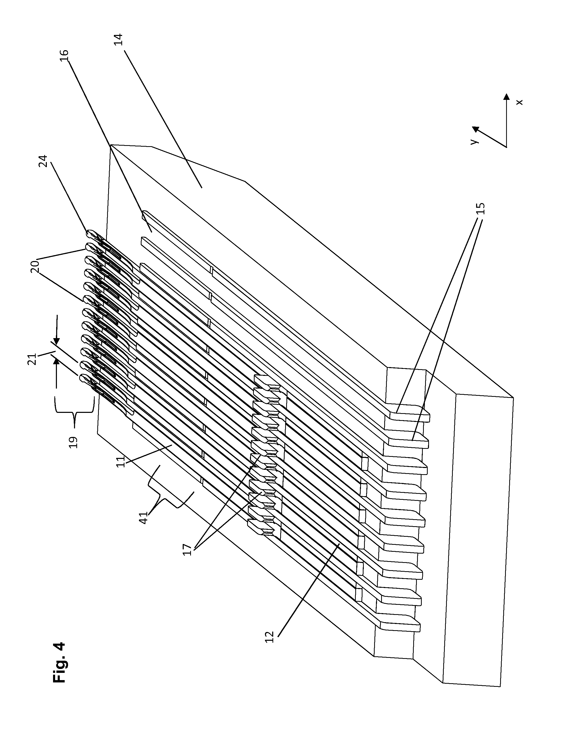
[0053] FIG. 4 shows a perspective view of a second needle bed which is equipped with first and second system components. The first system components are equipped with a spacer which adjusts the whole distance between the loop forming means of two adjacent system components of one groove.
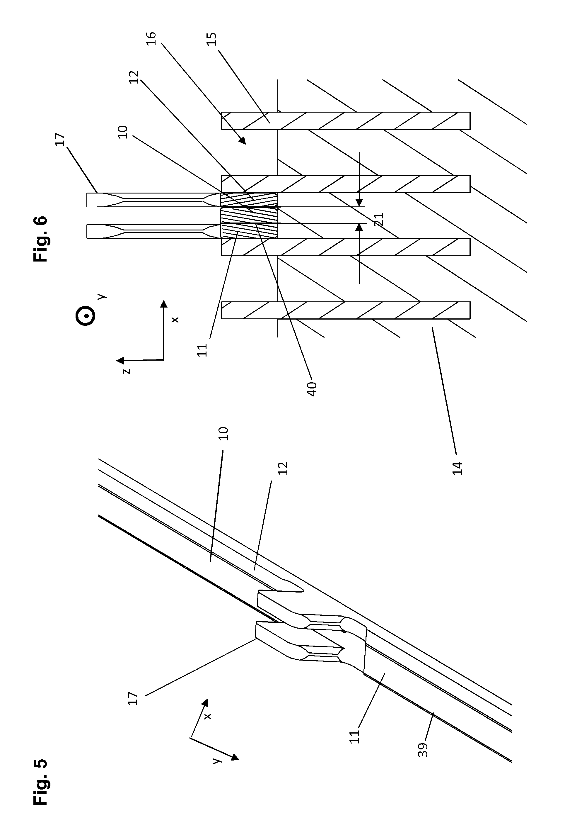
[0054] FIG. 5 shows a pair of two needles which were extracted from one groove of the second needle bed and which consist of a first needle with a spacer and a second needle without one.
[0055] FIG. 6 provides a cross-sectional view of the second needle bed with one pair of system components.
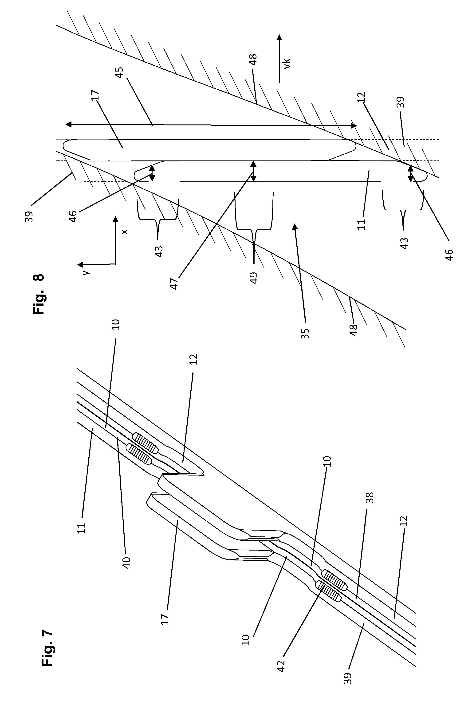
[0056] FIG. 7 shows a pair of needles consisting of two needles each one is provided with a spacer which is essentially an additional part.
[0057] FIG. 8 shows the passage of a cam with two butts of system components.
[0058] FIG. 9 provides a first symbolic arrangement of cams.
[0059] FIG. 10 shows a plain view of a third needle bed.
[0060] FIG. 11 is a plain view of a forth needle bed which is provided with a first and a second kind of system components with bends in its shanks.
[0061] FIG. 12 is a plain view of a fifth needle bed.
[0062] FIG. 13 provides a second symbolic arrangement of cams.
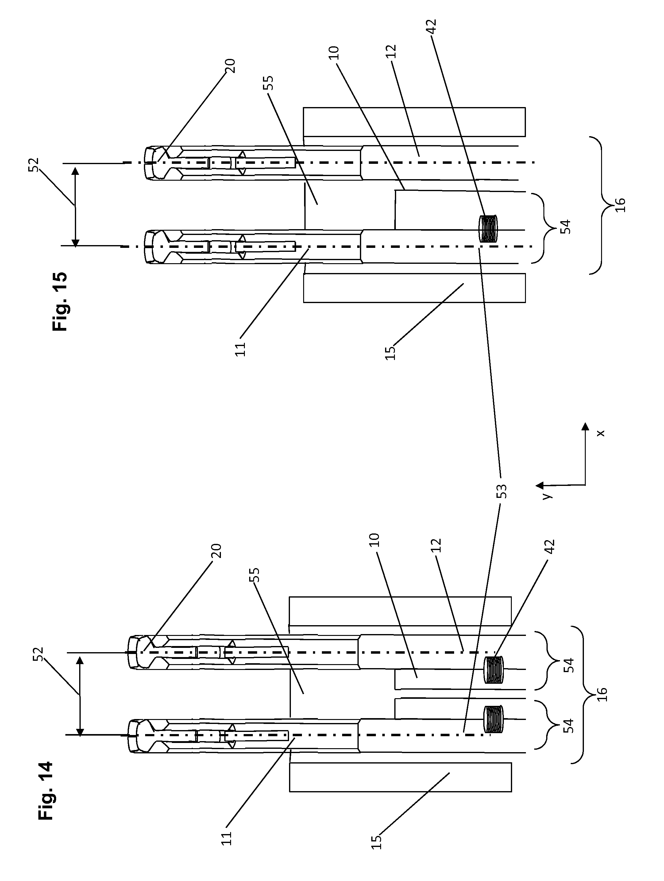
[0063] FIG. 14 provides a plain view of a first groove equipped with system elements
[0064] FIG. 15 provides a plain view of a second groove equipped with system elements
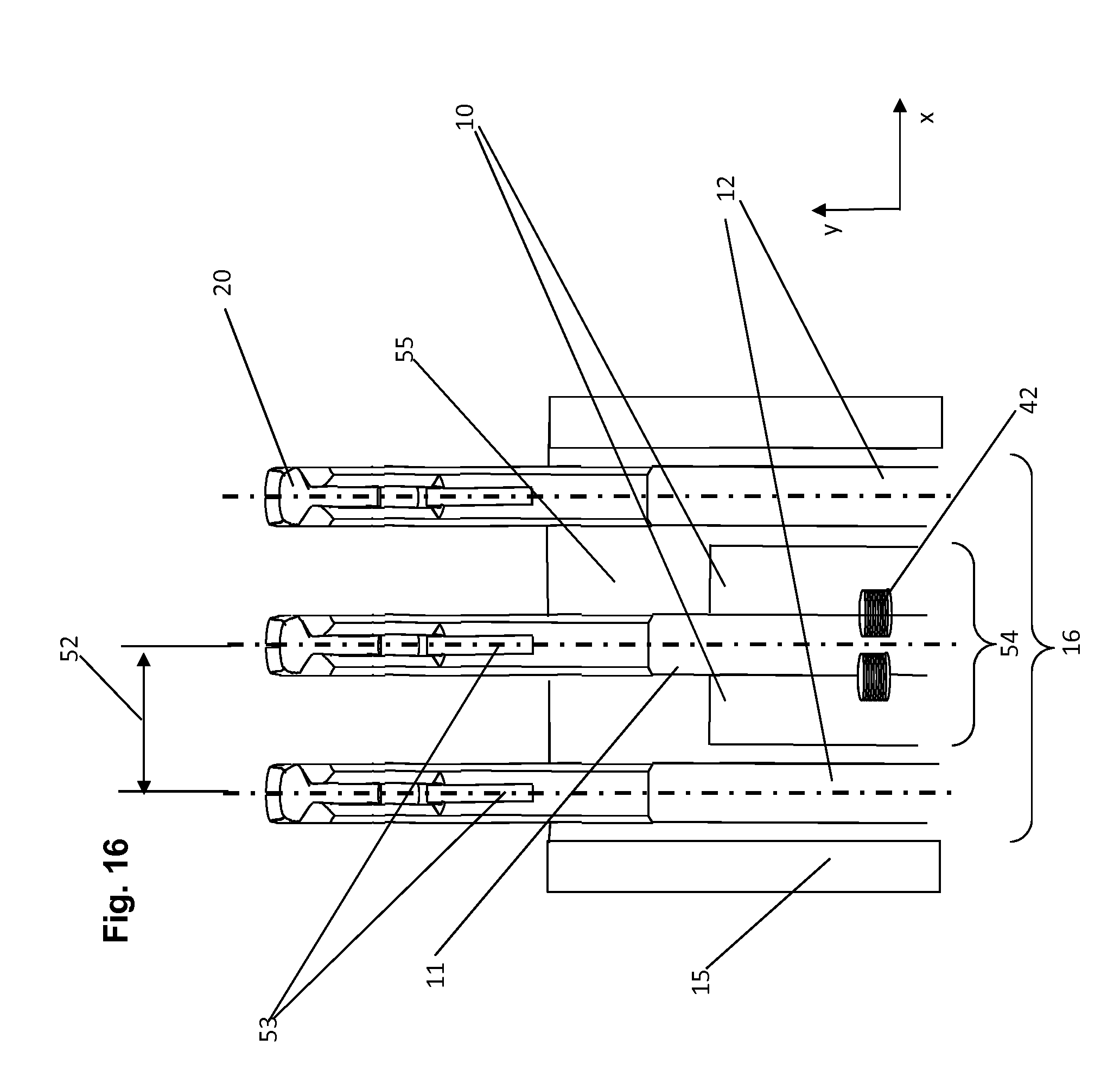
[0065] FIG. 16 provides a plain view of a third groove equipped with system elements
[0066] FIG. 1 shows a needle bed 14 which is provided with grooves 16 which are delimited by immovable walls 15. In the grooves 16 of this first embodiment of a needle bed 14 there are two system components 11 and 12. The power for the movement of the system components is transferred with butts 17 to the system components 11 and 12. Each system component 11, 12 is provided with loop forming means. In the case shown in FIG. 1 the system components 11 and 12 are latch needles and therefore their loop forming means are hooks 20 and latches 24, which extend in a loop forming zone 19. FIGS. 2 and 3 are about the same embodiment of the needle bed 14 and its system components 11, 12. FIG. 2 shows a system component 11 of the kind used in the needle bed 14 of FIG. 1. As said before the system component 11 is a needle with a butt 17 and a shank 39. The system component 11 is also provided with a spacer 10 with which it is immovably connected. In the case shown the spacer 10 and the shank 39 of the system component 11 are of one piece. FIG. 3 shows a section of the needle bed 14 of FIG. 1 in a cross-sectional view. In FIG. 3 the distance 21 which is also the distance between the loop forming means 20, 24 of two adjacent loop forming components 11, 12 of one groove 16 is clearly shown. The line 40 symbolizes the limitation between spacers 10 and shank 39 which does not really exist since these two members of the first embodiment are of one piece. In the first embodiment the first 11 and the second 12 system component are each provided with one spacer 10. These spacers 10 have the same width so that each of the spacers adjusts half of the distance 21. As already said before those spacers are of one piece with the shanks 39 of the system components 11, 12 with which they are immovably connected.
[0067] FIGS. 4, 5 and 6 show a second embodiment of the needle bed and its respective system components. The only significant difference between the first and the second embodiment shown in this publication is that in the second embodiment two adjacent system components 11, 12 of one groove 16 are only provided with one spacer 10 which is immovably connected with the first 11 of the two system components. This means that the whole distance 21 between the loop forming means 20, 24 of the two system components 11, 12 is adjusted only by means of only one spacer 10. This spacer 10 is once again of one piece with the system component with which it is connected. In both embodiments shown so far one can easily see that there are segments 41 of the longitudinal extension of the grooves 16 in which the spacers 10 are housed or moved. An arbitrary segment of the longitudinal extension of the grooves is symbolized by the bracket 41. In the first embodiment the two spacers 10 are in contact with each other when the system components 11, 12 are moved in the grooves 16. In the second embodiment only the first system component 11 is provided with a spacer 10 and the spacer 10 touches the second system component 12 when moved and even when the knitting machine does not work. The segments 41 of the grooves 16 in which this condition applies (the spacer 10 touches the adjacent system component 11) are very long (more than 90% of the system components' length.
[0068] FIG. 7 shows a pair of system components 11, 12 which is very similar to the pairs of system components 11, 12 which are housed in the grooves 16 of the first embodiment: Both system components 11, 12 are immovably connected with one respective spacer 10. Unlike the needles of the first embodiment the needles shown in FIG. 7 are not of one piece with their respective spacer 10. Therefore, this spacer 10 is an additional part 38 which is mated with the shank 39 of the respective system component 11, 12 with several weld points 42. Therefore the line 40 has in FIG. 7 a very physical significance since it denotes the limitation between two members 11, 10, or 12, 10. In most cases the joints or connections of very similar materials could be welt points or welt lines. Solder points or lines can mate similar or at least slightly different materials like different metals. In other cases very different materials can also be used and mated with other connections like splints or adhesives or the like. One possibility is to manufacture the shank 39 of the system component 11, 12 presumably of metal and use a material with a very low friction and/or self-lubricating properties like graphite or Teflon for the spacer 10.
[0069] The embodiments of the system components which are shown in FIGS. 1 to 3 (first embodiment) and the system components shown in FIG. 7 have a butt in common which has a width which is smaller than the combined (maximum) extension of its spacer 10 and its shaft 39 in the second direction (x). The same applies with regard to the first system components 11 according to the second embodiment which is shown in FIGS. 4 to 6. In contrast to the embodiment shown directly below the system components of FIGS. 1 to 7 have this smaller width in all sections of their whole longitudinal extension 45.
[0070] FIG. 8 shows two butts 17 of system components 11, 12 which pass through the passage 35 of a cam 18. The reason for the butts' 17 passing through the passage 35 is the relative movement vk (see the respective pointer in FIG. 8) between cam holder and cams on one side and the needle bed 14 (not shown in FIG. 8) and system components 11, 12 with their butts 17 on the other side. The cam 18 is not completely shown in FIG. 8. The limitations 48 of the passage 35 are however shown. They are surrounded by a hatching which symbolizes parts of the cam 18. The viewer of FIG. 8 can see the two butts 17 through the passage 35 (the cam holder is for the viewer transparent) so that invisible parts of the system components shanks (the parts covered by the cam) have to be shown with broken lines. Both butts 17 have an extension 45 in the first direction y. The width 46 of the butts 17 in the end sections 43 is smaller than their width 47 in their middle sections 49. This definition does not include end sections of state-of the art butts with rounded edges or edges which are in any other ways chamfered. The aforementioned feature (different widths in different sections, see above) is advantageous with regard to any embodiment of the present invention. It is however even more advantageous with regard to embodiments which are equipped with butts which have a maximum width in the second direction x which is bigger than the extension of the respective system component's 11, 12 loop forming means 20, 24. In this case, it is advantageous if there are end sections 43 of the butt 17 with a width which is equal to the width of the loop forming means 20, 24. It is even more advantageous if there are sections in the middle part which are provided with a width which is equal to the maximum width of the system component and the spacer combined (in x direction). In most cases the end sections will have a somewhat wedge-shaped end. The very end section of the butts 17 could be rounded.
[0071] FIG. 10 provides a plain view of a needle bed 14 which is equipped with system components 11, 12 which have the same butts which are shown in more detail in FIG. 8. Once again a pair of system components 11 and 12 is housed in one groove 16 which is delimited by immovable walls 15. The butts of the different system components are arranged with regard to each other as if they were passing a passage 35 of a cam 18 as the ones shown in FIG. 9.
[0072] FIG. 9 shows two cams 18. The second one is placed above the first one. Each of the cams 18 is provided with a passage 35 and a maximum 37. FIG. 13 also shows two cams being arranged above each other. The maxima 37 of the two cams 18 are displaced or shifted in the second direction x with regard to each other. This shift 50 is a very advantageous possibility to adjust the delay between adjacent system components which are therefore driven by different groups of cams 18 whereby each of the groups defines one cam track. Usually, the cams are fixed on a cam holder. Circular knitting machines usually have a cam holder which is fixed on the machine frame. Flat knitting machines are often provided with a carriage which performs a relative movement with regard to the needle bed. In most cases the "distance" 50 shall be a linear distance in flat-knitting machines and a distance which comprises circular components in circular knitting machines. There are additional benefits if this measure is used with regard to needles which are provided with butts 17 which have a width in the second direction x which is equal or nearly equal to the combined joint width of spacer 10 and system component 11, 12.
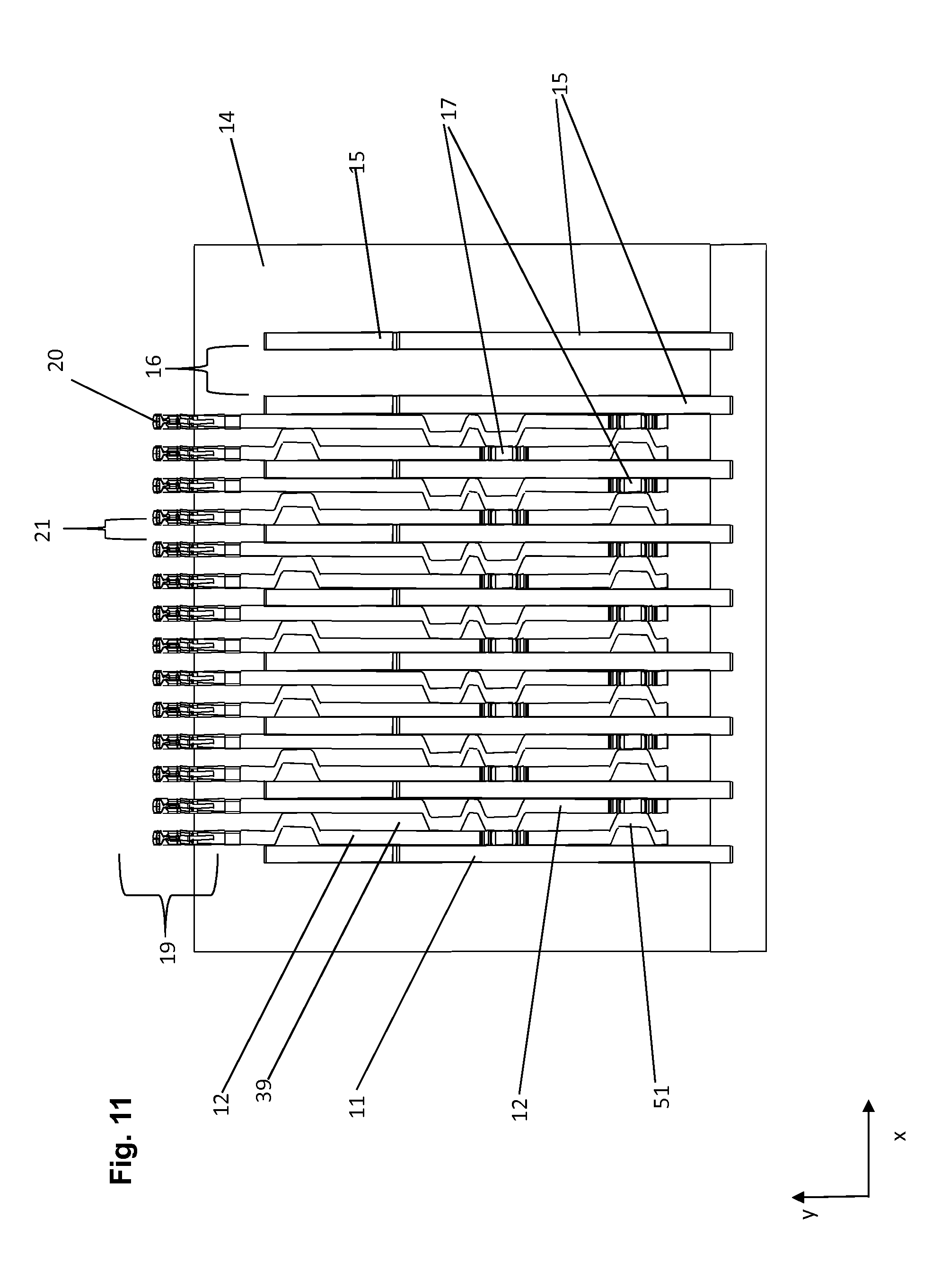
[0073] FIG. 11 once again shows a plain view of a third needle bed 14 in which pairs of system components 11, 12 are moved in one groove 16. The said grooves 16 are once again delimited by immovable walls 15. It is necessary to emphasize that the present invention has also its benefits with regard to needle beds which house 3, 4, 5, 6 or even more system components. The first system components 11 and the second system components 12 have their butts 17 in different longitudinal y positions. Hence the first and second system components 11, 12 are moved along different cam tracks. Most interestingly, the spacers 10 of the embodiment shown in FIG. 11 are bends 51 of the shanks of the respective system components 11, 12. The bends 51 of the first system components 11 are in contact with the shanks 39 of the second system components 12 and vice versa. Therefore, no bend 51 or spacer 10 (which are the same in this embodiment) touches another spacer's surface and all spacers touch another's system components side surface.
[0074] FIG. 12 shows a top view of a fifth needle bed 14. Needle beds of the kind shown in FIG. 12 are often used in circular knitting machines. In the case of circular knitting machines the needle bed 14 would also be called needle cylinder. FIG. 12 shows an example of a loop-forming process which takes place in the loop-forming zone 19. The needles 11, 12 and especially the hooks 20 and latches 24 take part in the loop forming process and therefore get in contact with the yarn 23. The sinkers 25 also get in contact with the yarn 23. The extension of the loops 33 in x-direction is symbolized by the brackets 33. FIG. 12 also shows some more details of the needles 11, 12 and the needle bed 14 which are well known to the man skilled in-the-art: The latches 24 are pivoted in the saw slot 26. During the loop forming process the latches 24 swing around the pivot 27 so that the interior of the hooks 20 is opened and closed for the yarn 23 by the latches 24. During the loop forming process the needles essentially move in the direction y of their shanks or of the grooves 16 of the needle bed 14. The sinkers 25 essentially move in the direction z of the height of the shanks of the needles 11, 12. The needle bed 14 is provided with slots 28 which look like teeth in the view provided by FIG. 12. The slots 28 guide the sinkers' 25 movements. The differences between the sinkers 25 and the spacers 10 can be summarized as follows:
[0075] The spacers 10 move together with the system components 11, 12. They are mated with them with splints 44 which are symbolized by the dotted lines 44. The spacers 10 are also devoid of loop forming means like hooks 20 and latches 24 and the like and do not take part in the loop-forming process. Moreover, the spacers essentially define the distance between two neighboring or adjacent system components 11, 12 and their loop-forming components 20, 24. Most of the time the sinkers 25 and the respective system components 11, 12 still have a certain distance, so that the distance between these system components 11, 12 is the sum of these distances and the sinkers' 25 width. The areas of the loop-forming zone 19 which are situated between the loop-forming means 20, 24 of the system components 20, 24 of the first needle bed 14 are free from loop forming means which are part of or actuated by loop forming means of this needle bed. The loop forming means of the sinkers 25 are part of the sinkers which are moved in the grooves of another needle bed. The grooves of individual needle beds 14 are usually parallel to each other.
[0076] Most advantageously the immovable walls 15 and/or the shanks 39 of the system components 11, 12 and/or the spacers 10 have the correct width corresponding with the gauge of the respective needle bed 14. In some advantageous embodiments the width of immovable walls 15 and/or the shanks 39 of the system components 11, 12 and/or the spacers 10 is (nearly) equal.
[0077] The above passages partly deal with the distance 21 between the loop forming means 11, 12 of one groove. In cases, in which a system component is provided with several loop-forming means--like the hooks 20 and latches 24--it is advantageous to say that the width of these loop forming means is equal with their broadest extension in the second direction x: As a result, the latch needles of FIG. 12 are provided with loop-forming means which have a width which is identical with the width of their hooks since the hooks 20 are broader than the latches 24.
[0078] On the other hand FIG. 12 also provides a different possibility to define the distance between adjacent loop-forming means: The numeral 52 (see pointer 52) denotes the distance between the centers of the hooks 20 of two adjacent system components. This distance 52 is (of cause) equal to the distance of two adjacent loops which are being formed by the respective hooks. The man-skilled-in-the-art often calls this distance "pitch" (the pitch denotes this distance in millimetres whereas the gauge is the number of needles per inch). In most loop-forming methods and also in most loop-forming devices this pitch is even (all system components of one needle bed have the same distance with regard to each other). Otherwise the knitted fabric produced by such a machine would be perceived as uneven by the consumer. With regard to the present invention one could also say that the spacer adjusts or helps to adjust the pitch between adjacent needles or system components.
[0079] FIG. 14 provides a plain view of the first groove 16 of the needle bed 14 which is equipped with system components 11, 12. Each of the system components 11, 12 is immovably connected with a spacer 10 by means of a weld point 42. Therefore one could also say, that the system component 11 and the spacer 10 with which it is immovably connected form a system unit 54. The same applies with regard to the other system component 12 and the respective spacer 10.
[0080] The line 53 is a symmetry line which is directed in the longitudinal direction y parallel to the side surfaces of the needles' shanks 39 and which crosses the centre of the needles' hook 20. FIG. 14 shows that the system component 11 is symmetrical with regard to the symmetry line 53. This figure also shows that the system unit 54 which moves together during the loop-forming process is not symmetrical with regard to the line 53. The same applies with regard to the system component 12 its spacer 10 and the unit 54 which is formed by the two aforementioned elements. FIG. 15 shows a slightly different excellent groove which is equipped with two system components 11, 12 and one spacer 10 which provides for the whole distance between the loop-forming means 20, 24 of the two adjacent system components 11, 12. The respective spacer 10 is immovably connected by a plurality of weld points 53 (only one weld point is shown by FIG. 15) with the system component 11 so that the system components 11 and the spacer 10 once again form a system unit 54 which is moved together during the loop forming process. The system component 11 is symmetrical with regard to symmetry line 53. Once again the unit 54 which is formed by the system components 11 and the spacer 10 is not symmetrical with regard to the aforementioned line 53. The system component 12 can be a standard needle which is symmetrical to the other line 53 which cuts the respective system component in two halfs. The embodiment shown in FIGS. 14 and 15 show that inventive embodiments are most of the time provided with system units which are not symmetrical with regard to symmetry line 53 which is parallel to the side surfaces of the respective system component 11, 12 and which crosses the centre of the hook 20. In this regard FIG. 16 shows an exceptional embodiment of a further groove 16 which is delimited by the immovable walls 15 and the bottom of the groove 55. The system component 11 which is placed in the middle of the groove and surrounded by two other system components 12 is immovably connected with two spacers 10 whereby each of the spacers 10 is placed on one of the system component's 11 two different side surfaces. Therefore the system component 11 and the two spacers 10 with which it is connected form another system unit 54. This system unit 54 is symmetrical with regard to the symmetry line 53. The same applies with regard to the other two system components 12 which can be stand-up needles. This is to say that the inventive embodiments shown in FIG. 16 can be equipped with system units (elements which form a unit which is moved together during the loop forming process) which are symmetrical with regard to the symmetry line 53. As mentioned above, the embodiments shown in FIGS. 14 and 15 are provided with at least one system unit which is not symmetrical with regard to the symmetry line 53. This feature is generally of benefit for inventive embodiments.
[0081] FIGS. 14, 15 and 16 elucidate another property of the invention. The grooves 16 are broader (possess a bigger width in the direction x) than state-of-the-art needle beds 14. Needle beds which are appropriate for the present invention have a width which is bigger 0,7 times the pitch 52, or even bigger than the pitch 52 are even bigger than 11/2 times the pitch 52. The grooves which are provided with the aforementioned pitch can have a length which equals 95, 90, 85, 80, 70 or 60% of the system components' length. The respective grooves are easy to clean and the oil consumption of the overall new device is smaller than in most state-of-the-art devices. The broad grooves or channels are cheap and easy to grind (especially if a small pitch is required).
TABLE-US-00001 List of numerals 10 Spacer/element 11 First Needle/element/system component 12 Second Needle/element/system component 14 Needle bed 15 Immovable wall which delimits two grooves of a needle bed 16 Groove/channel for guiding elements 17 Butt of the elements 18 Cams 19 Loop-forming zone 20 hook 21 Distance between the needles 11 and 12 23 Yarn/Thread 24 Latch 25 Sinker 26 Saw slot 27 Pivot of the latch 28 Tooth of the needle bed 33 Bracket signifying the extension of a loop 35 Passage for the butts 17 in the cam 18 37 Extrema of a passage 37 (in y-direction) 38 Additional part 39 Shank 40 Thick line which symbolizes the limitation between spacer and shank 41 Segments of the longitudinal extension of the grooves/Bracket signifying such a segment 42 weld point 43 End section of the butt (in the first direction y) 44 Splint, dotted line signifying such a splint 45 Extension of the butt in the first direction y 46 First width of the butt (end section) 47 Second width of the butt (Middle section) 48 Limitation of the passage 35 49 Middle section of the butt 50 Distance between the extreme are of two cams of a different contract 51 bends 51 of the shanks of the respective system components 52 Distance between the centre of two adjacent hooks or pitch 53 symmetry line 54 System unit comprising a system component und the spacer(s) with which it is connected 55 bottom of a groove x Direction of the width of the shanks of the elements/grooves y Direction of the length of the shanks of the elements/grooves z Direction of the height of the shanks of the elements/grooves vk First velocity/velocity of needle bed, relative velocity cam holder/needle bed
* * * * *
D00000
D00001
D00002
D00003
D00004
D00005
D00006
D00007
D00008
D00009
D00010
XML
uspto.report is an independent third-party trademark research tool that is not affiliated, endorsed, or sponsored by the United States Patent and Trademark Office (USPTO) or any other governmental organization. The information provided by uspto.report is based on publicly available data at the time of writing and is intended for informational purposes only.
While we strive to provide accurate and up-to-date information, we do not guarantee the accuracy, completeness, reliability, or suitability of the information displayed on this site. The use of this site is at your own risk. Any reliance you place on such information is therefore strictly at your own risk.
All official trademark data, including owner information, should be verified by visiting the official USPTO website at www.uspto.gov. This site is not intended to replace professional legal advice and should not be used as a substitute for consulting with a legal professional who is knowledgeable about trademark law.