Insulative Sleeve For Beverage Cup
Pimentel; Steven Niels ; et al.
U.S. patent application number 15/640554 was filed with the patent office on 2019-01-03 for insulative sleeve for beverage cup. The applicant listed for this patent is Peigen Jiang, Steven Niels Pimentel. Invention is credited to Peigen Jiang, Steven Niels Pimentel.
| Application Number | 20190002184 15/640554 |
| Document ID | / |
| Family ID | 64735243 |
| Filed Date | 2019-01-03 |
| United States Patent Application | 20190002184 |
| Kind Code | A1 |
| Pimentel; Steven Niels ; et al. | January 3, 2019 |
INSULATIVE SLEEVE FOR BEVERAGE CUP
Abstract
An insulative sleeve for a beverage cup is disclosed which includes a flexible insulative sheet having a first end and a second end, when the flexible insulative sheet being rolled into the insulative sleeve, the first and the second end being next to each other without overlapping, and a joinery strip having approximately the same length as the first end, approximately one half of the joinery strip removably engaging the first end and approximately another half of the joinery strip removably engaging the second end.
| Inventors: | Pimentel; Steven Niels; (Redmond, WA) ; Jiang; Peigen; (Sammamish, WA) | ||||||||||
| Applicant: |
|
||||||||||
|---|---|---|---|---|---|---|---|---|---|---|---|
| Family ID: | 64735243 | ||||||||||
| Appl. No.: | 15/640554 | ||||||||||
| Filed: | July 2, 2017 |
| Current U.S. Class: | 1/1 |
| Current CPC Class: | A47G 2023/0291 20130101; B65D 81/3879 20130101; A47G 23/0216 20130101 |
| International Class: | B65D 81/38 20060101 B65D081/38; A47G 23/02 20060101 A47G023/02 |
Claims
1. An insulative sleeve for a beverage cup comprising: a flexible insulative sheet having a first end and a second end, when the flexible insulative sheet being rolled into the insulative sleeve, the first and the second end being next to each other without overlapping; and a joinery strip having approximately the same length as the first end, approximately one half of the joinery strip removably engaging the first end and approximately another half of the joinery strip removably engaging the second end.
2. The insulative sleeve of claim 1, wherein the flexible insulative sheet is shaped like a hand fan when being flattened, so that the insulative sleeve is a tapered tube.
3. The insulative sleeve of claim 1, wherein the flexible insulative sheet is made of a foam rubber material.
4. The insulative sleeve of claim 3, wherein the flexible insulative sheet is laminated with a cloth.
5. The insulative sleeve of claim 1, wherein the joinery strip has a first and a second protruding member for engaging the first end and the second end, respectively.
6. The insulative sleeve of claim 5, wherein the first and second protruding member leans toward each other by a predetermined angle.
7. The insulative sleeve of claim 5, wherein the first and the second protruding members are round pegs for being tightly fit into round holes in the flexible insulative sheet positioned near the first and the second end, respectively.
8. The insulative sleeve of claim 7, wherein the round pegs have a bulged middle section.
9. The insulative sleeve of claim 7, wherein the joinery strip is made of a plastic material.
10. The insulative sleeve of claim 5, wherein the first and the second protruding members are blades for being inserted in cuts formed in the flexible insulative sheet near the first and the second end, respectively.
11. The insulative sleeve of claim 10, wherein the joinery sleeve is made of a sheet metal with the blades stamped thereout.
12. The insulative sleeve of claim 1, wherein the joinery strip substantially covers a seam formed by the first and the second end.
13. The insulative sleeve of claim 5, wherein the first and the second protruding member each has a concave space on top thereof, and the joinery strip further comprises a cover strip having a third and fourth protruding member fitting in the concave spaces in the first and the second protruding member, respectively, for removably attaching the cover strip to the first and the second protruding member.
14. The insulative sleeve of claim 1, wherein the joinery strip includes two substantially parallel plates joint by a part substantially perpendicular to the parallel plates, a first gap formed between the parallel plates to one side of the perpendicular part being capable of removably retaining the first end, and a gap formed between the parallel plates to the other side of the perpendicular part being capable of removably retaining the second end.
15. The insulative sleeve of claim 14, wherein the parallel plates have one or more spikes on surfaces facing the first and the second gap, respectively.
16. The insulative sleeve of claim 15, wherein the spikes incline toward a middle of the joinery strip.
17. The insulative sleeve of claim 15, wherein the spikes on opposite surfaces of the parallel plates are not aligned in a direction perpendicular to the parallel plates.
18. The insulative sleeve of claim 14, wherein the joinery strip is made of a plastic material.
Description
BACKGROUND
[0001] The present disclosure relates generally to insulative apparatus for beverage cups, and, more particularly, to an insulative sleeve that can be separated from a beverage cup.
[0002] Beverages, such as coke or fruit juices, are preferably consumed when being chilled. However, in parties, beverages are often served in thin, one-time-use plastic cups that lack insulative capability. Beverages poured in such plastic cups can quickly get warmed up in the environment. As such, it is desirable to provide an insulative sleeve for the plastic cups that is inexpensive and easy to use.
BRIEF DESCRIPTION OF THE DRAWING
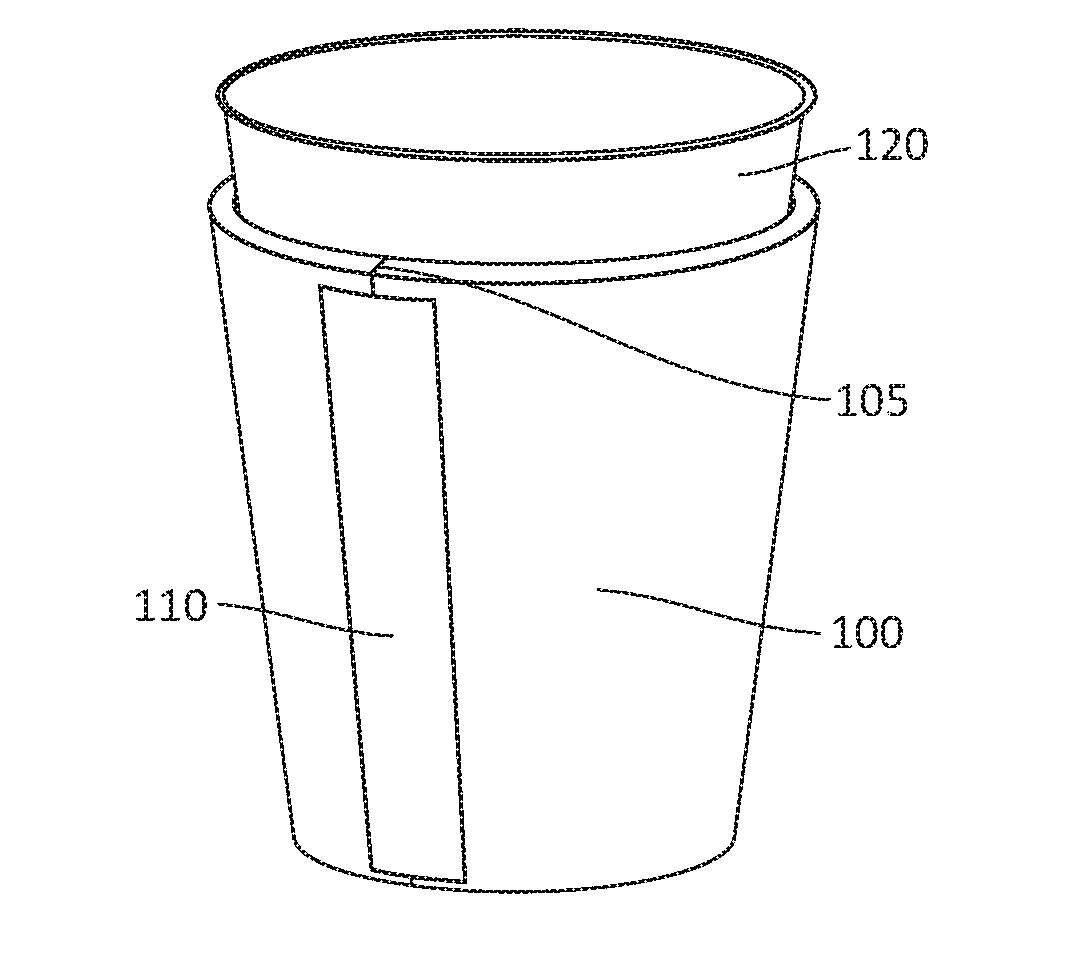
[0003] FIG. 1 illustrates an insulative sleeve according to an embodiment of the present disclosure that is wrapped around an exemplary beverage cup.
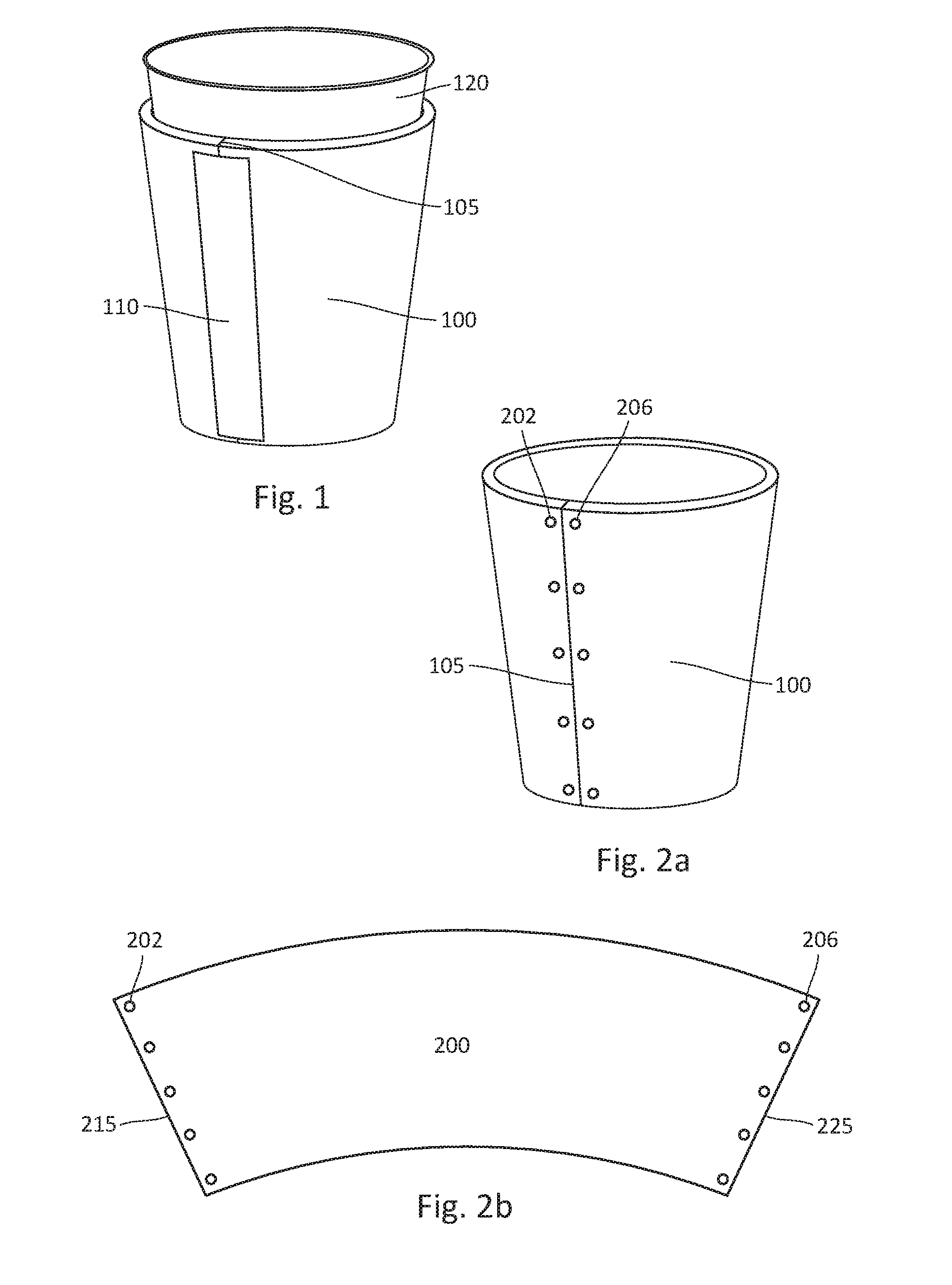
[0004] FIGS. 2a and 2b illustrate structure of the insulative sleeve shown in FIG. 1.
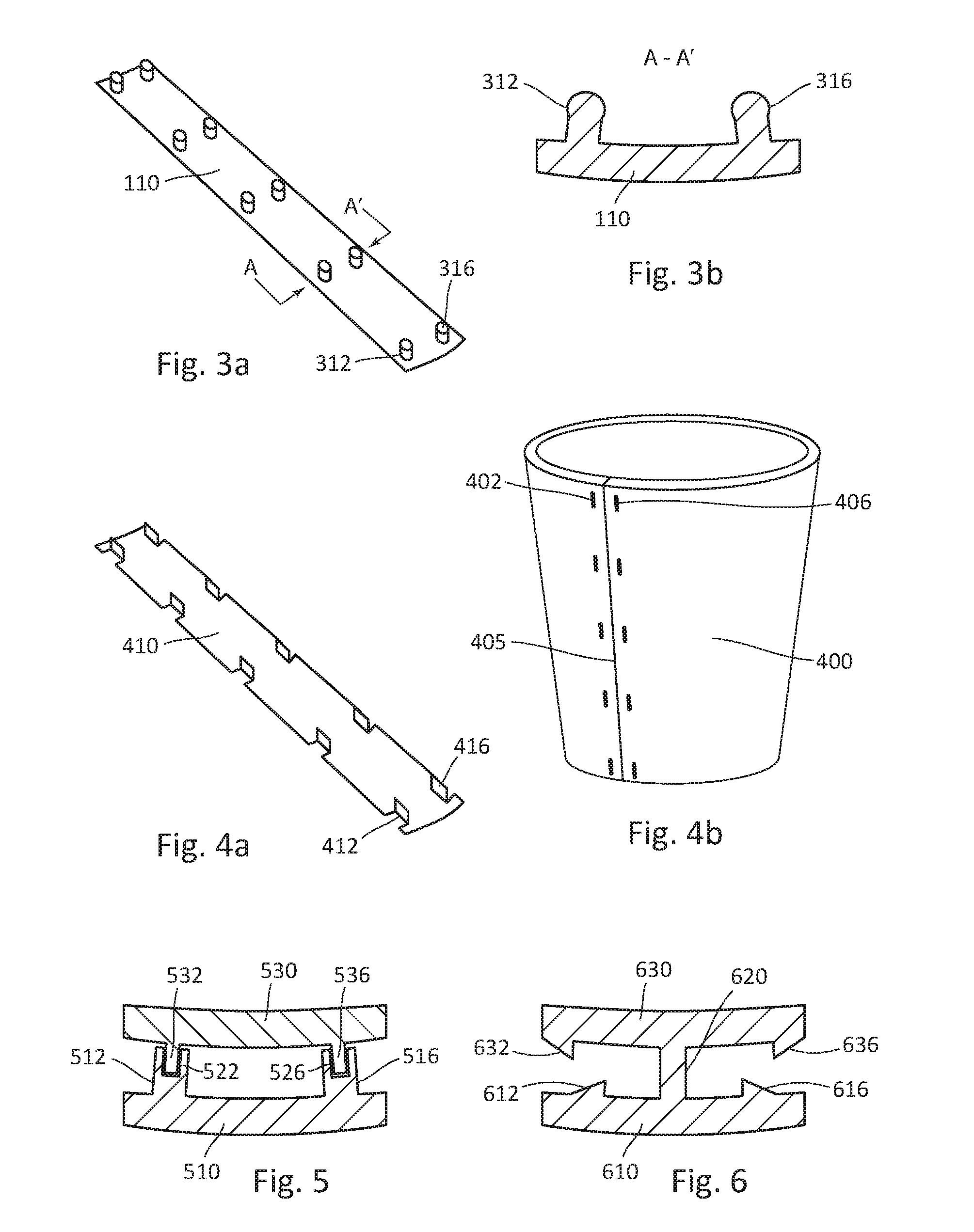
[0005] FIGS. 3a and 3b illustrate structure of a joinery strip for the insulative sleeve shown in FIG. 1.
[0006] FIGS. 4a and 4b illustrate an alternative joinery strip for an insulative sleeve according to an embodiment of the present disclosure.
[0007] FIG. 5 is a cross-sectional view of a joinery strip for an insulative sleeve according to an embodiment of the present disclosure.
[0008] FIG. 6 is a cross-sectional view of joinery strip for an insulative sleeve according to another embodiment of the present disclosure.
[0009] The drawings accompanying and forming part of this specification are included to depict certain aspects of the disclosure. A clearer conception of the disclosure, and of the components and operation of systems provided with the disclosure, will become more readily apparent by referring to the exemplary, and therefore non-limiting, embodiments illustrated in the drawings, wherein like reference numbers (if they occur in more than one view) designate the same elements. The disclosure may be better understood by reference to one or more of these drawings in combination with the description presented herein.
DESCRIPTION
[0010] The present disclosure relates to an insulative sleeve for beverage cups. A preferred embodiment of the present disclosure will be described hereinafter with reference to the attached drawings.
[0011] FIG. 1 illustrates an insulative sleeve 100 according to an embodiment of the present disclosure that is wrapped around an exemplary beverage cup 120. A typical example of such beverage cup 120 is a plastic cup that has a slightly tapered shape with top opening being larger than the bottom. The insulative sleeve 100 is shaped like a tapered tube press fit with the beverage cup 120, so that the insulative sleeve 100 serves as an insulation layer for the beverage cup 120. As shown in FIG. 1, a joinery strip 110 holds ends of the sheet together at a seam 105. In an embodiment, the insulative sleeve 100 is made of neoprene sponge foam rubber sheet rolled into a tapered tube. In another embodiment, the sheet material is laminated with a cloth (not shown) for esthetic purposes.
[0012] FIGS. 2a and 2b illustrate structure of the insulative sleeve 100 shown in FIG. 1. Referring to FIG. 2a, with the joinery strip 110 removed, punctured holes 202 and 206 are revealed. The hole 202 represents a group of holes punctured on the sheet to the left-hand side of the seam 105, while the hole 206 represents a group of holes punctured on the sheet to the right-hand side of the seam 105. The holes 202 and 206 are exemplarily placed close to each other and symmetrical to the seam 105. Although 5 holes are shown in FIG. 2a in each group of holes 202 and 206, an ordinary skilled in art would realize that more or less holes can be used as long as the joinery strip 110 can be retained by these holes when forming the insulative sleeve 100. In one embodiment, the holes 202 and 206 are punctured through holes. In another embodiment, especially when the thickness of the insulative sleeve is relatively thick, such as 10 millimeters, the holes 202 and 206 are just concave spaces without being punctured through.
[0013] Referring to FIG. 2b, when the insulative sleeve 100 is unrolled into a flat sheet 200, it is shaped like a hand fan with the group of holes 202 placed on one edge and the group of holes 206 on the other. A reason for such hand fan shape is because of the tapered shape of the insulative sleeve 100. If the insulative sleeve 100 is not tapered, the unrolled sheet 200 would be in a rectangular shape.
[0014] FIGS. 3a and 3b illustrate structure of a joinery strip 110 for the insulative sleeve 100 shown in FIG. 1. Referring to FIG. 3a, an inner surface of joinery strip 110 has two groups of protruding members 312 and 316, which are designed to be inserted in the holes 202 and 206, respectively, for joining the edges 215 and 225 of the sheet 200. As shown in FIGS. 2a and 2b, the holes 202 and 206 have a rounded opening, the protruding members 312 and 316, as shown in FIG. 3a, are also shaped like rounded pegs. In an embodiment, a uniform height of the protruding members 312 and 316 approximately equals to a uniform depth of the holes 202 and 206
[0015] Referring back to FIG. 1, an outer surface of the joinery strip 110 is smooth. However, ornamental features, such as textures or texts, may be embossed or printed on the outer surface instead.
[0016] FIG. 3b is a cross-sectional view of the joinery strip 110 at a location A-A'. As shown in FIG. 3b, both the inner and the outer surface of the joinery strip 110 have curved contours, that is because the surface of the beverage cup 120 shown in FIG. 1 is curved. As shown in FIG. 3b, in one embodiment, a top portion of the protruding member 312 or 316 is larger than a tip or bottom portion thereof to increase fiction with the holes 202 and 206 when the joinery strip 110 is engaged with the insulative sleeve 100. In another embodiment, the protruding members 312 and 316 lean slightly toward each other to pinch the holes 202 and 206 close together when the joinery strip 110 is engaged with the insulative sleeve 100.
[0017] FIGS. 4a and 4b illustrate an alternative joinery strip 410 for an insulative sleeve 400 according to an embodiment of the present disclosure. Referring to FIG. 4a, the joinery strip 410 is exemplarily made of a thin stainless-steel sheet with two groups of blade-like protruding members 412 and 416 stamped thereout. The protruding members 412 and 416 are substantially perpendicular to an inner surface of the joinery strip 410. Alternatively, the protruding members 412 and 416 can also slightly lean toward each other.
[0018] Referring to FIG. 4b, there are two groups of cuts 402 and 406 disposes on the insulative sleeve 400 along a seam 405 thereof. These cuts 402 and 406 are positioned so that the protruding members 412 and 416 of the joinery strip 410 fit in respective cuts 402 and 406 when being pressed into the insulative sleeve 400. Engagement of the protruding members 412 and 416 with the cuts 402 and 406 keeps ends of the insulative sheet material together to form the insulative sleeve 400.
[0019] FIG. 5 is a cross-sectional view of a joinery strip for an insulative sleeve according to an embodiment of the present disclosure. The joinery strip has two separate elongated parts 510 and 530. The bottom part 510 has two groups of protruding members 512 and 516. There is a concave space 522 disposed on top of each protruding member 512. Similarly, there a concave space 526 disposed on top of each protruding member 516. The top part 530 also have two groups of protruding members 532 and 536, which are sized and positioned to fit into the corresponding concave spaces 522 and 526, respectively. Fictions between the protruding members 532 and 536 and walls of the concave spaces 522 and 526 keeps the top part 530 attached to the bottom part 510, so that the insulative sleeve formed thereby is better secured between the top part 530 and the bottom part 510 comparing to the insulative sleeve 100 shown in FIG. 2a.
[0020] FIG. 6 is a cross-sectional view of joinery strip for an insulative sleeve according to another embodiment of the present disclosure. The joinery strip shown in FIG. 6 also has two horizontal parts 610 and 630 joint permanently by a vertical part 620 in the middle. To form a insulative sleeve, the edge 215 of an insulative sheet 200 shown in FIG. 2b can be squeezed in a space between the horizontal parts 610 and 630 to a left-hand side of the vertical part 620; while the edge 225 can be squeezed in a space between the horizontal parts 610 and 630 to a right-hand side of the vertical part 620. Although fictions between the sheet 200 and the horizontal parts 610 and 630 may be enough to keep the edges 215 and 225 in place, spikes 632 and 636 are exemplarily provided on an inner surface of the top horizontal part 630, and spikes 612 and 616 are exemplarily provided on an inner surface of the bottom horizontal part 610. As shown in FIG. 6, the spikes 612 and 632 are pointed inward so that the edge 215 is easier to be squeezed in than to be pull out. In an embodiment, tips of the spikes 612 and 632 are vertically misaligned, so that the edge 215 has a wider passage to be squeezed in. The spikes 616 and 636 are symmetrical to the spikes 612 and 632, respectively. Because the spikes 612, 616, 632 and 636, as well as the aforementioned protruding members should hold the edges of an insulative sheet in places, they must be made of a rigid material, such as plastic or metal.
[0021] While this disclosure has been particularly shown and described with references to exemplary embodiments thereof, it shall be understood by those skilled in the art that various changes in form and details may be made therein without departing from the spirit of the claimed embodiments.
* * * * *
D00000
D00001
D00002
XML
uspto.report is an independent third-party trademark research tool that is not affiliated, endorsed, or sponsored by the United States Patent and Trademark Office (USPTO) or any other governmental organization. The information provided by uspto.report is based on publicly available data at the time of writing and is intended for informational purposes only.
While we strive to provide accurate and up-to-date information, we do not guarantee the accuracy, completeness, reliability, or suitability of the information displayed on this site. The use of this site is at your own risk. Any reliance you place on such information is therefore strictly at your own risk.
All official trademark data, including owner information, should be verified by visiting the official USPTO website at www.uspto.gov. This site is not intended to replace professional legal advice and should not be used as a substitute for consulting with a legal professional who is knowledgeable about trademark law.