Fluid Delivery System Including A Disinfectant Device
Rodenbeck; Robert W. ; et al.
U.S. patent application number 16/064422 was filed with the patent office on 2019-01-03 for fluid delivery system including a disinfectant device. This patent application is currently assigned to Delta Faucet Company. The applicant listed for this patent is Delta Faucet Company. Invention is credited to Jayashanger Goundiah Ramasamy, Patrick B. Jonte, Garry R. Marty, John Noble, Robert W. Rodenbeck, Joel D. Sawaski, Anthony G. Spangler.
| Application Number | 20190001006 16/064422 |
| Document ID | / |
| Family ID | 59091174 |
| Filed Date | 2019-01-03 |


View All Diagrams
| United States Patent Application | 20190001006 |
| Kind Code | A1 |
| Rodenbeck; Robert W. ; et al. | January 3, 2019 |
FLUID DELIVERY SYSTEM INCLUDING A DISINFECTANT DEVICE
Abstract
A fluid delivery system illustratively includes a spout, at least one valve in fluid communication with the spout, and a disinfectant device, illustratively an antibacterial device, fluidly coupled to the spout. The faucet is configured to selectively flow water through the disinfectant device in response to a user input to the faucet. In another illustrative embodiment, the fluid delivery system includes an outer housing, a plurality of fluid devices supported by the outer housing, and an ozone generator fluidly coupled to the fluid devices.
| Inventors: | Rodenbeck; Robert W.; (Indianapolis, IN) ; Noble; John; (Carmel, IN) ; Spangler; Anthony G.; (Indianapolis, IN) ; Sawaski; Joel D.; (Indianapolis, IN) ; Goundiah Ramasamy; Jayashanger; (Fishers, IN) ; Jonte; Patrick B.; (Zionsville, IN) ; Marty; Garry R.; (Fishers, IN) | ||||||||||
| Applicant: |
|
||||||||||
|---|---|---|---|---|---|---|---|---|---|---|---|
| Assignee: | Delta Faucet Company Indianapolis IN |
||||||||||
| Family ID: | 59091174 | ||||||||||
| Appl. No.: | 16/064422 | ||||||||||
| Filed: | December 21, 2016 | ||||||||||
| PCT Filed: | December 21, 2016 | ||||||||||
| PCT NO: | PCT/US16/68081 | ||||||||||
| 371 Date: | June 20, 2018 |
Related U.S. Patent Documents
| Application Number | Filing Date | Patent Number | ||
|---|---|---|---|---|
| 62270395 | Dec 21, 2015 | |||
| Current U.S. Class: | 1/1 |
| Current CPC Class: | C02F 2201/4614 20130101; A61L 2202/14 20130101; A61L 2/18 20130101; A61L 2202/11 20130101; A61L 2/28 20130101; E03C 1/055 20130101; A61L 2/24 20130101; C02F 2209/40 20130101; C02F 2303/04 20130101; C01B 13/115 20130101; C02F 2209/04 20130101; C02F 2209/005 20130101; C02F 2209/02 20130101; C02F 1/78 20130101; F16K 37/00 20130101; C01B 2201/60 20130101; C02F 2307/06 20130101; A61L 2202/17 20130101; C02F 1/4672 20130101; A61L 2/0088 20130101 |
| International Class: | A61L 2/00 20060101 A61L002/00; A61L 2/24 20060101 A61L002/24; A61L 2/28 20060101 A61L002/28; C01B 13/11 20060101 C01B013/11; E03C 1/05 20060101 E03C001/05; F16K 37/00 20060101 F16K037/00 |
Claims
1. A faucet comprising: a spout including a waterway defining an outlet; at least one valve in fluid communication with the waterway of the spout; a controller in communication with the at least one valve; and a disinfectant device fluidly coupled to the waterway of the spout, the faucet being configured to selectively flow fluid through the disinfectant device in response to an input to the controller.
2. The faucet of claim 1, wherein the disinfectant device includes an antibacterial device.
3. The faucet of claim 2, wherein the antibacterial device includes an electrolytic ozone generator.
4. The faucet of claim 3, wherein the antibacterial device includes a first electrolytic ozone generator in serial fluid communication with a second electrolytic ozone generator.
5. The faucet of claim 3, wherein the ozone generator comprises: an outer cartridge; an electrolytic cell assembly received within the outer cartridge, the electrolytic cell assembly comprising: a first housing; an anode coupled to the first housing; a second housing a cathode coupled to the second housing; a separator positioned between the anode and the cathode; and a holder that couples the first housing to the second housing independently of the outer cartridge.
6. The faucet of claim 1, further comprising a sensor in communication with the controller and configured to detect a user's hands in proximity to the spout, the controller configured to determine hand washing compliance.
7. The faucet of claim 6, wherein the sensor includes an in-water sensor configured to detect a user's hands in a water stream delivered from the outlet of the spout.
8. The faucet of claim 7, wherein the in-water sensor is configured to detect a user's hands moving in the water stream delivered from the outlet of the spout.
9. The faucet of claim 7, wherein the in-water sensor includes a capacitive sensor.
10. The faucet of claim 1, further comprising a controller, and a sensor in communication with the controller and configured to detect the status of the antibacterial device.
11. The faucet of claim 1, further comprising a user interface in communication with the controller, the user interface including a time indicator configured to display a representation of the time water is discharged from the outlet of the spout.
12. The faucet of claim 11, wherein the time indicator includes a circular dial including a plurality of sectors that are selectively illuminated based upon the time that water is discharged from the outlet of the spout.
13. The faucet of claim 1, wherein the faucet is configured to selectively operate in a treatment mode and a non-treatment mode, where treated water passes through the disinfectant device in the treatment mode, and non-treated water by-passes the disinfectant device in the non-treatment mode.
14. The faucet of claim 13, wherein a light emitting device illuminates the water stream when the faucet is operating in the treatment mode.
15. The faucet of claim 1, further comprising a user interface in communication with the controller, the user interface including a compliance indicator configured to display a representation of a user's compliance with hand hygiene protocols.
16. The faucet of claim 15, wherein the compliance indicator provides a visual pass/fail indication of compliance with hand hygiene protocols.
17. The faucet of claim 1, further comprising a sensor configured to detect the amount of time that a user's hands are in a water stream discharged from the outlet of the spout.
18. The faucet of claim 17, wherein the controller is configured to provide an indication of the amount of time that the water stream is discharged from the outlet, and the amount of time that a user's hands are in the water stream.
19. The faucet of claim 18, wherein data regarding the amount of time that the a user's hands are in the water stream is stored in a remote database.
20. The faucet of claim 19, wherein the remote database is a cloud.
21. The faucet of claim 1, further comprising an identification device for determining the identity of a user.
22. The faucet of claim 21, wherein the identification device is a badge reader.
23. A water treatment dispensing system comprising: an outer housing defining a chamber; a first fluid device supported by the outer housing and fluidly coupled to a tap water source for delivering tap water to the hands of a user received within the chamber; and a second fluid device supported by the outer housing and fluidly coupled to an ozone generator for delivering ozonated water to the hands of a user received within the chamber, wherein the second fluid device comprises a fluidic chip configured to produce a fan of water within a plane by oscillating water about a center axis.
24. The water treatment dispensing system of claim 23, further comprising a gas mitigation system configured to draw ozone outgas from within the chamber, the gas mitigation system including a fan and a carbon filter operably coupled to the fan.
25. The water treatment dispensing system of claim 23, further comprising a user detector configured to activate water flow upon detecting the hands of a user within the chamber.
26. The water treatment dispensing system of claim 25, wherein the user detector comprises an electrode supported by the outer housing, and a capacitive sensor operably coupled to the electrode.
27. The water treatment dispensing system of claim 23, further comprising: at least one valve in fluid communication with the first fluid device and the second fluid device; a controller in communication with the at least one valve; a user interface in communication with the controller, the user interface including a compliance indicator configured to display a representation of a user's compliance with hand hygiene protocols.
28. The water treatment dispensing system of claim 23, wherein the fluidic chip is configured to produce a plurality of fans of water within diverging planes, the water oscillating within each of the planes about a center axis.
29. A water treatment dispensing system comprising: an outer housing defining a chamber; a plurality of fluid devices supported by the outer housing; an ozone generator fluidly coupled to the fluid devices for delivering ozonated water to the hands of a user received within the chamber; an electrically operable valve in fluid communication with the ozone generator for controlling fluid flow therethrough; a controller in electrical communication with the electrically operable valve; a user detector in electrical communication with the controller, wherein the controller controls the electrically operably valve in response to the user detector detecting the hands of a user within the chamber; and a gas mitigation system in electrical communication with the controller and including a fan configured to draw ozone outgas from within the chamber.
30. The water treatment dispensing system of claim 29, wherein the fluid devices comprise at least one a fluidic chip configured to produce a fan of water within a plane by oscillating water about a center axis.
31. The water treatment dispensing system of claim 30, wherein the fluid devices comprise at least one laminar flow device fluidly coupled to a tap water source for delivering tap water to the hands of a user received within the chamber.
32. The water treatment dispensing system of claim 29, wherein the gas mitigation system includes a carbon filter operably coupled to the fan and configured to treat the ozone outgas.
33. The water treatment dispensing system of claim 29, wherein the user detector comprises an electrode supported by the outer housing, and a capacitive sensor operably coupled to the electrode.
34. The water treatment dispensing system of claim 29, further comprising a user interface in communication with the controller, the user interface including a compliance indicator configured to display a representation of a user's compliance with hand hygiene protocols.
Description
CROSS-REFERENCE TO RELATED APPLICATION
[0001] The present application claims priority to U.S. Provisional Patent Application Ser. No. 62/270,395, filed Dec. 21, 2015, the disclosure of which is expressly incorporated herein by reference.
BACKGROUND AND SUMMARY OF THE DISCLOSURE
[0002] The present invention relates generally to an electronic faucet and, more particularly, to an electronic faucet including a water treatment device.
[0003] Fluid delivery devices, such as faucets, may include a fluid treatment device. For example, a treatment device may include a filter, an ozone device, and/or a water softener configured to treat the water before it flows from the faucet. A user input may be provided for controlled use of the fluid treatment device.
[0004] In one illustrative embodiment of the present disclosure, the treatment device may include a disinfectant device, such as an antibacterial device to inactivate bacteria and/or viruses that may be present in the fluid. The faucet may be used in a corporate, industrial, medical, and/or residential building to promote hand hygiene among those in the building. In this way, the faucet may be configured to provide feedback to the user or a monitoring system regarding each person's compliance with hand hygiene protocols based on the person's usage of the faucet. The faucet also may be configured to collect and report such usage and/or compliance information to the user and/or a monitoring system. In one illustrative embodiment, the faucet includes capacitive sensing technology to determine if a user's hands are within the flow stream of the faucet and can automatically turn the fluid and the fluid treatment device on and off, based on a user's presence near the faucet.
[0005] According to an illustrative embodiment of the present disclosure, a faucet includes a spout having a waterway defining an outlet, at least one valve in fluid communication with the waterway of the spout, a controller in communication with the at least one valve, and a disinfectant device fluidly coupled to the waterway of the spout. The faucet is configured to selectively flow fluid through the disinfectant device in response to an input to the controller. Illustratively, the disinfectant device may comprise an antibacterial device, such as an electrolytic ozone generator.
[0006] According to a further illustrative embodiment of the present disclosure, a water treatment dispensing system includes an outer housing defining a chamber, a first fluid device supported by the outer housing and fluidly coupled to a tap water source for delivering tap water to the hands of a user received within the chamber, and a second fluid device supported by the outer housing and fluidly coupled to an ozone generator for delivering ozonated water to the hands of a user received within the chamber. The second fluid device illustratively includes a fluidic chip configured to produce a fan of water within a plane by oscillating water about a center axis.
[0007] In another illustrative embodiment, a water treatment dispensing system includes an outer housing defining a chamber, and a plurality of fluid devices supported by the outer housing. An ozone generator is fluidly coupled to the fluid devices for delivering ozonated water to the hands of a user received within the chamber. An electrically operable valve is in fluid communication with the ozone generator for controlling fluid flow therethrough. A controller is in electrical communication with the electrically operable valve. A user detector is in electrical communication with the controller, wherein the controller controls the electrically operably valve in response to the user detector detecting the hands of a user within the chamber. A gas mitigation system in electrical communication with the controller and includes a fan configured to draw ozone outgas from within the chamber.
[0008] Additional features and advantages of the present invention will become apparent to those skilled in the art upon consideration of the following detailed description of the illustrative embodiment exemplifying the best mode of carrying out the invention as presently perceived.
BRIEF DESCRIPTION OF THE DRAWINGS
[0009] The detailed description of the drawings particularly refers to the accompanying figures in which:
[0010] FIG. 1 is a block diagram of an illustrative faucet of the present disclosure;
[0011] FIG. 2 is a further block diagram of the various components of the illustrative faucet of FIG. 1;
[0012] FIG. 3 is a perspective view of a spout supporting a user interface of the illustrative faucet of the present disclosure;
[0013] FIG. 4 is a front perspective view of the illustrative faucet of FIG. 3, showing the faucet in a first mode of operation;
[0014] FIG. 5 is a front perspective view of the illustrative faucet of FIG. 3, showing the faucet in a second mode of operation;
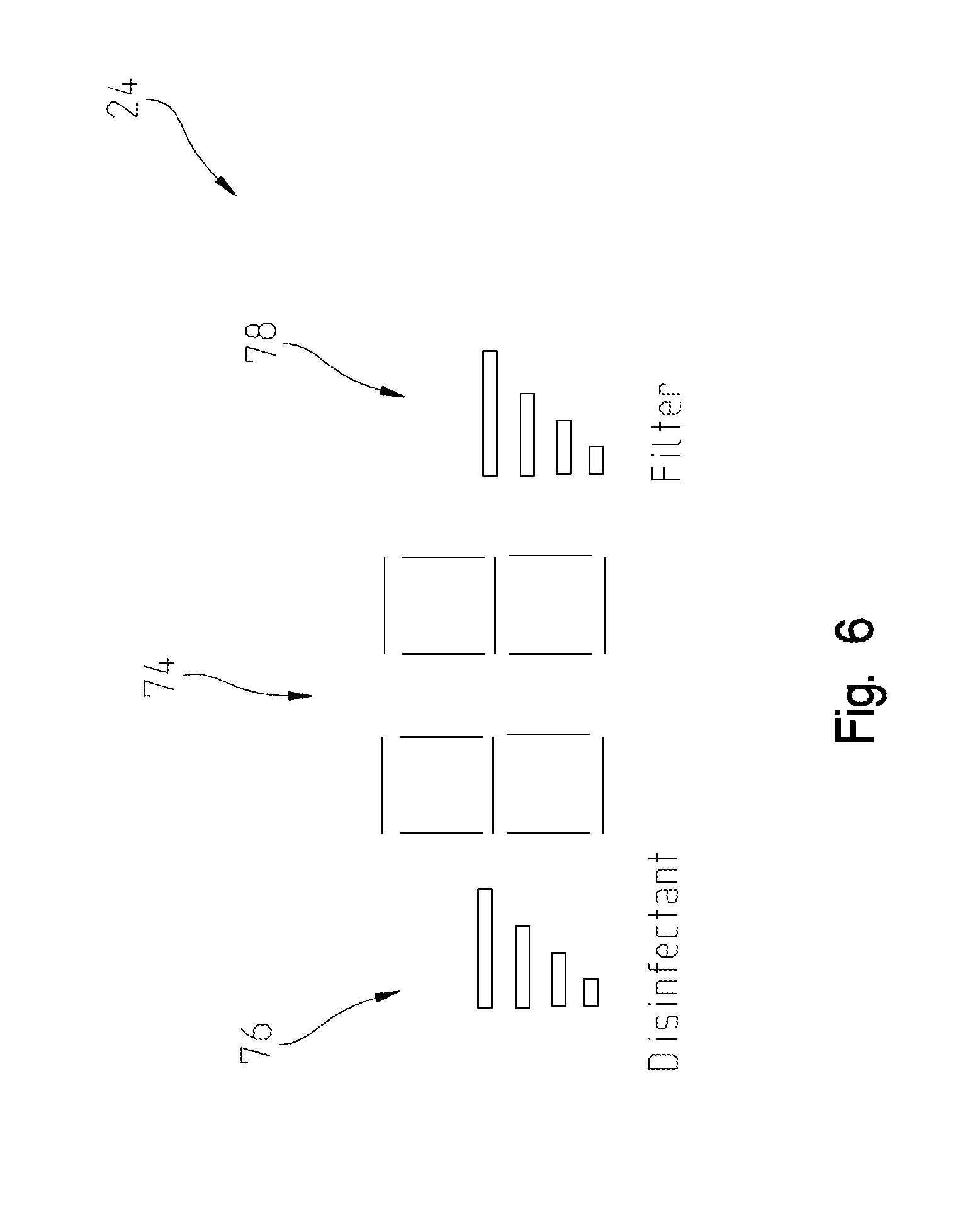
[0015] FIG. 6 is a schematic view of a user display for the illustrative faucet of FIG. 3;
[0016] FIG. 7 is a perspective view of an illustrative fluid dispensing system of the present disclosure, the fluid dispensing system including an outer housing having an opening to receive the hands of a user and an ozone off gas collector;
[0017] FIG. 8 is a cross-sectional view of the fluid dispensing system of FIG. 7, taken along line 8-8;
[0018] FIG. 9 is a cross-sectional view of the fluid dispensing system of FIG. 7, taken along line 9-9;
[0019] FIG. 10 is a perspective view in partial schematic of water dispensed by a two-dimensional fluidic device of the present disclosure;
[0020] FIG. 11 is a perspective view in partial schematic of the water dispensed by a three-dimensional fluidic device of the present disclosure;
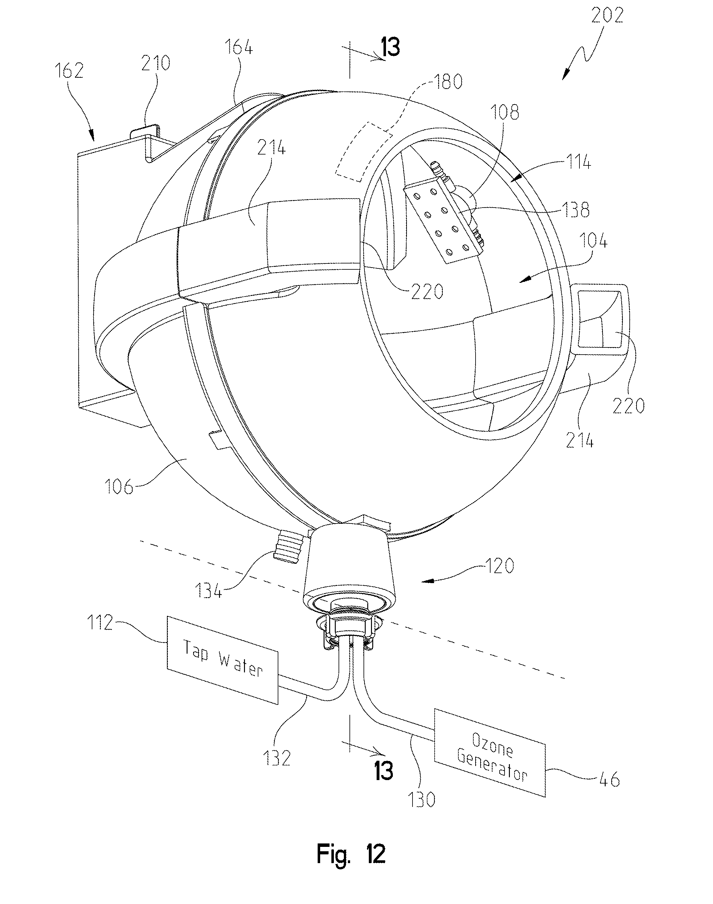
[0021] FIG. 12 is a perspective view of another illustrative fluid dispensing system of the present disclosure, the fluid dispensing system including an outer housing having an opening to receive the hands of a user and an ozone off gas collector;
[0022] FIG. 13 is a cross-sectional view of the fluid dispensing system of FIG. 12, taken along line 13-13;
[0023] FIG. 14 is a cross-sectional view of a further illustrative fluid dispensing system of the present disclosure; and
[0024] FIG. 15 is a perspective view of another illustrative fluid dispensing system of the present disclosure, the fluid dispensing system including a tap water faucet spout and an outer housing having an opening to receive the hands of a user.
DETAILED DESCRIPTION OF THE DRAWINGS
[0025] The embodiments of the invention described herein are not intended to be exhaustive or to limit the invention to precise forms disclosed. Rather, the embodiments selected for description have been chosen to enable one skilled in the art to practice the invention. Although the disclosure is described in connection with water, it should be understood that additional types of fluids may be used.
Water Treatment Faucet
[0026] Referring initially to FIG. 1, an illustrative embodiment water treatment fluid delivery device in the form of a faucet 10 is shown as including a delivery spout 12, a valve assembly 14, a waterway assembly 16, a filter 17, a fluid treatment assembly 18, a controller 20, a first sensor module 22, a user interface 24, and a second sensor module 26. Faucet 10 also may include a badge or identification (ID) reader 28 (FIG. 2), as disclosed further herein. In operation, valve assembly 14 of faucet 10 receives water from hot and/or cold water supplies 30 and 32 (e.g., conventional water stops) through input lines or tubes 34 and 36, and selectively mixes the incoming water to provide water to spout 12 through an outlet line or tube 38. Outlet tube 38 defines an outlet 39 supported by spout 12. In FIG. 1, hidden connector lines represent illustrative fluid flow paths, while solid connector lines represent illustrative electrical signal paths.
[0027] Faucet 10 may be mounted to a sink deck 40 or other suitable surface with spout 12 positioned to direct water from outlet 39 into a conventional sink basin or other area, for example. User interface 24 may be supported on spout 12 or adjacent thereto (e.g., on sink deck 40).
[0028] Spout 12 is illustratively coupled to a capacitive sensor 42 which is illustratively part of first sensor module 22 and is electrically coupled to controller 20. At least a portion of the spout 12 is illustratively formed of a metal defining an electrode electrically coupled to the capacitive sensor 42. The capacitive sensor 42 senses a change in its capacitive field caused by a human body. For example, the capacitive field may change when a user touches, grabs, or comes within a predetermined proximity to spout 12 (e.g., 1-5 inches). When a change is sensed that indicates the presence of a user near faucet 10, controller 20 may automatically activate valve assembly 14 to supply water to spout 12. Conversely, when the user is no longer near faucet 10, controller 20 may send a signal to valve assembly 14 to stop the flow of water to spout 12.
[0029] The fluid treatment assembly 18 illustratively includes a water treatment device and, more particularly, a disinfectant device such as an antibacterial device. As further detailed herein, the antibacterial device may include an electrolytic ozone generator or cell 46. The ozone generator 46 may include an outer cartridge and an electrolytic cell assembly received within the outer cartridge. The electrolytic cell assembly illustratively includes a first housing, an anode coupled to the first housing, a second housing, a cathode coupled to the second housing, a separator positioned between the anode and the cathode, and a holder that couples the first housing to the second housing independently of the outer cartridge. Illustrative ozone generators are further detailed in U.S. Patent Application Ser. No. 62/191,741, filed Jul. 13, 2015, entitled "ELECTRODE FOR AN OZONE GENERATOR" (Attorney Docket No.: DFC-4800-02-US-E), and U.S. Patent Application Ser. No. 62/254,667, filed Nov. 12, 2015, entitled "OZONE GENERATOR FOR A FAUCET" (Attorney Docket No.: DFC-4800-01-US-E), the complete disclosures of which are expressly incorporated by reference herein.
[0030] Sensor modules 22, 26 may include a plurality of sensors, such as flow rate sensors, pressure sensors, temperature sensors, ozone concentration sensors, current sensors, voltage sensors, capacitive sensors, and any other sensor that may be used with faucet 10 and supply information to controller 20. While the following description references oxidation-reduction potential sensors (ORP) as the illustrative ozone concentration sensors, it should be appreciated that other known sensors may be substituted therefor, including polarographic oxygen sensors.
[0031] Faucet 10 is illustratively configured for operation in at least two modes, including: a first or treatment mode (FIG. 4), and a second, non-treatment or tap water mode (FIG. 5). For example, when operating in the treatment mode, faucet 10 is configured to flow a fluid (e.g., water) through water treatment assembly 18 which disinfects at least a portion of the fluid flowing therethrough to provide fluid with antibacterial properties from spout 12. However, when operating in the non-treatment mode, fluid is configured to bypass water treatment assembly 18 such that fluid from waterway assembly 16, enters valve assembly 14, and is directed to spout 12. In an illustrative embodiment, the water may flow through filter 17 when faucet 10 operates in either the treatment mode or the non-treatment mode.
[0032] As shown in FIG. 2, in an illustrative embodiment, fluid treatment assembly 18 includes an ozone device 44 which may include at least one ozone cell or electrolytic ozone generator 46, an ozone controller 48, an ozone cell drive 49, an electrical relay 50, and at least one fluid treatment sensor, such as a flow rate sensor 52a and/or a temperature sensor 52b. Additionally, fluid treatment assembly 18 may include a solenoid valve 56. Illustratively, a pair of ozone cells 46a and 46b may be provided in parallel, wherein valve 56 may toggle water flow between the cells 46a and 46b. In another illustrative embodiment, the pair of ozone cells 46a and 46b may be provided in series fluid communication, wherein the controller 48 activates only a single ozone cell 46a, 46b is active at any given time. Alternatively or in addition to ozone generator 46, water treatment assembly 18 may include any device configured to treat fluid, e.g., a filter.
[0033] Illustratively, faucet 10 may be configured to monitor various consumable elements such as ozone cells 46a, 46b and filter 17. For example, usage of active ozone cell 46a may be monitored by minutes of usage and may be considered depleted at 100 hours of usage. When depleted, valve 56 may switch water flow from the first ozone cell 46a to the second ozone cell 46b. The user may then replace the first ozone cell 46a without causing interruption of the faucet 10.
[0034] Usage of filter 17 may also be monitored by gallons of fluid dispensed and/or overall hours of operation. For example, filter 17 may be considered depleted after 600 gallons of fluid and/or 600 hours of usage. Illustratively, a service switch may be provided to sense removal of the filter 17. Additionally, a pressure vent may be controlled via an electrical circuit to open a solenoid valve.
[0035] Information on the consumable elements of faucet 10 that may need to be periodically replaced, replaced, or updated may be uploaded to a server, computer, cloud, or any other device to monitor usage of such components. In one illustrative embodiment, the information on the consumable elements of faucet 10 is wirelessly communicated after every usage of faucet 10 to a cloud 58 (FIG. 2) via a wireless serial link.
[0036] Referring still to FIG. 2, valve assembly 14 of faucet 10 may include an electronic proportioning valve (EPV) 60 which controls flow rate and temperature of the water and also may be configured as an emergency shutoff valve. For example, a targeted temperature for the fluid output from spout 12 may be approximately 50-90.degree. F., and more particularly, 70.degree. F. when faucet 10 operates in the treatment mode. However, a targeted temperature for the fluid output from spout 12 may be approximately 90-115.degree. F., and more particularly 102-105.degree. F., when faucet 10 operates in the non-treatment mode.
[0037] When faucet 10 includes EPV 60, EPV 60 may include one or more shut-off features, which may provide a safety aspect to faucet 10. For example, if faucet 10 is used in a water system that requires two separate sub-systems (identified as ozone device 44 and water flow device 61 in FIG. 2) and required to operate simultaneously for faucet 10 to operate in the treatment mode, both sub-systems 44 and 61 monitor the parameters of the fluid (e.g., temperature, flow rate, pressure, ORP, and/or current) through sensors in first and/or second sensor modules 22, 26 and determine "agreement" between the readings on each sub-system. If there is disagreement in any reading between the two sub-systems, EPV 60 is configured to stop or shut down operation of faucet 10 such that faucet 10 stops dispensing fluid.
[0038] An additional safety feature may be provided by the faucet 10 monitoring the flow rate by flow rate sensor 52a. When the flow rate is active, the controller 48 monitors the levels of ozone from the ORP sensor 54 downstream from the ozone cell 46 (alone over time, or compared to a second ORP sensor 54 upstream from the ozone cell 46). If the ORP level is below a set level, then the controller 48 cuts power to the ozone cell 46 and disables flow by solenoid valve 56. The controller 48 then runs a diagnostics check and recycles power. The controller 48 illustratively attempts several reboots of the water treatment assembly 18 before locking it for maintenance, during which a maintenance code is displayed on the user interface 24.
Treatment Mode
[0039] With reference to FIGS. 3-5, during operation of faucet 10, the treatment mode may be set as a default mode such that faucet 10 initially operates in the treatment mode unless the user provides an input indicative of a desire to operate in the non-treatment mode. Alternatively, faucet 10 may operate in the treatment mode only when the user expressly specifies that the treatment mode should be used. For example, the user may input the treatment mode to user interface 24 which sends a signal to controller 20 to activate fluid treatment assembly 18. In this way, fluid from valve assembly 14 is directed through fluid treatment assembly 18 and, more particularly, through ozone device 44, to disinfect at least a portion of the fluid flowing to spout 12.
[0040] A light (e.g., LED) or other illumination device (not shown) may be positioned at, on, or near outlet 39 of spout 12 to illuminate the water flowing therefrom when faucet 10 operates in the treatment mode. In this way, the light indicates to the user that faucet 10 is in the treatment mode. Alternatively, spout 12 and/or user interface 24 may provide a visual indicator (e.g., words, graphics, colors, or sounds) that faucet 10 is in the treatment mode. For example, an ozone mode indicator 62 of the user interface 24 may be illuminated when the faucet 10 is operating in the ozone mode.
[0041] Fluid treatment assembly 18 may be configured to operate for a predetermined length of time before automatically turning off. For example, fluid treatment assembly 18 may operator for a minimum of 30 seconds before turning off and no longer disinfecting the fluid. After the predetermined length of time, valve assembly 14 also may automatically close to stop the flow of fluid to spout 12. Alternatively, valve assembly 14 may remain open to allow a continuous flow of fluid to spout 12 until the user turns off the fluid, however, the fluid may no longer be disinfected after operation of fluid treatment assembly 18. In such circumstances, the light or visual indicator 62 on spout 12 also may turn off to indicate to the user that the fluid is no longer disinfected.
[0042] During the treatment mode, controller 20 sends a serial command to ozone controller 48 to begin generating ozone. Ozone controller 48 enables ozone solenoid valve 56, and outputs a voltage to ozone cell(s) 46 (e.g., tri-oxygen cells) with a current of 0.8-2.0 Amps and, more particularly, a current of 1.2 Amps. Illustratively, the voltage and current to ozone cells 46 are reversed in periodic intervals (e.g., every 20 seconds) to prevent lime build up and keep the electrodes (not shown) within ozone cells 46 clean. The level of current may be adjusted based on the temperature of the water as sensed by temperature sensor 52b. Additionally, depending on the oxidation-reduction potential (ORP) of the water as sensed by ORP sensor 54, the current to the ozone cells 46 may be adjusted. Illustratively, ORP sensors 54 may be provided upstream and downstream from the ozone cells 46 to indicate that ozone is being generated. Current draw of ozone cell 46 indicates relative level of ozone. Finally, ozone gas resulting from outgassing may be collected and destroyed.
[0043] Ozone controller 48 also tracks usage and performance level of ozone cells 46. Illustratively, the ozone cells 46 are configured to reduce bacteria and viruses by 2 log or greater by providing an ozone concentration of 0.5 ppm at 0.5 gpm (efficacy determination). When a cell 46 is depleted, ozone controller 48 may operate other ozone cells 46 and/or provide a signal to controller 20 indicative of the depleted ozone cell 46. In this way, controller 20 may provide an output to the user via user interface 24 and/or to the monitoring system for faucet 10 that one of ozone cells 46 is depleted and may be replaced.
[0044] During illustrative operation of faucet 10 in the treatment mode, controller 20 provides an output to user interface 24 to show the elapsed time of operation for fluid treatment assembly 18 and/or a particular user's level of compliance with hand hygiene protocols. For example, user interface 24 may include a time indicator, such as a count-down or count-up timer or clock 64 (numeric or graphical) for the run time of ozone device 44, time that water is discharged from the outlet 39 of spout 12, and/or time that a user's hands are in the water stream discharged from the outlet 39 of spout 12. Illustratively, the clock 64 includes a dial including a plurality of sectors that are selectively illuminated in response to run time of the ozone device 44. For example, sectors 65a, 65b, 65c, etc. of the clock 64 may initially all be illuminated and then selectively turned off as time progresses (FIG. 3).
[0045] Compliance with hand hygiene protocols may be measured by the capacitive sensor 42 determining that the user's hands are placed and/or moving in the water stream discharged from spout outlet 39 for a period of time. This can be sensed by an absolute shift in measured capacitance (e.g., placement of hands in the water stream) or relative and random signal changes in the capacitive signal (e.g., movement of hands in the water stream) indicative of hand washing activity.
[0046] Additional details of capacitive sensing, including sensing a user's hands in a water steam of a faucet, are further detailed in U.S. Pat. No. 8,118,240, entitled "PULL-OUT WAND", U.S. Pat. No. 9,187,884, entitled "FAUCET INCLUDING A CAPACITANCE BASED SENSOR", and U.S. Patent Application Publication No. 2016/0177550, entitled "FAUCET INCLUDING CAPACITIVE SENSORS FOR HANDS FREE FLUID FLOW CONTROL", the complete disclosures of which are expressly incorporated by reference herein.
[0047] User interface 24 may also include a compliance indicator 66. More particularly, the compliance indicator 66 illustratively shows incremental increases by illuminating various sections 67a, 67b, 67c, etc. of the indicator 66, and/or by moving an pointer 69 along the indicator 66, while a user's hands are in the fluid stream, showing progress and encouraging the user to complete the disinfectant cycle (e.g., the predetermined 30-second cycle that ozone device 44 automatically operates, as disclosed herein).
[0048] Another indicator may be displayed on user interface 24 if the user's hands remained within the fluid stream during the complete operation cycle of ozone device 44. For example, a pass or "reward" indicator 71 (e.g., a green "thumbs up") may be displayed if full compliance is achieved, while a fail indicator 73 (e.g., a red "thumbs down") may be displayed in full compliance is not achieved (FIG. 3). If the designated timeout occurs such that ozone device 44 stops operating or full compliance by the user is achieved, solenoid valve 56 turns off to stop operation of ozone device 44 and the level of compliance is displayed on user interface 24.
[0049] Controller 20 also monitors the output of the sensors comprising first and/or second sensor modules 22, 26. More particularly, when fluid flows through valve assembly 14, EPV 60 may continuously adjust the hot/cold fluids to mix the water in a manner to reach a targeted temperature (e.g., 70.degree. F. during treatment mode). Additionally, controller 20 monitors the output from the ORP sensor 54 and ensures that the output is within pre-defined parameters. If the output from the ORP sensor 54 is not within the predefined parameters while in the treatment mode, EPV 60 may turn off water flow by closing valve assembly 14 and controller 20 sends a signal to stop operation of ozone cell(s) 46 via electrical relay 50.
[0050] At the end of every use of faucet 10, the compliance data may be uploaded to a monitoring system or device for faucet 10, which may be a computer, server, the "cloud," or any other data device configured to receive information from controller 20. In one embodiment, the compliance data is provided to the monitoring system through a wireless link to the "cloud." If faucet 10 is in a medical facility (e.g., a hospital), the compliance data may be wirelessly transmitted to the monitoring system or device through the medical facility's wireless internet. The compliance data includes a unit ID or badge ID, location, usage time stamp, compliance level (e.g., percentage of time the user's hands were within the fluid stream), and any other data related to maintenance and/or operation of faucet 10. Quality control personnel can access this data to run reports for this location or a grouping of faucets 10.
[0051] In one illustrative embodiment, as shown in FIG. 2, the user may be required to scan or otherwise provide identification information through badge reader 28 before faucet 10 will operate in either the treatment mode and/or the non-treatment mode. For example, if faucet 10 is in a medical facility, the user may be required to scan or otherwise provide employee ID information to badge reader 28 to allow faucet 10 to monitor the user's compliance with hand hygiene protocols during operation of faucet 10.
Non-Treatment Mode
[0052] With reference to FIGS. 2 and 4, a user may provide an input to the faucet 10 indicative of a desire to operate in the non-treatment or tap water mode. In one illustrative embodiment, when a user wishes to wash his or her hands using traditional tap water, the user may activate a conventional sensor (such as an infrared (IR), potentiometer, membrane switch, 2.sup.nd capacitive sensor, foot pedal, etc.). This sensor is monitored by the primary controller 20 to send a command to the ozone controller 48 to turn on a tap water solenoid valve 68. When the solenoid valve 68 is open, water flows through a bypass line 70. Once water flow begins, the primary controller 20 will adjust the EPV 60 to deliver 102-105.degree. F. water temperature to the spout 12. The primary controller 20 may illustratively display a hand washing signal on user interface 24 to use soap, and also monitor hands in the water stream, giving an indication for appropriate length and compliance level on user interface 24.
[0053] As in the treatment mode, water may be turned off at a preset time or when hands are absent for a set period of time (3-5 seconds). This information may also be illustratively uploaded to the cloud at the end of every usage. Spout 12 and/or user interface 24 may provide a visual indicator (e.g., words, graphics, colors, or sounds) that faucet 10 is in the non-treatment or tap water mode. For example, a tap water mode indicator 72 of the user interface 24 may be illuminated when the faucet 10 is operating in the non-treatment or tap water mode.
[0054] Also as in the treatment mode, during illustrative operation of faucet 10 in the non-treatment mode, controller 20 provides an output to user interface 24 to show the elapsed time of operation and/or a particular user's level of compliance with hand hygiene protocols. For example, user interface 24 may include count-down or count-up timer or clock 64 (numeric or graphical) for the time during which the valve 68 is open thereby causing tap water to flow through bypass line 70 to outlet 39 of spout 12, and/or time that a user's hands are in the water stream discharged from the outlet 39 of spout 12. Compliance with hand hygiene protocols may be measured by the capacitive sensor 42 determining that the user's hands are placed in the water stream discharged from spout outlet 39 for a period of time. This can be sensed by an absolute shift in measured capacitance (e.g., placement of hands in the water stream) or relative and random signal changes in the capacitive signal (e.g., movement of hands in the water stream) indicative of hand washing activity.
[0055] The compliance indicator 66 illustratively shows incremental increases while a user's hands are in the water stream, showing progress and encouraging the user to complete the hand washing cycle (e.g., a predetermined 30-second). Another indicator may be displayed on user interface 24 if the user's hands remained within the water stream during the complete operation cycle. For example, a "reward" indicator may be displayed if full compliance is achieved, while a fail indicator may be displayed in full compliance is not achieved.
[0056] With reference to FIG. 6, additional details of a further illustrative user interface 24 are shown. The user interface 24 may include a digital indicator 74 that provides an indication of time (such as clock 64 detailed above, but in a numeric form), and/or of operation or maintenance conditions of the faucet 10. For example, the indicator 74 may display error codes associated with the faucet 10. A first or O3 graphical indicator 76 may provide an indication of the remaining life expectancy of the active ozone cell 46, while a second or filter indicator 78 may provide an indication of the remaining life expectancy of the filter 17.
[0057] The illustrative faucet 10 provides improved hand hygiene by dispensing alternately tap water and ozone infused water that inactivates bacteria and viruses on contact, providing feedback to the user regarding their level of compliance to hand hygiene protocol through an interface supported on the spout (or mounted nearby), utilizing capacitive sensing technology to discern when hands are in the water stream, collecting and reporting usage and compliance information for quality control and improvement, and collecting and destroying ozone gas due to outgassing. As an added safety feature, the faucet 10 illustratively requires that two separate sub-systems function properly to dispense ozone water. Finally, the faucet 10 uses ozone to disinfect hands, uses capacitance sensing to know when hands are in the water stream for compliance reporting, integrates user compliance feedback into the spout, and provides real-time compliance reporting.
[0058] Additional features of illustrative faucet 10 may be disclosed in U.S. Patent Application Publication No. 2014/0352799, entitled "OZONE DISTRIBUTION IN A FAUCET", and PCT International Patent Publication No. WO 2013/086217, entitled "OZONE DISTRIBUTION IN A FAUCET", the complete disclosures of which are expressly incorporated by reference herein.
Water Treatment Dispensing System
[0059] With reference to FIGS. 7-9, an illustrative water treatment dispensing system 100 includes an ozone rinsing station 102 including a spherical chamber 104 defined by an outer housing or shell 106. While the outer housing 106 and the internal chamber 104 are illustrated as being spherical, other shapes may be substituted therefore.
[0060] A plurality of first fluid device couplers or holders 108 are supported by the outer housing 106 within the chamber 104 and operably coupled to the ozone generator 46 for distributing ozone infused (i.e., ozonated) water. A plurality of second fluid device couplers or holders 110 are supported by the outer housing 106 within the chamber 104 and operably coupled to a tap water source 112 for distributing untreated tap water. The holders 108 and 110 are arranged on an inner surface of the outer housing 106 in a manner to spray ozone infused (ozonated) water evenly on a user's hands when placed within the internal chamber 104.
[0061] The outer housing 106 may be formed of a polymer and includes an opening 114 to receive the hands of a user. An oval shield 116 may extend outwardly from the outer housing 106 and surrounds the opening 114. While the opening 114 may be of a variety of shapes and sizes, it is illustratively formed as an elongated slot in order to help prevent the release of outgassing of ozone from within the chamber 104.
[0062] A mounting assembly 120 is configured to couple the outer housing 106 to a mounting surface, such as sink deck 40. The mounting assembly 120 includes a shank body 122 coupled to a threaded bushing or sleeve 124 extending downwardly from the outer housing 106 via a first nut 126. In turn, the shank body 122 is coupled to the sink deck 40 by a second nut 128. An ozone water supply tube 130 illustratively extends through the shank body 122 and fluidly couples the ozone generator 46 with the first fluid device holders 108. A tap water supply tube 132 illustratively extends through the shank body 122 and fluidly couples the tap water source 112 with the second fluid device holders 110. A drain bushing or fitting 134 extends downwardly from the outer housing 106 adjacent to the sleeve 124 and is configured to fluidly couple with a drain tube (not shown) for removing waste water.
[0063] Each of the first fluid device holders 108 illustratively supports a first fluid device, illustratively configured to deliver ozonated water in a substantially laminar flow to reduce the potential of ozone outgassing. An illustrative first fluid device includes a conventional stream straightener 136 (e.g., an aerator) and/or a conventional spray head 138 (e.g., a rain can). Other fluid devices may be substituted therefore, including laminar flow blades.
[0064] Each of the second fluid device holders 110 illustratively supports a second fluid device for delivering an impacting spray providing a physical removal force to assist in removing bacteria and viruses. The disclosed arrangement of first and second fluid devices combine the benefits of physical removal force of tap water with the sanitizing effects of ozone to provide an effective and fast hand cleaning process.
[0065] An illustrative second fluid device includes a conventional spray nozzle or a conventional fluidic chip 140. Each fluidic chip 140 may be of conventional design and configured to deliver a multi-dimensional spray pattern of water. Illustratively, the fluidic chips 140 are low-pressure, feedback passage-free fluidic oscillators which provide patternization, spray distribution across a fan angle, shape, and/or articulate a water spray. Illustratively, the fluidic chips 140 may be of the type manufactured by Bowles Fluidics Corporation of Columbia, Md., USA.
[0066] With reference to FIG. 10, the fluidic chips 140 are shown as two-dimensional (2D) fluidic chips or nozzles that are configured to produce a fan of water 141 within a plane 142 by oscillating a water stream 143 about a center axis 144. The resulting spray 145 is illustratively a line in cross-section.
[0067] With reference to FIG. 11, the fluidic chips 140' are shown as three-dimensional (3D) fluidic chips or nozzles configured to produce a pair of interacting fans of water 146a, 146b. In general, each 3D fluidic chip 140' comprises a pair of adjacent 2D fluidic chips 140 disposed parallel to each other. Moreover, the 3D effect may be produced by combining two 2D fluidic chips 140 that have initially converging fans of water 146a, 146b that upon contact proximate a center plane 148 reflect outwardly away from each other. Illustratively, the fans of water 146a, 146b are formed by oscillating water streams 150a, 150b about a respective center axis 152a, 152b within initially converging planes 154a, 154b. At convergence point 156, the fans of water 146a, 146b reflect away from each other in diverging planes 158a, 158b, thereby moving in a direction away from center plane 148. The resulting spray 160 illustratively defines a rectangular cross-section.
[0068] While two first fluid device holders 108 and two second fluid device holders 110 are shown in the illustrative embodiment, the number, type and orientation of the holders 108, 110 and associated fluid devices 136, 138, 140 may vary. In certain illustrative embodiments, ozonated water is delivered via the holders 108 and fluid devices 136, 138, while tap water is delivered via the holders 110 and fluid devices 140. In other illustrative embodiments, ozonated water is delivered via the holders 110 and fluid devices 140, while tap water is delivered via the holders 108 and fluid devices 136, 138. In yet other illustrative embodiments, ozonated water is delivered via the holders 108 and fluid devices 136, 138, and via the holders 110 and fluid devices 140.
[0069] In an illustrative embodiment, the fluidic chips 140 are arranged within the chamber 104 to simultaneously cover the surface area of a user's hands using a flow rate of between 1.0 to 1.4 gallons per minute (gpm) and at an ozone concentration rate of approximately 0.80 parts per million (ppm). In a first illustrative embodiment, two stream straighteners 136 supported in holders 108 are positioned above two 3D fluidic chips 140' positioned in holders 110, wherein the stream straighteners 136 provide laminar streams of tap water and the 3D fluidic chips 140' provide sprays of ozonated water. In a second illustrative embodiment, two 3D fluidic chips 140' are positioned in holders 108 for spraying ozonated water downwardly. In a third illustrative embodiment, two 3D fluidic chips 140' supported in holders 108 are positioned above two stream straighteners 136 supported in holders 110, wherein the 3D fluidic chips 140' provide sprays of ozonated water and the stream straighteners 136 provide laminar streams of tap water. In a fourth illustrative embodiment, two spray heads 138 supported in holders 108 are positioned above two 3D fluidic chips 140' positioned in holders 110, wherein the spray heads 138 provide a plurality of laminar streams of tap water and the 3D fluidic chips 140' provide sprays of ozonated water.
[0070] Additional details on illustrative fluidic chips may be found, for example, in U.S. Patent Application Publication No. 2013/0299608, entitled "SHOWERHEAD WITH MULTI-DIMENSIONAL FLUID DISPENSERS", the complete disclosure of which is expressly incorporated by reference herein.
[0071] A gas mitigation system 162 may be provided to collect outgas from the ozonated water (i.e., ozone outgassing mitigation). The gas mitigation system 162 illustratively includes intake ducts 164 in fluid communication with the internal chamber 104 through openings 146 formed in the housing 106. A high power fan 168 is configured to draw gas from the chamber 104, through the intake ducts 164 and a filter 170, toward an exhaust outlet 172. The filter 170 illustratively comprises a carbon filter which is known to readily destroy ozone.
[0072] An electrode 180, such as a metal plate, is illustratively coupled to the capacitive sensor 42, thereby defining a user detector operably coupled to the controller 20. The user detector is coupled to the controller 20 for controlling the valve assembly 14 and the gas mitigation system 162 (e.g., activating and deactivating water flow through the fluid devices 136, 138, 140, and the fan 168). The user detector may comprise a wide variety of different sensors, including infrared (IR) sensors, ultrasonic sensors, capacitive sensors, etc. The electrode 180 is illustratively supported adjacent to the opening 114 by the shield 116, such that the capacitive sensor 42 will sense when a user's hands are within the opening 114. Based upon the amplitude, frequency and/or duration of signal changes, the capacitive sensor 42 can also sense when the user's hands are moving within the chamber 104. A user interface, similar to user interface 24 detailed above, may be operably coupled to the controller 20.
[0073] FIGS. 12 and 13 show a further illustrative embodiment ozone rinsing station 202 including many similar features to those of the ozone rising station 102 detailed above. In the following description, like reference numbers identify similar components. As shown in FIG. 13, a filter holder 204 holds the carbon block filter 170 in place and makes it easy to replace or service. Undercuts 206 on retention fingers 208 holds the carbon block 170 in place. Pulling up on a tab 210 pulls the block filter 170 out of its housing, thereby allowing for servicing or replacement. Openings 166 allows air to be sucked out of the chamber 104, through the carbon block 170 and into the outlet chamber 212 and out through vent arms 214. A water shield 216 prevents water from the chamber 104 from being drawn into the exhaust chamber 218 and into the carbon filter 170. Air exhausting out of outlet ports 220 agitates the outside air facilitating the mixing of air and ozone to dilute any ozone escaping the chamber 104 and also aids in ozone destruction.
[0074] A user's hands are inserted into the opening 114 of the housing 106 to rinse them. Electrode 180 of capacitive sensor 42 is illustratively hidden from sight behind a lip 222 will turn the unit on (activate water flow through fluid devices 136, 138, 140. The electrode 180 may include discrete parts (e.g., four different parts) that will allow the controller 20 to determine whether the user's hands are moving within the chamber 104. Alternatively, a sense wire can be wrapped about a water line energizing the water stream. The controller 20 can use that to determine the `quality` of the rinse. Feedback may be given to the user through the user interface 24, likely a countdown timer letting them know how long they have to the end of the rinse, and a `count up timer` that shows the `quality` of the rinse--how much the hands are moving in the stream. It is desirable for the user's hands to be exposed to tap water discharged from the fluidic chips 140, as well as the ozonated water discharged from the fluid devices 136, 138.
[0075] FIG. 14 shows a further illustrative embodiment ozone rinsing station 302 including many similar features to those of the ozone rising stations 102 and 202 detailed above. In the following description, like reference numbers identify similar components. The outer housing 306 is of a dual walled construction, including an inner wall 308 spaced inwardly from an outer wall 310 and defining a passageway 312 therebetween. The passageway 312 between the walls 308 and 310 allows space for wiring, air passages and for plumbing, including the water outlet devices. More particularly, fluid devices (such as stream straighteners 136, spray heads 138 and/or fluidic chips 140) are configured to project through the inner wall 308 to provide both types of flows inside chamber 104.
[0076] The passageway 312 between the walls 308 and 310 also allows air to be drawn out of the chamber 104, through vents 316, through carbon block filter 170 using a fan 168 as previously described (FIG. 13). The dual walled construction allows for an ozone resistant material to be used on the interior components (including inner wall 308) while allowing a material with better appearances to be used on the exterior (including outer wall 310).
[0077] A translucent, illustratively transparent, lens 318 may be used as a light pipe to convey feedback information to the user. Illustratively, the lens 318 extends around at least a portion of the opening 114 for receiving the hands of the user. The lens 318 is operably coupled to a light source, such as an LED (not shown) which, in turn, is operably coupled to controller 20.
[0078] In operation, the hands of a user are inserted into the opening 114 of the outer housing 106. When the user detector, illustratively the capacitive sensor 42 coupled to the electrode 180, detects the user's hands within the chamber 104, the controller 20 starts the rinse cycle and monitors the actual use/duration of the rinse. More particularly, the controller 20 will cause the valve assembly 14 to cause ozonated water to flow through the fluid devices 136, 138 coupled to the first fluid device holders 108, and tap water to flow through the fluid devices 140 coupled to the second fluid device holders 110. Simultaneously, the controller 20 will activate the fan 168 to draw ozone outgassing through the carbon filter 170. After the user's hands have been removed from the chamber 104, as detected by the capacitive sensor 42 coupled to the electrode 180, the controller 20 will cause the valve assembly 14 to stop water flow through the fluid devices 136, 138 and 140. The fan 168 will illustratively run for a predetermined time after flow of the ozonated water has stopped.
[0079] The user interface 24 may indicate the time left for a rinse as well as provide feedback as to whether hands are being moved properly. In certain illustrative embodiments, a radio frequency identification (RFID) reader may be supported by the outer housing 106 for identifying the user (for example, through an identification badge). Bluetooth or similar wireless technology could be used to upload data to the cloud, such as hand washing protocol compliance by users, programming that monitors the `health` of the system, alerts that can let maintenance know when service deadlines are approaching, and any system problems that have been detected.
[0080] There may be several different variations of water treatment dispensing system 100, including those used for higher acuity settings (e.g., operating rooms (OR), intensive care units (ICU), neonatal intensive care units (NICU), etc.), and those for lower acuity settings (e.g., patient rooms). Such systems have different durations and coverage requirements. The higher acuity settings would likely require coverage from finger tips to forearms with a clean time of a relatively long duration clean time (e.g., 30 seconds), while the lower acuity settings would likely require coverage from finger tips to wrists with a shorter duration clean time (e.g., 10 seconds).
[0081] FIG. 15 shows a further illustrative fluid dispensing system 402 including a faucet 404 and a water treatment dispensing system 406 supported adjacent to each other and supported by a sink deck 40. The faucet 404 may be of conventional design as including a spout 408, and a handle 410 coupled to a mixing valve (not shown) for dispensing water from an outlet 412 of the spout 408 into a sink 414.
[0082] The water treatment dispensing system 406 may be similar to water treatment dispensing system 100 as detailed above in connection with FIGS. 7-9. For example, the water treatment dispensing system 406 illustratively includes an ozone rinsing station 416 including a chamber 418 defined by an outer housing or shell 420. The user interface 24 may be supported on an external surface of the outer housing 420. Fluid devices 136, 138 are illustratively supported within the chamber 418 for dispensing ozonated water. Similarly, fluid devices 140 are illustratively supported within the chamber 418 for dispensing tap water.
[0083] A pair of circular openings 422 and 424 are illustratively formed within an upper portion of the outer housing 420 and are configured to receive the left and right hands of the user. In an alternative illustrative embodiment, the two circular openings 422 and 424 may be replaced with a single elongated or oval opening (represented by hidden lines 426 in FIG. 15).
[0084] Although the invention has been described in detail with reference to certain preferred embodiments, variations and modifications exist within the spirit and scope of the invention as described and defined in the following claims.
* * * * *
D00000
D00001
D00002
D00003
D00004
D00005
D00006
D00007
D00008
D00009
D00010
D00011
D00012

D00013

D00014

XML
uspto.report is an independent third-party trademark research tool that is not affiliated, endorsed, or sponsored by the United States Patent and Trademark Office (USPTO) or any other governmental organization. The information provided by uspto.report is based on publicly available data at the time of writing and is intended for informational purposes only.
While we strive to provide accurate and up-to-date information, we do not guarantee the accuracy, completeness, reliability, or suitability of the information displayed on this site. The use of this site is at your own risk. Any reliance you place on such information is therefore strictly at your own risk.
All official trademark data, including owner information, should be verified by visiting the official USPTO website at www.uspto.gov. This site is not intended to replace professional legal advice and should not be used as a substitute for consulting with a legal professional who is knowledgeable about trademark law.