Compact Container
Kim; You-seob ; et al.
U.S. patent application number 15/750711 was filed with the patent office on 2019-01-03 for compact container. The applicant listed for this patent is YONWOO CO., LTD.. Invention is credited to You-seob Kim, Jae Ock LEE.
| Application Number | 20190000210 15/750711 |
| Document ID | / |
| Family ID | 57983281 |
| Filed Date | 2019-01-03 |


| United States Patent Application | 20190000210 |
| Kind Code | A1 |
| Kim; You-seob ; et al. | January 3, 2019 |
COMPACT CONTAINER
Abstract
A compact case includes a sealing member opening/closing an upper end of a contents storage part. The sealing member is coupled with screws to a contents storage part, such that an open upper end of the contents storage part can be sealed by the screw combination of the contents storage part and the sealing member when a lower case is rotated. As a result, it is possible not only to improve the internal airtightness of the contents storage portion but also to prevent leakage of contents during the decompression process.
| Inventors: | Kim; You-seob; (Incheon, KR) ; LEE; Jae Ock; (Incheon, KR) | ||||||||||
| Applicant: |
|
||||||||||
|---|---|---|---|---|---|---|---|---|---|---|---|
| Family ID: | 57983281 | ||||||||||
| Appl. No.: | 15/750711 | ||||||||||
| Filed: | July 5, 2016 | ||||||||||
| PCT Filed: | July 5, 2016 | ||||||||||
| PCT NO: | PCT/KR2016/007241 | ||||||||||
| 371 Date: | February 6, 2018 |
| Current U.S. Class: | 1/1 |
| Current CPC Class: | B65D 77/04 20130101; A45D 34/04 20130101; A45D 33/008 20130101; B65D 53/04 20130101; B65D 43/14 20130101; A45D 33/24 20130101; A45D 33/16 20130101 |
| International Class: | A45D 33/24 20060101 A45D033/24; A45D 33/16 20060101 A45D033/16; A45D 33/00 20060101 A45D033/00; A45D 34/04 20060101 A45D034/04; B65D 77/04 20060101 B65D077/04 |
Foreign Application Data
| Date | Code | Application Number |
|---|---|---|
| Aug 11, 2015 | KR | 10-2015-0113247 |
Claims
1. A compact case, comprising: a lower case; a middle case coupled to be rotated at an upper portion of the lower case; a content storage part coupled at an inner side of the lower case and storing a contents absorption member impregnated with liquid contents, further provided with a first screw thread at an outer circumferential surface thereof; a sealing member hinge-coupled to the middle case so as to open/close an open upper end of the contents storage part, provided with a reception groove for a contents application member to be received at an upper portion thereof, and provided with a second screw thread which is screw-coupled with the first screw thread at a lower inner circumferential surface thereof; and an upper case hinge-coupled to be swiveled upwards and downwards to the middle case, wherein the first screw thread of the contents storage part and the second screw thread of the sealing member are coupled as rotating the upper case or the lower case, and closes the open upper end of the contents storage part, thereby sealing being performed.
2. The compact case of claim 1, further comprising a support body coupled to an inner side of the lower case and rotated together according to rotation of the lower case, provided with a protrusion blocking an upward swiveling of the upper case at an outer circumferential surface and a guide groove disposed at an end of the protrusion and guiding an upward swiveling of the upper case.
3. The compact case of claim 2, wherein at an inner side of the lower case is provided a coupling protrusion coupled with the contents storage part such that the contents storage part can rotate together according to the rotation of the lower case, and at an outer circumferential surface of the contents storage part is provided a coupling groove which is coupled with the coupling protrusion.
4. The compact case of claim 2, wherein at an inner side of the lower case is provided an insertion groove where the support body is inserted such that the support body can be rotated together according to the rotation of the lower case, and at the support body is provided an insertion protrusion which is inserted to the insertion groove.
5. The airless compact case of claim 2, wherein at the inner side of the lower case is provided a separation-preventing groove so as for the support body to be prevented from being separated to an upward direction, and at the outer side of the support body provided a separation-preventing protrusion which is inserted to the separation-preventing groove.
6. The compact case of claim 1, wherein at an inner side of the middle case are provided a first and a second rotation-limiting protrusions which are disposed upwards and downwards to limit the rotation range of the lower case and the contents storage part, and at the lower case is provided a first protrusion part which meets the first rotation-limiting protrusion in the process of rotation and limits the rotation of the lower case, and at the contents storage part is provided a second protrusion part which meets the second rotation-limiting protrusion in the process of rotation thereof and limits the rotation of the contents storage part.
Description
TECHNOLOGICAL FIELD
[0001] The present disclosure relates to a compact case. More particularly, the present disclosure relates to a compact case in which a sealing member opening/closing an upper end of a contents storage part is coupled with screws to a contents storage part, such that an open upper end of the contents storage part can be sealed by the screw combination of the contents storage part and the sealing member when a lower case is rotated, and thereby, it is possible not only to improve the internal airtightness of the contents storage portion but also to prevent leakage of contents during the decompression process.
BACKGROUND
[0002] Generally, a compact case refers to an article that stores color cosmetics or powder used for facial makeup for women to easily carry.
[0003] The compact cases are being provided in various shapes, and store contents of power or color cosmetics regardless of their shape. When using a compact case, a user pressurizes a button provided on the front surface portion of the container body to open the external cover from the container body by hinge pivoting, and applies cosmetics for facial makeup using cosmetic tools such as a puff or a brush contained in the container body.
[0004] Conventional compact cases as in the above are configured to maintain internal airtightness by covering the upper end portion of the content storage part by means of an inner cap. In this case, it is possible to block air from entering the ins to a certain extent, but internal airtightness cannot be perfectly maintained due to a structural limitation.
[0005] Recently, "a compact container, which is configured to contain and discharge liquid contents in/out of the compact case while blocking the inflow of air, is disclosed in Korean Patent No. 10-1333044.
[0006] The registered patent is characterized to comprise a lower case, receiving a contents storage part where contents are stored, and forming a guide protrusion at an inner lower end thereof to raise/lower a contents storage part; a middle case rotatably coupled at an upper portion of the lower case; a contents storage part storing contents and received to the lower case, and forming a rotation protrusion moving along the guide protrusion; a rotation body mounted on an upper portion of the middle case, interlocked and rotated together when the middle case rotates, and guiding a vertical movement of the contents storage part; a sealing member coupled with screws to one side of the rotation body to open/close an upper end of the rotation body; and an upper case hinge-coupled to one side of the middle case, and rotating to one side or the other side direction by pressurization of a user and rotating together with the middle case.
[0007] The registered patent is configured in a way that when a rotation body rotates, a contents storage part rotates together by an ascending/descending protrusion of the contents storage part which is inserted to a guide groove of the rotation body, and when the contents storage part rotates, a rotation protrusion formed at a lower end of the contents storage part moves along on a sloped surface of the guide protrusion of a lower case. Therefore, the contents storage part ascends and thereby an upper end of the contents storage part is sealed by a sealing part of a sealing member.
[0008] However, the above-mentioned registered patent has a complicated structure for the airtight property, which incurs a problem of increasing in manufacturing time and cost.
[0009] Meanwhile, recently there has been an increasing tendency to accommodate the urethane foam impregnated with liquid contents in the interior, and also various sealing structures are being developed in order to solve the problem that contents stored in a contents storage part are leaked during a decompression test due to the limitation of sealing structures.
SUMMARY OF THE DISCLOSURE
[0010] The present disclosure provides a compact case in which a sealing member opening/closing an upper end of a contents storage part is coupled with screws to a contents storage part, such that an open upper end of the contents storage part can be sealed by the screw combination of the contents storage part and the sealing member when a lower case is rotated, and thereby, it is possible not only to improve the internal airtightness of the contents storage portion but also to prevent leakage of contents during the decompression process.
[0011] The present disclosure also provides a compact case, wherein a contents storage part is configured to be easily attached/detached to a lower case, such that it is possible to easily refill due to the easy exchange of the contents storage part, thereby providing user convenience.
[0012] To provide solve the above-mentioned problems, a compact case includes a lower case; a middle case which is coupled to be rotated at an upper portion of the lower case; a content storage part which is coupled at an inner side of the lower case and stores a contents absorption member impregnated with liquid contents, further provided with a first screw thread at an outer circumferential surface thereof; a sealing member hinge-coupled to the middle case so as to open/close an open upper end of the contents storage part, provided with a reception groove for a contents application member to be received at an upper portion thereof, and provided with a second screw thread which is screw-coupled with the first screw thread at an lower inner circumferential surface thereof; and an upper case which is hinge-coupled to be swiveled upwards and downwards to the middle case,
[0013] characterized in that a first screw thread of the contents storage part and a second screw thread of the sealing member are coupled as rotating the upper case or the lower case, and closes the open upper end of the contents storage part, such that sealing is performed.
[0014] Furthermore, it is characterized to include a support body which is coupled to an inner side of the lower case and is rotated together according to rotation of the lower case, provided with a protrusion which blocks an upward swiveling of the upper case at an outer circumferential surface and a guide groove which is disposed at an end of the protrusion and guiding an upward swiveling of the upper case.
[0015] Furthermore, it is characterized in that at an inner side of the lower case is provided a coupling protrusion which is coupled with the contents storage part such that the contents storage part can rotate together according to the rotating of the lower case, and at an outer circumferential surface of the contents storage part is provided a coupling groove which is coupled with the coupling protrusion.
[0016] Furthermore, it is characterized in that at an inner side of the lower case is provided an insertion groove where the support body is inserted such that the support body can be rotated together according to the rotation of the lower case, and at the support body is provided an insertion protrusion which is inserted to the insertion groove.
[0017] Furthermore, it is characterized in that at the inner side of the lower case is provided a separation-preventing groove so as for the support body to be prevented from being separated upwards, and at the outer side of the support body provided a separation-preventing protrusion which is inserted to the separation-preventing groove.
[0018] Furthermore, it is characterized in that at an inner side of the middle case are provided a first and a second rotation-limiting protrusions which are disposed upwards and downwards to limit the rotation range of the lower case and the content storage part, and at the lower case is provided a first protrusion part which meets the first rotation-limiting protrusion in the process of rotation of the lower case and limits the rotation of the lower case, and at the contents storage part which meets a first protrusion the second rotation-limiting protrusion in the process of the rotation, and a second protrusion part which meets the second rotation-limiting protrusion in the process of rotation thereof and limits the rotation of the contents storage part.
[0019] As described in the above, the described embodiments are configured in that a sealing member for opening/closing an upper end of a contents storage part is coupled with screws to a contents storage part, such that an open upper end of the contents storage part can be sealed by the screw combination of the contents storage part and the sealing member when a lower case rotates, such that it is possible not only to improve the internal airtightness of the contents storage portion but also to prevent leakage of contents during the decompression process, which makes it easy to carry, thereby providing user convenience.
[0020] Furthermore, the presently described embodiments are configured in that a contents storage part can be easily attached/detached to the lower case, and the contents storage part can be easily exchanged for refilling with contents, thereby providing user convenience.
BRIEF DESCRIPTION OF THE DRAWINGS
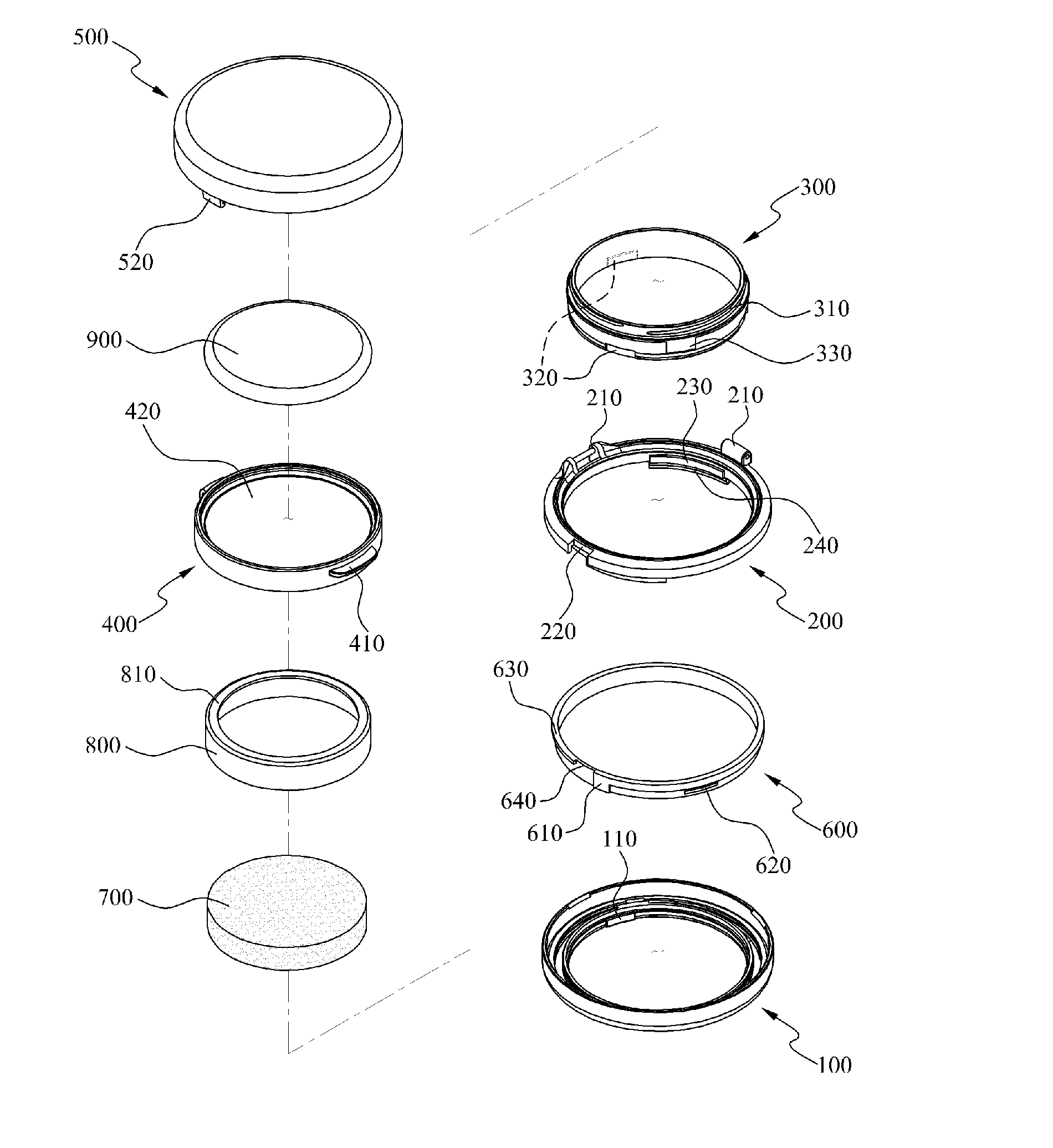
[0021] FIG. 1 is an exploded perspective view illustrating a configuration of a compact case according to an exemplary embodiment.
[0022] FIG. 2 is an assembled perspective view illustrating a configuration of a compact case according to an exemplary embodiment.
[0023] FIG. 3 is an assembled cross-sectional view illustrating a configuration of a compact case according to an exemplary embodiment.
[0024] FIGS. 4A and 4B are explanatory views illustrating an opening process of an upper case of a compact case according to an exemplary embodiment.
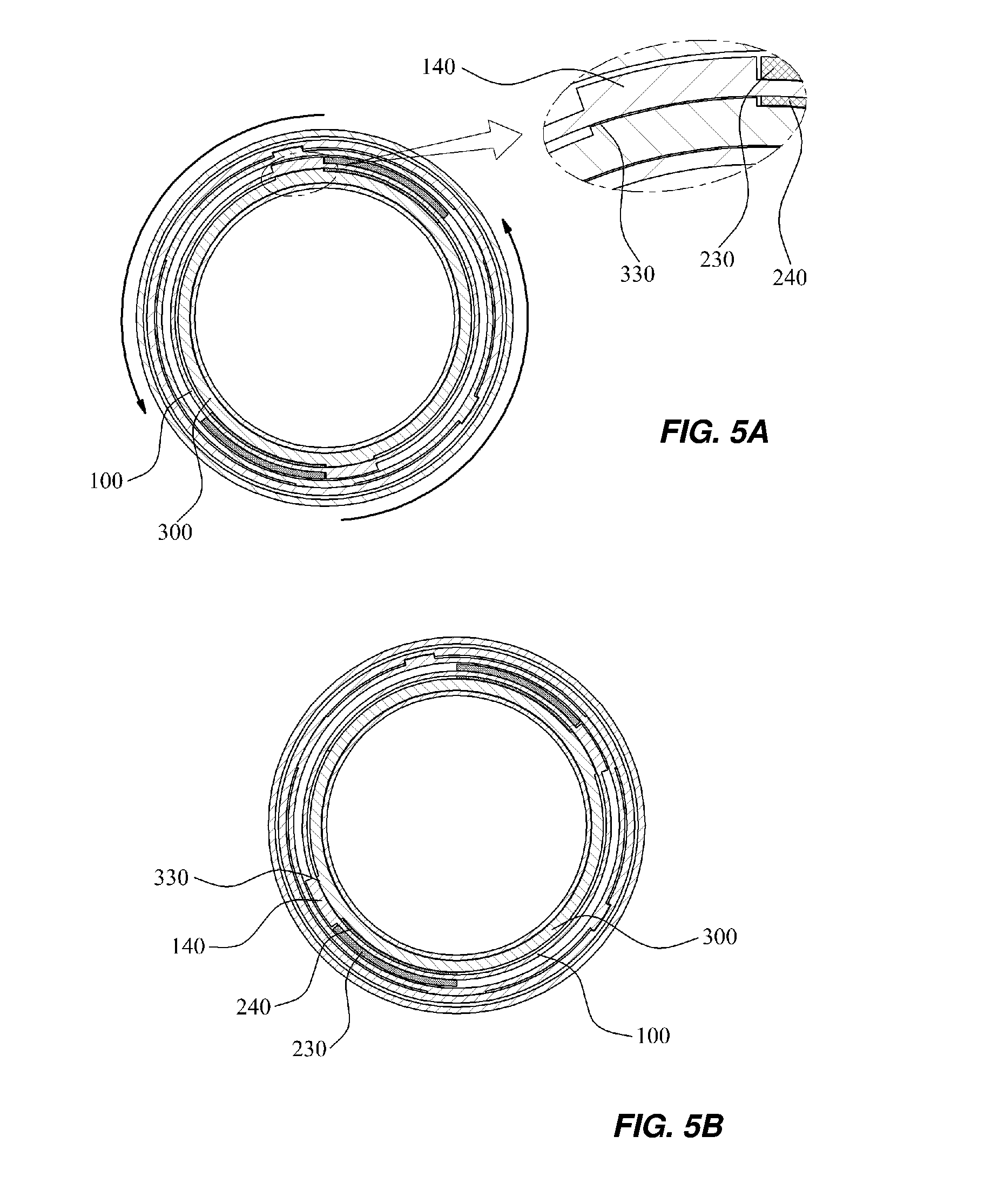
[0025] FIGS. 5A and 5B are explanatory views illustrating a rotational range of a lower case of a compact case according to an exemplary embodiment.
[0026] FIG. 6 is an exploded prospective view illustrating the coupling configuration of an upper case and a support body of a compact case according to an exemplary embodiment.
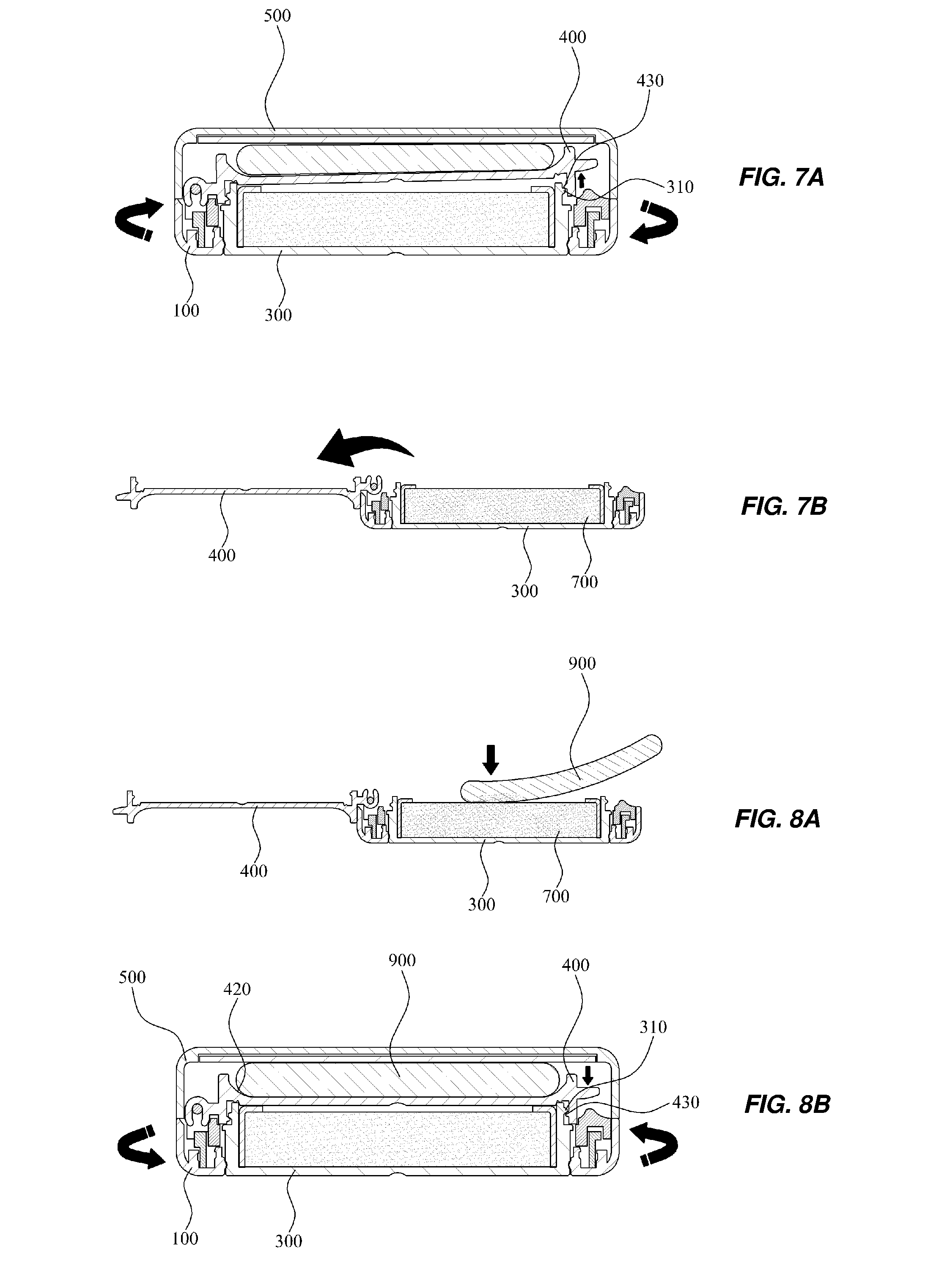
[0027] FIGS. 7A-7B and 8A-8B are explanatory views illustrating a method using a compact case according to an exemplary embodiment.
[0028] FIGS. 9A-9C are explanatory views illustrating a refilling process of a contents storage part of a compact case according to an exemplary embodiment.
DETAILED DESCRIPTION
[0029] Hereinafter, exemplary embodiments will be described in detail with reference to the accompanying drawings. The same reference numerals provided in the drawings indicate the same members.
[0030] FIG. 1 is an exploded perspective view illustrating a configuration of a compact case according to an exemplary embodiment. FIG. 2 is an assembled perspective view illustrating a configuration of a compact case according to an exemplary embodiment. FIG. 3 is an assembled cross-sectional view illustrating a configuration of a compact case according to an exemplary embodiment of the present invention.
[0031] FIGS. 4A and 4B are explanatory views illustrating an opening process of an upper case of a compact case according to an exemplary. FIGS. 5A and 5B are explanatory views illustrating a rotational range of a lower case of a compact case according to an exemplary embodiment. FIG. 6 is an exploded prospective view illustrating the coupling configuration of an upper case and a support body of a compact case according to an exemplary embodiment.
[0032] Referring to FIGS. 1 to 6, a compact case according to an exemplary embodiment may include a lower case 100, a middle case 200, a contents storage part 300, a sealing member 400, an upper case 500, and a support body 600.
[0033] The lower case 100, receiving a contents storage part 300, is provided with a coupling protrusion 110 where the contents storage part 300 is coupled such that the contents storage part 300 can rotate together according to rotation of the lower case 100 at an inner side thereof.
[0034] Furthermore, at an inner side of the lower case 100 is provided an insertion groove 120 where an insertion protrusion 610 of a support body 600 is inserted such that the support body 600 can rotate together according to rotation of the lower case 100, and at an inner side is provided a separation-preventing groove 130 where an separation-preventing protrusion 620 of the support body 600 is coupled such that the support body 600 can be prevented from being separated to an upward direction in a state that the insertion protrusion 610 is inserted to the insertion groove 120.
[0035] Meanwhile, at the lower case 100 is provided a first protrusion part 140 which meets a first rotation-limiting protrusion 230 and limits rotation of the lower case 100 in a rotational process thereof, and the first protrusion part 140 is preferably configured to be in pair which protrude to be faced each other as illustrated in FIG. 1.
[0036] The middle case 200, made of shape of a ring and rotatably coupled to an upper portion of the lower case 100, is provided with a hinge part 210 such that a sealing member 400 and an upper case 500 can be hinge-coupled at an upper end thereof and swiveled upwards and downwards, and further provided with a penetration groove 220 such that an opening/closing protrusion 520 of the upper case 500 can be penetrated.
[0037] In the described embodiments, it is characterized to be provided with a first and a second rotation-limiting protrusion 230, 240 at an inner side of the middle case 200 so as to limit the rotational range of the lower case 100 and the contents storage part 300. The first and the second rotation-limiting protrusions 230, 240, which are placed in the above and the below, respectively limits the rotational range of the lower case 100 and the contents storage part 300, and are configured to be preferably in pair which are formed with protrusion so as to correspond each other inside the middle case 200.
[0038] The contents storage part 300, coupled to an inner side of the lower case 100 and storing a contents absorption member 700 impregnated with liquid contents, is provided with a coupling groove 320 which is coupled with a coupling protrusion 110 of the lower case 100 at an outer circumferential surface thereof such that the contents storage part 300 can be coupled to an inner side of the lower case 100.
[0039] The contents absorption member 700 which is stored in the contents storage part 300 can be made of various materials such as puff, sponge, foam, and brush where liquid contents are impregnated, and preferably made of porous material which easily absorbs liquid contents.
[0040] Furthermore, at an inner side of the contents storage part 300 is provided a fixation tube 800 which encases the contents absorption member 700 so as to fix the contents absorption member 700, and at an upper portion of the fixation tube 800 is provided a fixation protrusion 810 to an inward direction such that the fixation protrusion 810 supports an upper end of the contents absorption member 700 and thereby prevents the contents absorption member 700 from being separated from the contents storage part 300.
[0041] In the described embodiments, it is characterized in that at an outer circumferential surface of the contents storage part 300 is provided a first screw thread 310 for being screw-coupled with the sealing member 400. As the contents storage part 300 interlocked with the lower case 100 rotates when rotating the lower case 100, the first screw thread 310 and a second screw thread 430 of the sealing 400 get screw-coupled, and perform a sealing process through a screw-coupling, thereby effectively preventing the contents stored in the contents storage part 300 from being leaked in a process of decompression.
[0042] Meanwhile, at an outer circumferential surface of the contents storage part 300 is provided a pair of second protrusion part 330 which meet second rotation-limiting protrusions 240 and limit the rotation of the contents storage part 300 during a rotation process by the rotation of the lower case 100, as illustrated in FIGS. 5A and 5B.
[0043] Meanwhile, as illustrated in FIGS. 9A to 9C, when all the contents, which are impregnated in the contents absorption member 700 stored in the contents storage part 300, are used up, it is possible to exchange the contents absorption member 700. In this case, it is possible easily to exchange the contents absorption member 700', by separating the contents storage part 300 from the lower case 100 in a state of swiveling the sealing member 400 upwards, and then by coupling with combined-fit the contents storage part 300 which stores a new contents storage part 700' impregnated with liquid contents.
[0044] As in the above, when the exchange of the contents absorption member 700 is complete, it is possible to use the contents impregnated in the contents absorption member 700' after a sealing tape (S) which is attached on an upper end of the contents storage part 300 to prevent the evaporation of the contents impregnated in the contents absorption member 700'.
[0045] The sealing member 400 is hinge-coupled to the middle case 200 to open/close the open upper end of the contents storage part 300, wherein a handle part 410 is provided at a front surface thereof for easy controlling when swiveling upwards and downwards according to the hinge combination, and a reception groove 420 is provided at an upper portion thereof such that a contents application member 900 such as puff can be received therein.
[0046] In the described embodiments, it is characterized in that at an inner circumferential surface of the sealing member 400 is provided a second screw thread 430 which is screw-coupled with the first screw thread 310 of the contents storage part 300. As illustrated in the above, since a sealing process is performed by closing the open upper end of the content storage part 300 by means of the screw combination, it is possible to effectively prevent the contents stored in the contents storage part 300 from being leaked in a process of decompression.
[0047] The upper case 500, which encases the contents application member 900 and is hinge-coupled to the middle case 200 for being able to be swiveled upwards and downwards, allows the contents application member 900 to be used when swiveled upwards to be opened, and protects the contents application member 900 from external impact and also prevents foreign substance from entering a reception groove 420 when swiveled downwards to be closed. In addition, it is preferable that a mirror 510 is installed at an inner side of the upper case 500 for a user to check her make-up area when applying contents on her face.
[0048] In the described embodiments, it is characterized in that at a front surface of the upper case 500 is provided an opening/closing protrusion 520 which controls opening/closing of the upper case 500. The opening/closing protrusion 520, as illustrated in FIGS. 4A and 4B, is supported by a protrusion 630 of a support 600 in a normal state and prevents the upper case 500 from being opened. Then, when broken away from the protrusion 630 by the rotation of the upper case 500 and placed in a guide groove 640, the opening/closing protrusion 520 allows the upper case 500 to open.
[0049] The support 600 is made of a ring shape which is coupled to an inner side of the lower case 100 and rotates together by rotation of the lower case 100. At an outer circumferential surface of the support body 600, as illustrated in FIG. 6, is provided an insertion protrusion 610 which is inserted to an insertion groove 120 of the lower case 100 for being able to rotate together according to rotation of the lower case 100.
[0050] Furthermore, at an outer side of the support body 600 is provided a separation-preventing protrusion 620 which is inserted to a separation-preventing groove 130 of the lower case 100 such that the support body 600 is prevented from moving upwards and being separated from the lower case 100.
[0051] Meanwhile, at an outer circumferential surface of the support body 600 is provided a protrusion 630 which supports the opening/closing protrusion 520 of the upper case 500 and prevents the upward swiveling of the upper case 500, wherein at a dead end of the protrusion 630 is provided a guide groove 640 which guides an upward swiveling of the upper case 500.
[0052] Hereinafter, referring to FIGS. 7A, 7B, 8A, and 8B, a method of using a compact case according to an exemplary embodiment will be described.
[0053] First, as illustrated in FIGS. 7A and 7B, when the lower case 100 is rotated to one side direction in a state of grabbing the upper case 500, the contents storage part 300 which is interlocked with the lower case 100 rotates together. Due to this, the first screw thread 310 of the contents storage part 300 and the second screw thread 430 of the sealing member 400 are released from the screw-combination and thereby the sealing member 400 ascends in a narrow range.
[0054] At this, the lower case 100, as illustrated in FIGS. 5A and 5B, rotates up to the point where the first protrusion part 140 meets the first rotation-limiting protrusion 230.
[0055] As in the above, when the first screw thread 310 of the contents storage part 300 and the second screw thread 430 of the sealing member 400 are released from the screw-combination, a user swivels in an upward direction, and opens the upper case 500 and the sealing member 400 in order, and as illustrated in FIGS. 8A and 8B, can smear the contents impregnated in the contents absorption member 700 by means of the contents application member 900 and apply onto her face.
[0056] Next, after completing application of contents by means of the contents application member 900, a user swivels the sealing member 400 to a downward direction and receives the contents application member 900 in the reception groove 420, and then swivels the upper case 500 to an upward direction.
[0057] As described in the above, if the lower case 100 is rotated to the other direction after grabbing the upper case 500 in a state of swiveling the upper case to a downward direction, as the contents storage part 300 interlocked with the lower case 100 rotates together, the first screw thread 310 of the contents storage part 300 and the second screw thread 430 of the sealing member 400 get screw-coupled and make the sealing member 400 descend in a narrow range. Due to this, the sealing process is performed in accordance with the closing of the open upper end of the contents storage part 300 by the sealing member 400.
[0058] In the contemplated embodiments, as described above, as the open upper end of the contents storage part 300 gets closed by a sealing structure by means of a screw combination of the contents storage part 300 and the sealing member 400, it is possible to effectively prevent the leakage of contents.
[0059] As described above, embodiments have been disclosed in the drawings and the specification. Although specific terms have been used herein, these are only intended to describe the embodiments and are not intended to limit the meanings of the terms or to restrict the scope of the accompanying claims. Therefore, those skilled in the art will appreciate that various modifications and other equivalent embodiments are possible from the above embodiments. Therefore, the scope of the claims below should be construed according to the technical spirit of the description above.
* * * * *
D00000
D00001
D00002
D00003
D00004
D00005
D00006
D00007
XML
uspto.report is an independent third-party trademark research tool that is not affiliated, endorsed, or sponsored by the United States Patent and Trademark Office (USPTO) or any other governmental organization. The information provided by uspto.report is based on publicly available data at the time of writing and is intended for informational purposes only.
While we strive to provide accurate and up-to-date information, we do not guarantee the accuracy, completeness, reliability, or suitability of the information displayed on this site. The use of this site is at your own risk. Any reliance you place on such information is therefore strictly at your own risk.
All official trademark data, including owner information, should be verified by visiting the official USPTO website at www.uspto.gov. This site is not intended to replace professional legal advice and should not be used as a substitute for consulting with a legal professional who is knowledgeable about trademark law.