Shoe Cover
TSAI; CHIH JEN
U.S. patent application number 16/021589 was filed with the patent office on 2019-01-03 for shoe cover. The applicant listed for this patent is CHIH JEN TSAI. Invention is credited to CHIH JEN TSAI.
| Application Number | 20190000178 16/021589 |
| Document ID | / |
| Family ID | 63143821 |
| Filed Date | 2019-01-03 |


View All Diagrams
| United States Patent Application | 20190000178 |
| Kind Code | A1 |
| TSAI; CHIH JEN | January 3, 2019 |
SHOE COVER
Abstract
A shoe cover comprising: a body having a shoe-covering portion and an edge portion, the shoe-covering portion being used for covering a front part of a shoe, the edge portion extending along a lower edge of the shoe-covering portion and disposed below the shoe; and a cap extending along an upper edge of the shoe-covering portion of the body and disposed above the shoe, an upper surface of the cap having at least one water guiding slot used for directing water droplets to drip downwards.
| Inventors: | TSAI; CHIH JEN; (Keelung, TW) | ||||||||||
| Applicant: |
|
||||||||||
|---|---|---|---|---|---|---|---|---|---|---|---|
| Family ID: | 63143821 | ||||||||||
| Appl. No.: | 16/021589 | ||||||||||
| Filed: | June 28, 2018 |
| Current U.S. Class: | 1/1 |
| Current CPC Class: | A43B 3/20 20130101; A43B 7/12 20130101; A43B 3/18 20130101; A43B 3/166 20130101 |
| International Class: | A43B 3/16 20060101 A43B003/16; A43B 7/12 20060101 A43B007/12; A43B 3/18 20060101 A43B003/18; A43B 3/20 20060101 A43B003/20 |
Foreign Application Data
| Date | Code | Application Number |
|---|---|---|
| Jun 30, 2017 | TW | 106121963 |
| Jun 20, 2018 | TW | 107121058 |
Claims
1. A shoe cover, comprising: a body having a shoe-covering portion and an edge portion, the shoe-covering portion being used for covering a front part of a shoe, the edge portion extending along a lower edge of the shoe-covering portion and disposed below the shoe; and a cap extending along an upper edge of the shoe-covering portion of the body and disposed above the shoe, an upper surface of the cap having at least one water guiding slot used for directing water droplets to drip downwards.
2. The shoe cover of claim 1, wherein the cap has a plurality of holes which allow a shoelace of the shoe to pass through and be fastened, so that the shoe-covering portion can be fastened onto and cover the front part of the shoe.
3. A shoe cover for covering a front part of a shoe, comprising: a body having a shoe-covering portion, an edge portion and a fastening device, the edge portion extending along a lower edge of the shoe-covering portion, the fastening device extending along both sides of the shoe-covering portion, wherein the shoe-covering portion, the edge portion and the fastening device are formed as one piece.
4. A shoe cover for covering a front part of a shoe, comprising: a body having a shoe-covering portion and an edge portion, the edge portion extending along a lower edge of the shoe-covering portion, a pivot portion being disposed on an upper edge of the shoe-covering portion and having a tunnel which allows a shoelace of the shoe to pass through and be fastened, so that the shoe-covering portion is disposed onto and covers the front part of the shoe; and a cap having a pivot hinge unit at the front part, the pivot hinge unit being hinged upon the pivot portion of the shoe-covering portion, so that the cap is able to pivotally move relative to the shoe-covering portion.
5. The shoe cover of claim 4, wherein the cap has a plurality of holes which allow the shoelace of the shoe to pass through and be fastened.
6. A shoe cover for covering a front part of a shoe, comprising: a body having a shoe-covering portion and an ear-like portion, the shoe-covering portion being formed of a waterproof fabric supported by a plurality of supports, the ear-like portion extending along both sides of the shoe-covering portion; and an elastic strap being attached to the ear-like portion and used for fastening the shoe-covering portion onto the front part of the shoe.
7. The shoe cover of claim 6, wherein the shoe cover further comprises a cap extending along an upper edge of the shoe-covering portion of the body and disposed above the shoe.
8. A shoe cover, comprising: a cap having a hook portion and a shoe-covering portion having a fastening portion, the hook portion being hooked and buckled onto the fastening portion to allow the cap and the shoe-covering portion to form the shoe cover, so that the shoe cover is disposed onto and covers a front part of a shoe having a shoelace, wherein a 3-dimensional structure comprising the cap and the shoe-covering portion is formed by folding a first paper card and a second paper card, and wherein the first paper card and the second paper card are detached from a flat paper card.
9. The shoe cover of claim 8, wherein: an upper part of the cap has a plurality of holes; both sides of the cap have a respective wing-like portion extending outward; a folding line is provided on a lower part of the cap; a shoelace of the shoe is able to pass through the holes on the cap so that the cap is fastened onto and covers the shoe; and the folding line of the cap is able to form the hook portion when folded.
10. The shoe cover of claim 8, wherein an upper part of the shoe-covering portion has a plurality of holes, and a shoelace of the shoe is able to pass through the holes of the shoe-covering portion.
11. The shoe cover of claim 8, wherein the shoe-covering portion has a plurality of ear-like portions and adhering portions, and the adhering portions are able to stick to each other to form a 3-dimensional structure when the ear-like portions are folded inward, so that the shoe-covering portion can fit a shape of the shoe.
12. A shoe cover, comprising: a shoe-covering portion having a pivot portion and a plurality of first slots, the first slots being provided at both sides of the pivot portion; a connecting portion having a plurality of second slots and at least one tunnel, the second slots being counterparts to the first slots of the shoe-covering portion; a combining element being buckled onto the first slots and the second slots after the first slots and the second slots have been overlapped with each other, so that the connecting portion and the shoe-covering portion can slide relative to each other; and a cap having a hook portion, the hook portion being hooked and buckled onto the pivot portion of the shoe-covering portion to allow the cap, the connecting portion and the shoe-covering portion to form the shoe cover, so that the shoe cover is disposed onto and covers a front part of a shoe having a shoelace.
13. The shoe cover of claim 12, wherein the tunnel of the connecting portion allows the shoelace of the shoe to pass through and be fastened, and a plurality of holes are further provided on the cap to allow the shoelace of the shoe to pass through and be fastened.
14. The shoe cover of claim 12, wherein the hook portion of the cap is formed as one piece or two pieces.
Description
CROSS REFERENCE TO RELATED APPLICATION
[0001] This application also claims priority to Taiwan Patent Application No. 107121058 filed in the Taiwan Patent Office on Jun. 20, 2018 and 106121963 on Jun. 30, 2017, the entire content of which is incorporated herein by reference.
BACKGROUND
Technical Field
[0002] The present disclosure relates to a shoe cover, and more particularly to a shoe cover that is made of a heat moldable material, waterproof, and able to cover a shoe to keep splash off the shoe.
Description of Related Art
[0003] In Taiwan, where the weather is often rainy and humid, rain boots are worn outdoors on rainy days. Meanwhile, boot wearers tend to carry an extra pair of shoes and change their rain boots to the extra pair of footwear upon their arrival at destination. However, not only are conventional rain boots heavy, they somehow cause inconvenience because a user will be required to change their footwear at the destination. The poor foldability of conventional rain boots also adds to the problem, causing a trouble to the user when it comes to stashing away the changed pair of footwear. Although various foldable rain boots have been developed and manufactured, their considerable volume when folded still fails to meet the user's needs.
[0004] As commuting methods have become more convenient than ever, needs for a sturdy pair of rain boots have been diminishing; instead, what is increasingly sought after are thin and lightweight waterproof shoe covers. A user putting on waterproof shoe covers will only be required to remove them upon arrival at destination and thus spared from the effort of changing footwear. Thin and lightweight shoe covers have more advantages over rain boots in terms of their high foldability that allows them to be easily stashed away. In addition, the manufacturing cost of waterproof shoe covers is lower than that of hardened rain boots. Upon arriving at destination, a user may even discard their shoe covers right away.
[0005] In view of the above, it is worth developing a type of easy-to-wear waterproof shoe covers that users will be more eager to carry around.
SUMMARY
[0006] An object of the present disclosure is to provide a shoe cover that covers the outside of a shoe to protect the shoe from rainwater. The shoe cover according to the present disclosure can be cleaned easily and directly with water. With various lightweight and elegant designs proposed, such shoe cover is also easy to use and carry around.
[0007] A shoe cover achieving the above aspects comprises: a body having a shoe-covering portion and an edge portion, the shoe-covering portion being used for covering the front part of a shoe, the edge portion extending along the lower edge of the shoe-covering portion and disposed below the shoe; and a cap extending along the upper edge of the shoe-covering portion of the body and disposed above the shoe, the upper surface of the cap having at least one water guiding slot used for directing water droplets to drip downwards.
[0008] Preferably, the cap has a plurality of holes which allow the shoelace of the shoe to pass through and be fastened, so that the shoe-covering portion can be fastened onto and cover the front part of the shoe.
[0009] Another shoe cover achieving the above aspects comprises: a body having a shoe-covering portion, an edge portion and a fastening device, the edge portion extending along the lower edge of the shoe-covering portion, the fastening device extending along both sides of the shoe-covering portion, wherein the shoe-covering portion, the edge portion and the fastening device are formed as one piece.
[0010] A further shoe cover achieving the above aspects comprises: a body having a shoe-covering portion and an edge portion, the edge portion extending along the lower edge of the shoe-covering portion, a pivot portion being disposed on the upper edge of the shoe-covering portion and having a tunnel which allows a shoelace to pass through and be fastened onto the shoe, so that the shoe-covering portion is disposed onto and covers the front part of the shoe; and a cap having a pivot hinge unit at the front part, the pivot hinge unit being hinged upon the pivot portion of the shoe-covering portion, so that the cap is able to pivotally move relative to the shoe-covering portion.
[0011] Preferably, the cap has a plurality of holes which allow the shoelace of the shoe to pass through and be fastened.
[0012] A further shoe cover achieving the above aspects comprises: a body having a shoe-covering portion and an ear-like portion, the shoe-covering portion being formed of a waterproof fabric supported by a plurality of supports, the ear-like portion extending along both sides of the shoe-covering portion; and an elastic strap being attached to the ear-like portion and used for fastening the shoe-covering portion onto the front part of the shoe.
[0013] Preferably, the shoe cover further comprises a cap extending along the upper edge of the shoe-covering portion of the body and disposed above the shoe.
[0014] A further shoe cover achieving the above aspects comprises: a cap having a hook portion and a shoe-covering portion having a fastening portion, the hook portion being hooked and buckled onto the fastening portion to allow the cap and the shoe-covering portion to form the shoe cover, so that the shoe cover is disposed onto and covers the front part of a shoe having a shoelace, wherein a 3-dimensional structure comprising the cap and the shoe-covering portion is formed by folding a first paper card and a second paper card, and wherein the first paper card and the second paper card are detached from a flat paper card.
[0015] Preferably, the upper part of the cap has a plurality of holes, and both sides of the cap have a respective wing-like portion extending outward, while a folding line is disposed on the lower part of the cap; a shoelace of the shoe is able to pass through the holes on the cap so that the cap is fastened onto and covers the shoe; and the folding line of the cap is able to form the hook portion when folded.
[0016] Preferably, the upper part of the shoe-covering portion has a plurality of holes, and a shoelace of the shoe is able to pass through the holes of the shoe-covering portion and be fastened.
[0017] Preferably, the shoe-covering portion has a plurality of ear-like portions and adhering portions, and the adhering portions are able to stick to each other to form a 3-dimensional structure when the ear-like portions are folded inward, so that the shoe-covering portion can fit the shape of the shoe.
[0018] A further shoe cover achieving the above aspects comprises: a shoe-covering portion having a pivot portion and a plurality of first slots, the first slots being provided at both sides of the pivot portion; a connecting portion having a plurality of second slots and tunnels, the second slots being counterparts to the first slots of the shoe-covering portion; a combining element being buckled onto the first slots and the second slots after they have been overlapped with each other, so that the connecting portion and the shoe-covering portion can slide relative to each other; and a cap having a hook portion, the hook portion being hooked and buckled onto the pivot portion of the shoe-covering portion to allow the cap, the connecting portion and the shoe-covering portion to form the shoe cover, so that the shoe cover is disposed onto and covers the front part of a shoe having a shoelace.
[0019] Preferably, the tunnel of the connecting portion allows a shoelace of the shoe to pass through and be fastened, and a plurality of holes are further provided on the cap to allow the shoelace of the shoe to pass through and be fastened.
[0020] Preferably, the hook portion of the cap is formed as one piece or two pieces.
BRIEF DESCRIPTION OF THE DRAWINGS
First Embodiment
[0021] FIG. 1A is a perspective view showing a shoe cover according to the present disclosure;
[0022] FIG. 1B is another perspective view of the shoe cover;
[0023] FIG. 1C is a perspective view showing the shoe cover covering a shoe; and
[0024] FIG. 1D is a bottom view showing the shoe cover covering a shoe.
Second Embodiment
[0025] FIG. 2A is a perspective view showing a shoe cover according to the present disclosure;
[0026] FIG. 2B is another perspective view of the shoe cover; and
[0027] FIG. 2C is a perspective view showing the shoe cover covering a shoe.
Third Embodiment
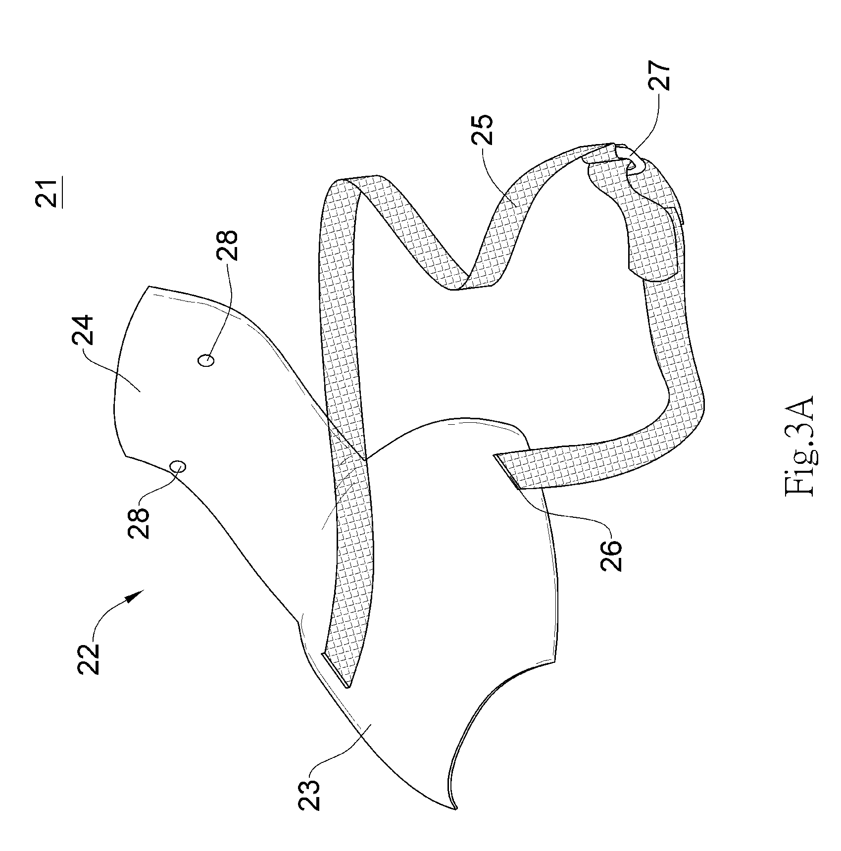
[0028] FIG. 3A is a perspective view showing a shoe cover according to the present disclosure;
[0029] FIG. 3B is another perspective view of the shoe cover;
[0030] FIG. 3C is a perspective view showing the shoe cover covering a shoe; and
[0031] FIG. 3D is a bottom view showing the shoe cover covering a shoe.
Fourth Embodiment
[0032] FIG. 4A is a perspective view showing a shoe cover according to the present disclosure;
[0033] FIG. 4B is another perspective view of the shoe cover; and
[0034] FIG. 4C is a perspective view showing the shoe cover covering a shoe.
Fifth Embodiment
[0035] FIG. 5A is a perspective view showing a shoe cover according to the present disclosure; and
[0036] FIG. 5B is a perspective view showing the shoe cover covering a shoe.
Sixth Embodiment
[0037] FIG. 6A is an exploded view showing a shoe cover according to the present disclosure; and
[0038] FIG. 6B is a perspective view showing the shoe cover in an assembled state.
Seventh Embodiment
[0039] FIG. 7A is a top view showing a shoe cover according to the present disclosure covering a shoe; and
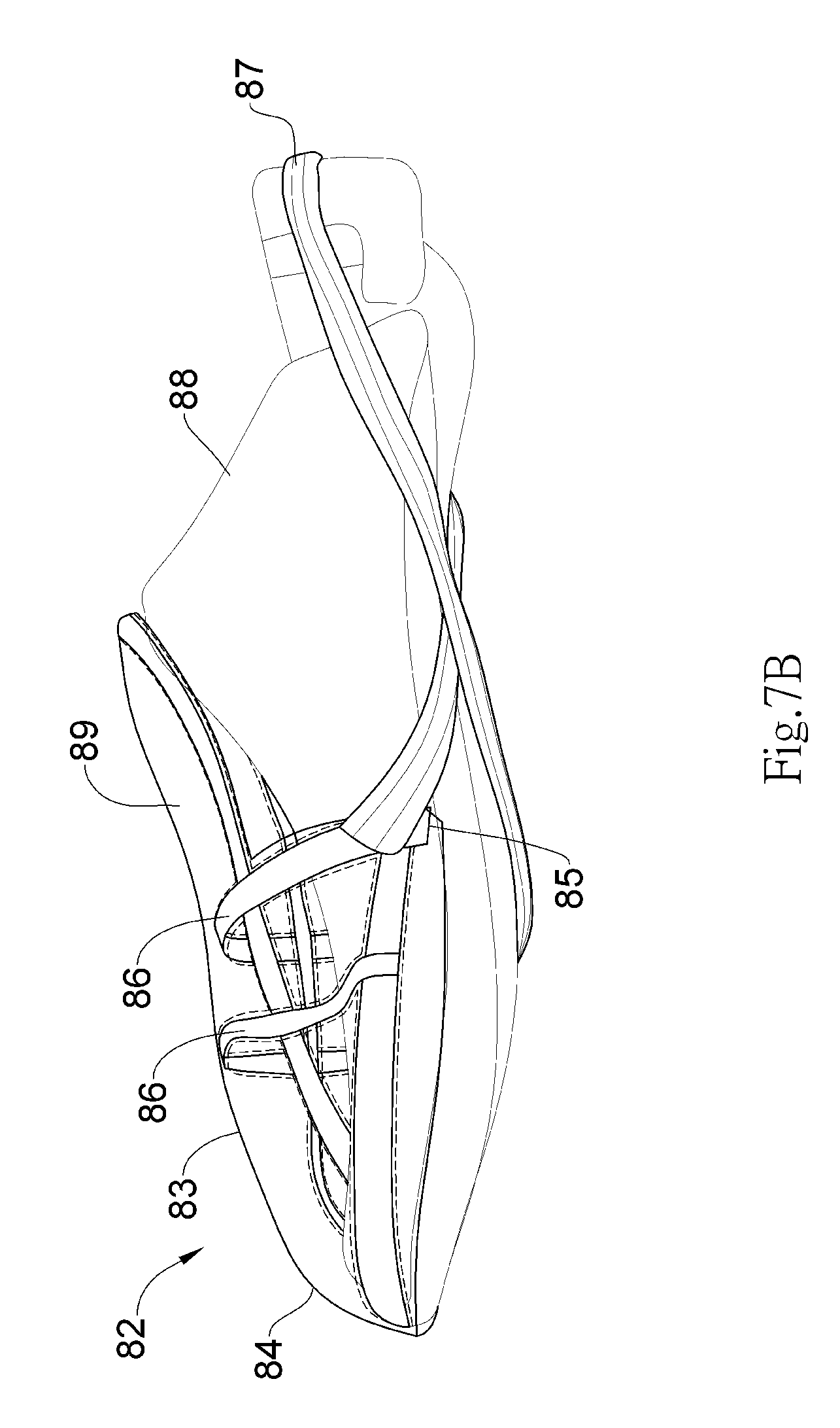
[0040] FIG. 7B is a side view showing the shoe cover covering a shoe.
Eighth Embodiment
[0041] FIG. 8A is a top view showing a shoe cover according to the present disclosure formed from a paper card.
[0042] FIG. 8B is a perspective view showing the shoe cover covering a shoe.
Ninth Embodiment
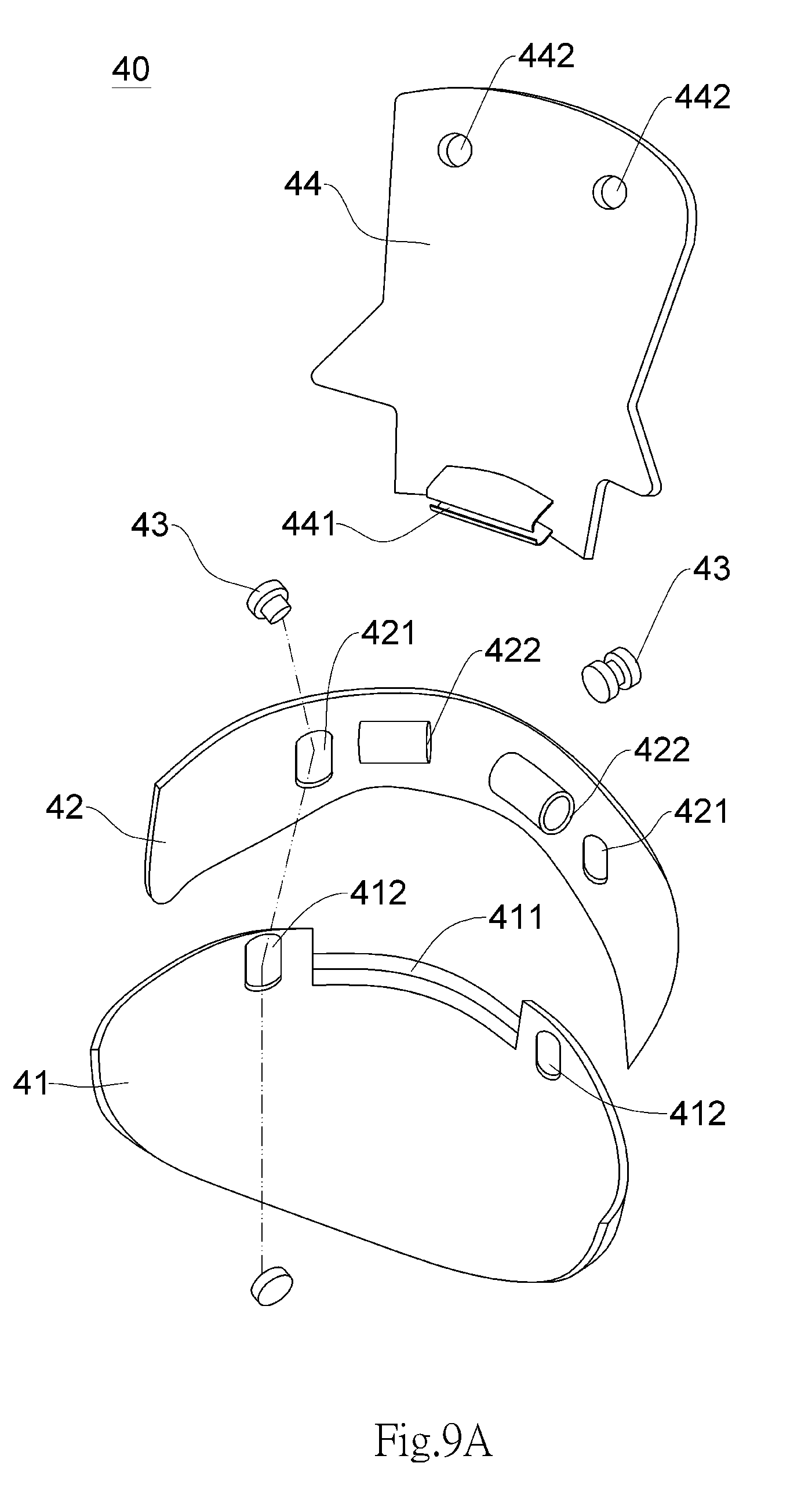
[0043] FIG. 9A is an exploded view showing a shoe cover according to the present disclosure.
[0044] FIG. 9B is a top view showing the shoe cover in an assembled state.
DETAILED DESCRIPTION
[0045] Although the present disclosure will be fully described with reference to the drawings showing preferred embodiments of the invention, it shall be understood, before reading such description, that a person ordinarily skilled in the art could achieve the same effects of the present disclosure by making modifications to the invention described herein. Therefore, it shall be understood that the following description is a generic disclosure to a person ordinarily skilled in the art, and does not intend to limit the scope of the present disclosure.
[0046] Please refer to FIGS. 1A, 1B, 1C and 1D showing a shoe cover 1 according to a first embodiment of the present disclosure. A perspective view of the shoe cover, another perspective view of the shoe cover, a perspective view of the shoe cover covering a shoe, and a bottom view of the shoe cover covering a shoe are shown in the above drawings, respectively. In this preferred embodiment, the shoe cover 1 comprises: a body 2 having a shoe-covering portion 3, an edge portion 4 and an ear-like portion 5, the edge portion 4 extending along the lower edge of the shoe-covering portion 3 and having a flat shape, the ear-like portion 5 extending along both sides of the shoe-covering portion 3; and an elastic strap 6 attached to the ear-like portion 5. The ear-like portion 5 has a square shape and is perpendicular to the edge portion 4, and each ear-like portion 5 has a hole 7, both of which allow both ends of the elastic strap 6 to pass through to be tied together. The elastic strap 6 is used for fastening the shoe-covering portion 3 onto the front part of a shoe 8.
[0047] Please refer particularly to FIGS. 1C and 1D, in which the shoe cover 1 according to the present disclosure covers part of the shoe 8, the shoe-covering portion 3 having a curved shape designed for covering the front part of the shoe 8, the edge portion 4 extending under the shoe 8. The elastic strap 6 made of an elastic material may be first crossed (as shown in FIG. 1D) and then fitted to the rear of the shoe 8, so as to fasten the shoe cover 1 onto the shoe 8, thereby preventing the shoe cover 1 from falling off. The body 2 may be made of a waterproof material such as paper, rubber or umbrella fabric. Thus, with the shoe cover 1 covering the front part of the shoe 8, the body 2 is able to effectively protect the shoe 8 from rainwater, thereby preventing the wearer of the shoe 8 with the shoe cover 1 from feeling wet and uncomfortable.
[0048] Please refer to FIGS. 2A, 2B and 2C showing a shoe cover 11 according to a second embodiment of the present disclosure. A perspective view of the shoe cover, another perspective view of the shoe cover and a perspective view of the shoe cover covering a shoe are shown in the above drawings, respectively. In this preferred embodiment, the shoe cover 11 comprises: a body 12 having a shoe-covering portion 13 and an edge portion 14, the shoe-covering portion 13 being used for covering the front part of a shoe 17, the edge portion 14 extending along the lower edge of the shoe-covering portion 13, right below the shoe 17, wherein the edge portion 14 has a flat shape; and a cap 15 extending along the upper edge of the shoe-covering portion 13 of the body 12, right above the shoe 17, wherein a plurality of holes 16 are disposed on the cap 15, the holes 16 being able to be tied with the shoelace 18 of the shoe 17, so that the shoe cover 11 can be fastened onto the shoe 17. It is worth noting that the upper surface of the cap 15 has a plurality of water guiding slots 19 which are, with a certain length and width, used for directing water droplets to drip downwards. When the shoe cover 11 is disposed on the shoe 17, the body 12 is able to keep rainwater from splashing onto the shoe 17, so as to prevent the wearer of the shoe 17 with the shoe cover 1 lfrom feeling to wet and uncomfortable. The water guiding slots 19 are able to direct water droplets to drip downwards.
[0049] Please refer to FIGS. 3A, 3B, 3C and 3D showing a shoe cover 21 according to a third embodiment of the present disclosure. A perspective view of the shoe cover, another perspective view of the shoe cover, a perspective view of the shoe cover covering a shoe, and a bottom view of the shoe cover covering a shoe are shown in the above drawings, respectively. In this preferred embodiment, the shoe cover 21 comprises: a body 22 having a shoe-covering portion 23 and a cap 24, the cap 24 extending along the upper edge of the shoe-covering portion 23, a plurality of holes 28 being disposed at the rear of the cap 24; and a fastening device 25 being attached to the lower edge of the shoe-covering portion 23 of the body 22, wherein a plurality of holes 26 are disposed on the lower edge of the shoe-covering portion 23 of the body 22, and allow the fastening device 25 to pass through and be attached. It is worth noting that the fastening device 25 is a Velcro strap with an adjustable length. In this preferred embodiment, the Velcro strap passes through a buckle 27 and has an adjustable length. The holes 28 allow the shoelace 30 of a shoe 29 to pass through and be fastened, thereby fastening the shoe cover 21 onto the shoe 29. The fastening device 25 is used for fastening the shoe-covering portion 23 onto the front part of the shoe 29, so that the cap 24 is disposed above the shoe 29.
[0050] Please refer particularly to FIGS. 3C and 3D, in which the shoe cover 21 according to the present disclosure covers part of a shoe 29. The shoe-covering portion 23 has a curved shape designed for covering the front part of the shoe 29; the cap 24 covers the upper part of the shoe 29; and the fastening device 25 may be first crossed (as shown in FIG. 3D) and then buckled at the rear of the shoe 29, so as to fasten and cover the shoe cover 21 onto the shoe 29, thereby preventing the shoe cover 21 from falling off. The body 22 may be made of a waterproof material such as paper, rubber or umbrella fabric. Thus, with the shoe cover 21 covering the shoe 29, the body 22 is able to effectively protect the shoe 29 from rainwater, thereby preventing the wearer of the shoe 29 with the shoe cover 21 from feeling wet and uncomfortable.
[0051] Please refer to FIGS. 4A, 4B and 4C showing a shoe cover 31 according to a fourth embodiment of the present disclosure. A perspective view of the shoe cover, another perspective view of the shoe cover and a perspective view of the shoe cover covering a shoe are shown in the above drawings, respectively. In this preferred embodiment, the shoe cover 31 comprises: a body 32 having a shoe-covering portion 33, an edge portion 34 and a fastening device 35, the edge portion 34 extending along the lower edge of the shoe-covering portion 33, the fastening device 35 extending along both sides of the shoe-covering portion 33, wherein the shoe-covering portion 33, the edge portion 34 and the fastening device 35 are formed as one piece made of a material which is similar to a heat moldable material as used in disposable ponchos, or made of a rubber material. The material would make the shoe cover 31 extremely thin and light, and thus easy to carry around.
[0052] Please refer particularly to FIG. 4C, in which the shoe cover 31 according to the present disclosure covers the front part of a shoe 36. The shoe-covering portion 33 has a curved shape designed for covering the front part of the shoe 36, and the fastening device 35 is fitted to the rear of the shoe 36, so as to fasten and cover the shoe cover 31 of onto the shoe 36, thereby preventing the shoe cover 31 from falling off. The body 32 is made of a waterproof material similar to that used in disposable ponchos, or of a rubber material. Thus, with the shoe cover 31 covering the front part of the shoe 36, the body 32 is able to effectively protect the shoe 36 from rainwater, thereby preventing the wearer of the shoe 36 with the shoe cover 31 from feeling wet and uncomfortable.
[0053] Please refer to FIGS. 5A and 5B showing a shoe cover 61 according to a fifth embodiment of the present disclosure. A perspective view of the shoe cover and a perspective view of the shoe cover covering a shoe are shown in the above drawings, respectively. In this preferred embodiment, the shoe cover 61 comprises: a body 62 having a shoe-covering portion 63 and an edge portion 64, the edge portion 64 extending along the lower edge of the shoe-covering portion 63; and a fastening device 65 being attached to the edge portion 64 of the body 62, wherein holes 66 are disposed on two opposite end portions of the edge portion 64 of the body 62, and allow the fastening device 65 to pass through and be attached. It is worth noting that at each of the two end portions of the fastening device 65 is a hard, L-shaped buckle 67, and that at the middle of the fastening device 65 is an elastic strap 68 being flexible and stretchable. In this preferred embodiment, the L-shaped buckle 67 at an end portion of the fastening device 65 is first buckled through the hole 66 on the edge portion 64 before covering the shoe 69 with the shoe cover 61. When the shoe cover 61 is disposed onto a shoe 69, the L-shaped buckle 67 at the other end portion of the fastening device 65 is then buckled through the other hole 66 on the edge portion 64 to successfully cover the shoe 69.
[0054] Please refer to FIGS. 6A and 6B showing a shoe cover 71 according to a sixth embodiment of the present disclosure. An exploded view of the shoe cover and an assembled view of the shoe cover are shown in the above drawings, respectively. In this preferred embodiment, the shoe cover 71 comprises: a body 72 having a shoe-covering portion 73 and an edge portion 74, the edge portion 74 extending along the lower edge of the shoe-covering portion 73, a pivot portion 75 being disposed on the upper edge of the shoe-covering portion 73; and a cap 76, a pivot hinge unit 77 being disposed at the front part of the cap 76 and hinged upon the pivot portion 75 of the shoe-covering portion 73, so that the cap 76 may pivotally move relative to the shoe-covering portion 73. It is worth noting that the pivot portion 75 of the shoe-covering portion 73 has a tunnel which allows the shoelace of a shoe to pass through, so that the shoe-covering portion 73 is disposed onto and covers the front and upper part of the shoe; meanwhile, the cap 76 has a plurality of holes 78 which allow the shoelace of the shoe to pass through and fasten the cap 76. In addition, a plurality of anti-slip portions 79 are disposed on the inward-facing side of the edge portion 74 and contact the outer surface of the shoe, thereby fastening the shoe-covering portion 73 onto the shoe and preventing any relative sliding when the shoe-covering portion 73 covers the front and upper part of the shoe. The anti-slip portions 79 have geometric shapes, which, in this embodiment, are a beaded shape. However, the geometric shapes of the anti-slip portions 79 are not limited to the shape mentioned in the embodiment; the anti-slip portions 79 may also have a bar shape or an irregular shape.
[0055] Please refer to FIGS. 7A and 7B showing a shoe cover 81 according to a seventh embodiment of the present disclosure. A top view and a side view of the shoe cover covering a shoe are shown in the above drawings, respectively. In this preferred embodiment, the shoe cover 81 comprises: a body 82 having a shoe-covering portion 84 and an ear-like portion 85, the shoe-covering portion 84 being formed of a waterproof fabric 83 supported by a plurality of supports 86, the waterproof fabric 83 having a tunnel with a network of intersecting and connecting tunnels, the plurality of supports 86 being disposed within the tunnels and used for stretching the waterproof fabric 83, the ear-like portion 85 extending along both sides of the shoe-covering portion 84; and an elastic strap 87 being attached to the ear-like portion 85 and used for fastening the shoe-covering portion 84 onto the front part of a shoe 88. It is worth noting that the supports 86 are made of a flexible material and thus able to flexibly stretch the waterproof fabric 83. The shoe cover 81 according to the present disclosure further comprises a cap 89 extending along the upper edge of the shoe-covering portion 84 of the body 82, right above the shoe 88.
[0056] Please refer to FIGS. 8A and 8B showing a shoe cover 91 according to an eighth embodiment of the present disclosure. A top view of the shoe cover formed from a paper card, and a perspective view of the shoe cover covering a shoe are shown in the above drawings, respectively. In this preferred embodiment, the shoe cover 91 comprises: a cap 92 having a hook portion 921, as well as a shoe-covering portion 93 having a fastening portion 931. The upper part of cap 92 has a plurality of holes 922; both sides of cap 92 have a respective wing-like portion 923 extending outward; and a folding line 924 is provided on the lower part of cap 92. Cap 92 and shoe-covering portion 93 are formed by folding a first paper card 100 and a second paper card 200 into a 3-dimensional structure, respectively, and then first paper card 100 and second paper card 200 are detached from flat paper card 300; it is worth noting that first paper card 100 and second paper card 200 are made of waterproof materials. Paper card 300 has a plurality of score lines (such as the dashed lines shown in FIG. 8A), along which the user can detach first paper card 100 and second paper card 200 from paper card 300. Folding line 924 of cap 92 can be folded to form hook portion 921. Shoe-covering portion 93 has a plurality of ear-like portions 932 and adhering portions 933; a 3-dimensional structure is formed when ear-like portions 932 are folded inward and adhering portions 933 stick to each other, allowing shoe-covering portion 93 to fit the shape of a shoe 98. When hook portion 921 is hooked and buckled onto fastening portion 931, cap 92 and shoe-covering portion 93 can form shoe cover 91, which is disposed onto and covers the front part of shoe 98 having a shoelace 99. Shoelace 99 can pass through holes 922 of cap 92 to allow cap 92 to be fastened onto and cover shoe 98. The upper part of shoe-covering 93 has a plurality of holes 934, through which shoelace 99 of shoe 98 can pass and be fastened. Preferably, there is further provided on shoe-covering portion 93 a plurality of score lines 935A, 935B and 935C. The user can choose to detach a paper card using one of these score lines based on the size of shoe 98 (small, medium, or large). It is worth noting that alternatively, holes 934 can be provided with an additional accessory tube (not shown in the drawings, which is made of plastic), the accessory tube being a slot (whose shape is, for example, C-shaped as shown in FIG. 6A) that allows shoelace 98 to pass through. Such design allows shoe cover 91 according to the present disclosure to be fit onto and cover shoe 98 more easily without having to remove shoelace 99. Alternatively, holes 934 can be provided with an elastic strap (not shown in the drawings, which is, for example, an elastic Velcro strap) that can be fit tightly onto shoe 98 after passing through holes 934 and wrapping a loop around shoe 98. An advantage of such design is that the shoe cover can be disposed on a shoe without laces.
[0057] Please refer to FIGS. 9A and 9B showing a shoe cover 40 according to a ninth embodiment of the present disclosure. An exploded view of the shoe cover and a top view of the shoe cover in an assembled state are shown in the above drawings, respectively. In this preferred embodiment, shoe cover 40 comprises: a shoe-covering portion 41, a pivot portion 411 and a plurality of first slots 412 being disposed on the outer edge of the center part of shoe-covering portion 41, in which pivot portion 411 can be a transverse bar and first slots 412 are disposed at both sides of pivot portion 411; a connecting portion 42, on which a plurality of second slots 421 and tunnels 422 are disposed, second slots 421 being counterparts to first slots 412 of shoe-covering portion 41; a combining element 43 (which may include, for example, a first unit and a second unit) being buckled onto first slots 412 of shoe-covering portion 41 and second slots 421 of connecting portion 42 after they have been overlapped with each other (the first unit can be combined with the second unit after passing through first slots 412 and second slots 421), thereby allowing connecting portion 42 and shoe-covering portion 41 to slide relative to each other; and a cap 44 having a hook portion 441, hook portion 441 being hooked and buckled onto pivot portion 411 of shoe-covering portion 41 to allow cap 44, connecting portion 42 and shoe-covering portion 41 to form shoe cover 40, so that shoe cover 40 is disposed onto and covers the front part of a shoe 45 having a shoelace (not shown in the drawings). It is worth noting that a tunnel 422 of connecting portion 42 allows a shoelace of shoe 45 to pass through and be fastened onto shoe 45, and that a plurality of holes 442 are further provided on cap 44 to allow the shoelace of shoe 45 to pass through and be fastened. Alternatively, hook portion 441 of cap 44 can be formed as one piece or two pieces (FIG. 9A showing hook portion 441 formed as two pieces, which is hooked and buckled onto pivot portion 411 of shoe-covering portion 41 in a more stable fashion).
[0058] The shoe cover according to the present disclosure has the following advantages: (1) Properly waterproof: The shoe cover has a waterproof design (using a plastic material) that keeps rainwater from leaking into a sneaker or boot and prevents the wearer from feeling wet and uncomfortable. (2) Easy to clean: The shoe cover may be cleaned directly with water. (3) Light, compact and easy to use: The highly convenient design allows the user to cover the user's footwear by simply disposing the shoe cover onto the front part of a sneaker or a boot, while buckling or fastening the shoe cover properly. The shoe cover according to the present disclosure is also light and compact, making it easy to carry around. (4) Elegant with a variety of designs: The elegant and various designs serve as an additional incentive for the user to use this shoe cover.
[0059] Given the above detailed description of the preferred embodiments of the present disclosure, it could be clearly understood by a person ordinarily skilled in the art that various modifications and changes could be made to the present disclosure without departing from the scope and spirit of the following claims, that the present disclosure shall not be limited to the embodiments described herein, and that certain components described in the embodiments may be interchanged and combined with one another. For example, the anti-slip portions of the edge portion described in the sixth embodiment may also be applied to other embodiments, so that the shoe-covering portion is fastened onto the shoe to prevent any relative sliding.
* * * * *
D00000
D00001
D00002
D00003
D00004
D00005
D00006
D00007
D00008
D00009
D00010
D00011
D00012

D00013

D00014

D00015

D00016

D00017

D00018

D00019

D00020
D00021

D00022

D00023
D00024

XML
uspto.report is an independent third-party trademark research tool that is not affiliated, endorsed, or sponsored by the United States Patent and Trademark Office (USPTO) or any other governmental organization. The information provided by uspto.report is based on publicly available data at the time of writing and is intended for informational purposes only.
While we strive to provide accurate and up-to-date information, we do not guarantee the accuracy, completeness, reliability, or suitability of the information displayed on this site. The use of this site is at your own risk. Any reliance you place on such information is therefore strictly at your own risk.
All official trademark data, including owner information, should be verified by visiting the official USPTO website at www.uspto.gov. This site is not intended to replace professional legal advice and should not be used as a substitute for consulting with a legal professional who is knowledgeable about trademark law.