Full-Flex Helmet System
Thorpe; Keith ; et al.
U.S. patent application number 15/985690 was filed with the patent office on 2019-01-03 for full-flex helmet system. The applicant listed for this patent is Harold L. Murphy, Keith Thorpe. Invention is credited to Harold L. Murphy, Keith Thorpe.
| Application Number | 20190000173 15/985690 |
| Document ID | / |
| Family ID | 64734517 |
| Filed Date | 2019-01-03 |


| United States Patent Application | 20190000173 |
| Kind Code | A1 |
| Thorpe; Keith ; et al. | January 3, 2019 |
Full-Flex Helmet System
Abstract
A protective helmet using sectional parts connected by series of planar springs to disperse applied force and reduce localized impact from contact events. The planar compression springs contract and release when the helmet is struck by an external object. The helmet may improve safety and reduce injury for sporting, industrial, or military wearers.
| Inventors: | Thorpe; Keith; (Baxter, TN) ; Murphy; Harold L.; (Cookeville, TN) | ||||||||||
| Applicant: |
|
||||||||||
|---|---|---|---|---|---|---|---|---|---|---|---|
| Family ID: | 64734517 | ||||||||||
| Appl. No.: | 15/985690 | ||||||||||
| Filed: | May 21, 2018 |
Related U.S. Patent Documents
| Application Number | Filing Date | Patent Number | ||
|---|---|---|---|---|
| 62509157 | May 21, 2017 | |||
| Current U.S. Class: | 1/1 |
| Current CPC Class: | A42B 3/06 20130101; A42B 3/32 20130101; A63B 69/002 20130101; A42B 3/221 20130101; A42B 3/08 20130101 |
| International Class: | A42B 3/06 20060101 A42B003/06 |
Claims
1) A safety helmet having sectional components, segmented for the distribution of force from external impact, said safety helmet comprising: sectional parts contoured around the side, back, and top circumference of the wearer's head; and springs between said sectional parts and oriented planar to the wearer's head.
2) A safety helmet as claimed in claim 1, wherein at least three sections form the segmented helmet are connected by planar springs;
3) A safety helmet as claimed in claim 1, further comprising planar springs wrapped around planar bolts connecting said sectional parts;
4) A safety helmet as claimed in claim 1, wherein the springs are aligned in strips running vertically from at or below ear level to the top portion of said helmet;
5) A safety helmet as claimed in claim 1, further comprising one or more planar bolts anchored immovable on one end to a helmet section and by means of movement on the other end towards a neighboring helmet section.
6) A safety helmet as claimed in claim 1, wherein said helmet is a sports helmet.
7) A football helmet for distributing outwards and around the helmet an impact force, comprising: at least three sections connected by spring surrounding bolts; wherein said bolts and springs are oriented in a planar manner; wherein said bolts are anchored immovable on one end to a section; wherein said bolts are connected to another section on an opposite end and movable towards and away from said opposite section.
8) A football helmet as claimed in claim 7, wherein said planar bolts are movable towards and away from a section opposite its anchored section by means of a double nut stop system.
9) A football helmet as claimed in claim 7, wherein impact to one section of said helmet causes spring compression and movement of one or more sections towards and away from one another.
10) A football helmet as claimed in claim 7, wherein said bolts are anchored to the underside of said sections by housing strips of pre-drilled holes.
11) A football helmet as claimed in claim 7, wherein said bolts are formed in molds as part of said sections and extending from sections on one end.
Description
CROSS-REFERENCE TO RELATED APPLICATIONS
[0001] This application claims priority to U.S. Provisional Patent Application Ser. No. 62/509,157, titled "Multi Section Full Flex Helmet System," filed May 21, 2017, which is incorporated by reference.
BACKGROUND OF THE INVENTION
[0002] The present invention is directed generally to a protective helmet, and more particularly to a novel helmet utilizing spring-based interconnected sections and other engineering mechanisms for dispersion of applied force and reduction of localized impact from contact events.
[0003] Since the first plastic football helmet was introduced in 1939, helmet design has been a source of constant technological innovation with the dual goals of increasing athletic performance and reducing traumatic head injuries. Modern football helmets feature innovative designs in two primary areas: head coverings and facemasks. The plethora of available football helmet designs are driven in part by a lack of football organization restrictions. For instance, the National Football League, the most popular professional football sports league in the United States, sets mostly cosmetic standards for only chinstraps and facemasks. The following non-essential publication is incorporated by reference in its entirety to aid in the understanding of helmet design over time: Stamp, Jimmy. "Leatherhead to Radio-head: The Evolution of the Football Helmet." Smithsonian Magazine. Smithsonian Institution. 1 Oct. 2012. Web. 21 May 2018.
[0004] Sports-related head injuries have become a major topic of discussion over the past few years due to new research that details long-term consequences of multiple concussions. Annually, over 40,000 hospital emergency department visits for concussion are attributable to sports participation. Youth hockey and football players are particularly susceptible to concussion. The following non-essential publications are incorporated by reference to aid in the understanding of sports-related concussions among youth: Zhao, Lan et al. "Statistical Brief #114, Sports Related Concussions, 2008." H-CUP: Healthcare Cost and Utilization Project. Agency for Healthcare Research and Quality. May 2011. Web. 21 May 2018; Guskiewicz, K. M. et al. "Epidemiology of concussion in collegiate and high school football players." Am. J. Sports Med. 28:643-650, 2000.
[0005] Beyond concussions, traumatic brain injury might occur in sports settings when an external force applied to the head or body causes the recipient's brain to move relative to his or her skull. Categorically, these movements are measured in terms of linear and angular force responses. The following non-essential publication is incorporated herein by reference to aid in the understanding of angular and linear biomechanics and implications for the design of types of sports helmets: Smith, Terry A. et al. "Angular Head Motion With and Without Head Contact: Implications for Brain Injury." Sports Engineering. Springer London. (2015) 18: 165.
[0006] Football players at the NFL and college levels are being introduced to new concussion protocols driven by testing data, such as the HITS from Virginia Tech University. HITS is notable because it confirms that athletes are sustaining significant head impacts worthy of innovation in the industry--whether the sport be football, hockey, or baseball. In Analysis of Real-time Head Accelerations in Collegiate Football Players, Duma and Manoogian concluded that the HIT system and its helmet-mounted accelerometer were able to effectively record thousands of head-impact events--and they suggested the system be integrated with existing clinical procedures to evaluate athletes on the sidelines.
[0007] Action is being taken at various levels of American football to reduce the frequency of concussions in order to protect players. Methods include implementation of concussion protocols at the highest levels of play, modification of practices to include fewer high-impact drills, consideration by various state-legislatures of the risks and reactions to head injuries, and innovation in the helmet industry.
[0008] Due to advances in materials science, computerized modeling, and awareness of high incidence of sports related traumatic brain injuries, helmet manufacturers are continually and effectively innovating upon the standard single mold, dome-shaped sports helmet design. Newly introduced helmet designs incorporate energy-absorbing materials, geometric shell patterns, or even plate-like movable shells.
[0009] These approaches, while improvements in their own right, do not capture the benefits introduced by the present invention's re-conceptualization of the fundamental sports helmet design.
BRIEF SUMMARY OF THE INVENTION
[0010] In one embodiment of the present invention, a multi-sectional helmet is provided with planar compression springs serving as sectional connectors and constraints, such springs circumnavigating bolts attached by mechanism of housing strips. In this embodiment, an off-the-shelf polycarbonate helmet has been cut into sections and re-attached by arrays of spring-wrapped bolts.
[0011] In another embodiment of the present invention, a multi-sectional helmet is provided with planar compressions springs manufactured into the solid helmet mold.
[0012] In either or additional embodiments, presently marketed helmet shell materials could be utilized. The shell could consist of a purely polycarbonate material, or could incorporate carbon fiber or other advanced, lightweight and high-strength materials.
[0013] The main purpose of the present invention is to reduce the impact of force sustained through sporting, construction, or military events. The invention provides increased safety to the user-wearer, and is distinguishable over the present state of the art, including, but not limited to: single mold shells with internal padding, including those shells made of energy-absorbing materials; layered shells; plate-like shells where external layers glide over internal layers; shells with arrays of spine structures; and, shells with columnar springs and other compression devices.
[0014] Upon direct impact with an oppositely moving external force along the exterior of the present invention, an impact force is directed back outwards and around the perimeter of the interconnected sections. The same impact-reducing mechanism is activated in response to a fall or body contact that angles or turns the user-wearer's head into a solid object.
[0015] It is an object of the present invention to improve recent advances in helmet materials and shape by means of a new assembly introducing enhanced benefits from the novel design.
[0016] It is another object of the present invention to provide a new safety helmet for use in sporting, construction, and military endeavors, through original marketing and manufacture.
BRIEF DESCRIPTION OF THE DRAWINGS
[0017] The present invention will be better understood from the following detailed description with reference to the following drawings:
[0018] FIG. 1 illustrates a side view of an embodiment of the multi-sectional helmet.
[0019] FIG. 2 illustrates a mirror side view of an embodiment of the multi-sectional helmet.
[0020] FIG. 3 illustrates a front view of an embodiment of the multi-sectional helmet.
[0021] FIG. 4 illustrates a rear view of an embodiment of the multi-sectional helmet.
[0022] FIG. 5 illustrates a top view of three conjoined sections of the multi-sectional helmet.
[0023] FIG. 6 illustrates a bottom view through a hollow space to the underside of the multi-sectional helmet.
[0024] FIG. 7 illustrates a top view of an alternative embodiment of the multi-sectional helmet.
[0025] FIG. 8 illustrates an underside view of an alternative embodiment of the multi-sectional helmet.
[0026] FIG. 9A illustrates an enlarged cross-sectional view of a joined helmet section.
[0027] FIG. 9B illustrates an enlarged cross-sectional view of a joined helmet section as compressed upon helmet impact.
[0028] FIG. 10A illustrates an enlarged cross-sectional view of a joined helmet section featuring a gap-filling material.
[0029] FIG. 10B illustrates an enlarged cross-sectional view of a joined helmet section featuring a gap-filling material as compressed upon helmet impact.
[0030] FIG. 11A illustrates an enlarged cross-sectional view of a joined helmet section with an alternative embodiment of the screw cover.
[0031] FIG. 11B illustrates an enlarged cross-sectional view of a joined helmet section with an alternative embodiment of the screw cover as compressed upon helmet impact.
DETAILED DESCRIPTION
[0032] The unique attributes of the multi-sectional helmet system are presented in detailed embodiments below. Chiefly, the new helmet system described in this application is designed to mitigate potential injury by dispersing outer impact forces around the exterior surface area of the helmet, as opposed to attempted mitigation by means of internal, layered, or direct-line methods of contours, padding, linings, materials, and the like. The embodiments below are presented as designed or tested illustrations only, and are not meant to limit the multi-sectional helmet system from extension to alternative, similar embodiments.
[0033] In a first exemplary embodiment, shown in FIGS. 1 through 6, a novel football helmet is presented. The performance and safety benefits of the unique full-flex football helmet system are accomplished by separating the helmet into three-impact absorbing sections. The impact absorbing sections are independent components that act harmoniously when combined according to the present methods to offer significant impact absorption from any angle or location of impact upon the helmet's exterior or an attached face helmet.
[0034] High impact absorption in this first exemplary embodiment is further accomplished by a newly presented "snap-back" technology. The independent helmet sections are interconnected each one to the other using a system of bolts and bolt-wrapping springs planar to the helmet shell and designed to absorb force of impact and to snap back immediately, thereby dispersing said force of impact to other helmet sections and components. Each bolt is rigidly attached to an underside edge location of a helmet section by means of an attachment strip, said bolt extending planar towards the underside attachment strip of another helmet section.
[0035] Upon helmet impact, the helmet system compresses, with one or more bolts anchored to one helmet section penetrating one or more pre-drilled holes located opposite to the bolt(s) on the underside edge of a separate helmet section. The exterior of each bolt is smooth which allows an encompassing spring to freely operate without possible impediment. The end of each bolt contains threads allowing for attachment of a double nut stop system. The said double nut stop system provides a mechanism for joined helmet sections to compress towards one another and securely return to originally separate and distant positions.
[0036] This reciprocity of motion allows any impact absorbing helmet section that sustains exterior impact to significantly reduce the impact force, with the added benefit of allowing for secondary impact absorption from the other sections. The springs around the bolts absorb the force of an impact event and immediately spring back to their original position, thereby offering immediate original resistance to any late or additional exterior force sustained by the wearer.
[0037] FIGS. 1 and 2 are mirror-image side views of this first embodiment. A frontal helmet section or lobe 5A, 45B wraps the head of the wearer from, for example jaw line to jaw line 20, 60, where a chin strap and/or face mask may attach. The front section may include one or more ear cavities, depressions, or holes 15, 55, and a bottom lip that rises above the position of the wearer's eyes 10, 50 where a face mask or visor may attach. Complimentary rear, side helmet sections 5B, 45A wrap the back of the wearer's head, for example cupping the occipital bone on each end 25, where shoulder padding may extend to meet. Between front and rear helmet sections 30, 70 is an array of spring-wrapped bolts 35, 75 extending along the perimeter from side to side but running short of the bottoms of each section 40, 80 to prevent splintering.
[0038] FIG. 3 is a front view of the first embodiment, presenting different perspectives of the jaw line 95A, 95B, ear 85A, 85B, and forehead 90 locations and features detailed above. In the absence of wearer and facemask, FIG. 3 details the underside of the helmet, where a spring-wrapped bolt 95 is attached by, for example one or more vinyl strips 105, and is secured and allowed to compress by virtue of a double nut 115 placement on the tail of the bolt 110. The bolt is positioned above the helmet end 100 to prevent splintering upon impact.
[0039] FIG. 4 is a rear view of the first embodiment, presenting different perspectives of the jaw line 125A, 125B and occipital 120 locations detailed above. Mirror image sections 145A, 145B are identifiable from this view, connected by the previously detailed spring array 130 extending nearly to the bottom of the helmet 135.
[0040] FIG. 5 is a top view of the first embodiment, featuring three helmet sections 150A, 150B, and 150C connected by arrays of the snap-back spring systems 160 extending nearly to the bottom of three portions of the helmet 165A, 165B, and 165C.
[0041] FIG. 6 is an underside view of the first embodiment, presenting different perspectives of the ear 190A, 190B, forehead 185, and occipital 180 locations detailed above. Three helmet sections 170A, 175B, and 175C may be lined with impact reducing padding, materials, or the like. The sections are joined by the snap-back spring array 200, 205, 210 extending toward the bottom portions of the helmet 215A, 215B, and 215C as previously detailed, which is mounted by means of for example an attachment strip 195.
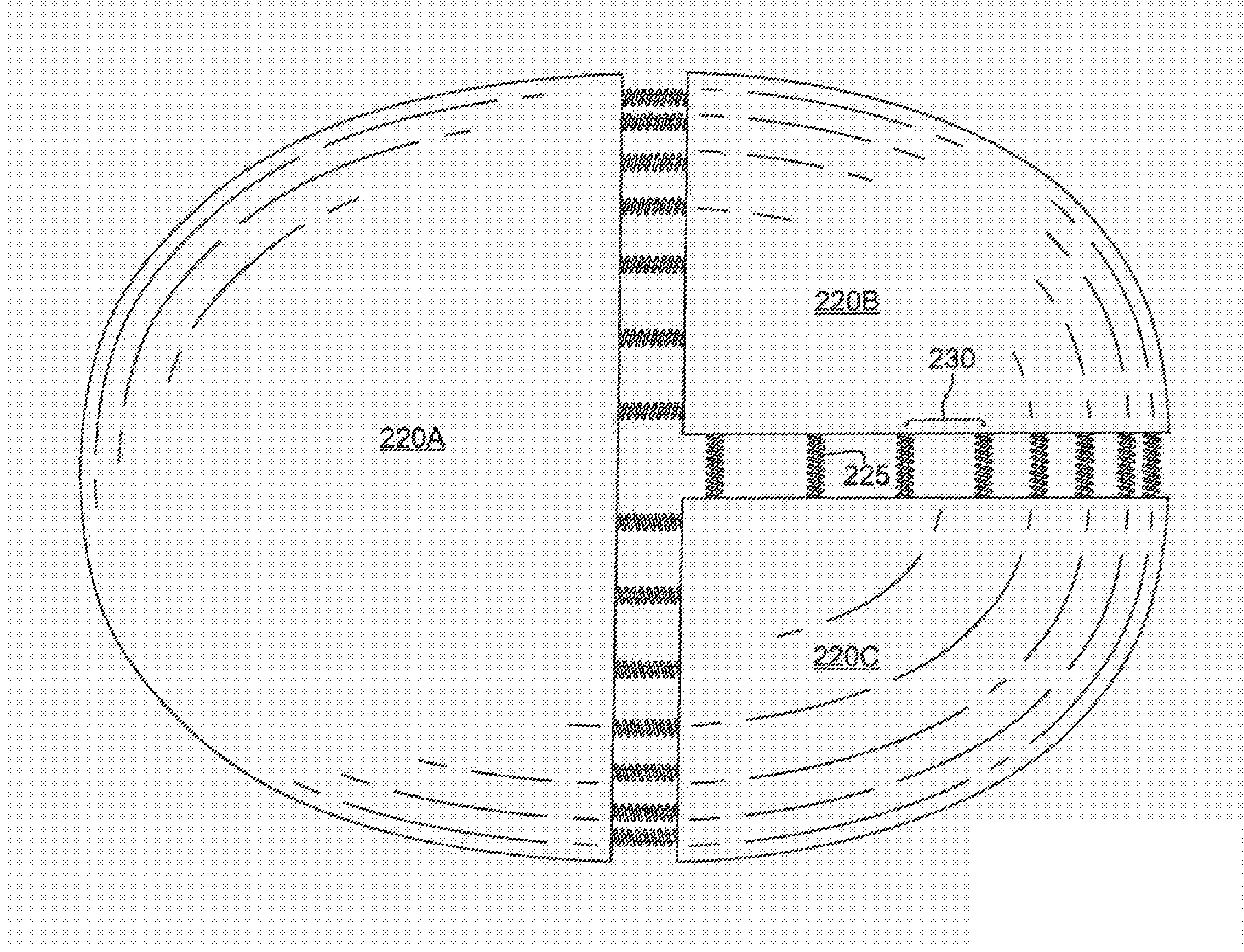
[0042] In a second exemplary embodiment, shown in FIGS. 7 and 8, an alternative manufacture of the first exemplary embodiment is presented. In this second embodiment, more, smaller springs may be utilized and the underside attachment strip anchoring the components is foregone. Instead, the componentry would be engineered into the shell of the helmet itself. When engineered directly into the helmet, the snap-back system could further limit the section connection actor to just the spring itself, displacing the bolt and double nut stop features.
[0043] FIG. 7 is a top view of the second embodiment, with three helmet sections 220A, 220B, and 220C held connected by multiple, closely arrayed 230 springs 225.
[0044] FIG. 8 is an underside view of the second embodiment, wherein springs may be molded and manufactured into the helmet without the need for bolts, nuts, or an attachment strip 235.
[0045] FIGS. 9A and 9B are close-up views of a compression event, in which an external impact causes adjoining helmet sections 240A, 240B to move towards one another 265. In a first embodiment, the anchored 260 snap-back system of spring 245, bolt 250, and nuts 255 would act in unison to disperse and dissipate impact through compression from one helmet section to another, and return to ready for further external impact or to redouble. In a second embodiment, the same outcome could occur through mechanism of a shell-anchored spring acting in isolation.
[0046] In a third exemplary embodiment, shown in FIGS. 10A and 10B, either embodiment detailed above could feature a coating material covering springs along sectional gaps. FIGS. 10A and 10B are close-up views of the compression event of FIG. 9 above, highlighting a compressible material 270, 275 that would be added over the spring array to prevent intrusion by foreign objects.
[0047] In a fourth exemplary embodiment, shown in FIGS. 11A and 11B, either first or second embodiment above could feature a tongue and groove design ideal for both sports and military applications, for instance as a shrapnel guard.
* * * * *
D00000
D00001
D00002
D00003
D00004
D00005
D00006
D00007
D00008
D00009
D00010
XML
uspto.report is an independent third-party trademark research tool that is not affiliated, endorsed, or sponsored by the United States Patent and Trademark Office (USPTO) or any other governmental organization. The information provided by uspto.report is based on publicly available data at the time of writing and is intended for informational purposes only.
While we strive to provide accurate and up-to-date information, we do not guarantee the accuracy, completeness, reliability, or suitability of the information displayed on this site. The use of this site is at your own risk. Any reliance you place on such information is therefore strictly at your own risk.
All official trademark data, including owner information, should be verified by visiting the official USPTO website at www.uspto.gov. This site is not intended to replace professional legal advice and should not be used as a substitute for consulting with a legal professional who is knowledgeable about trademark law.