One Hitter Smoking Apparatus
Levine; Steven Marc
U.S. patent application number 16/024664 was filed with the patent office on 2019-01-03 for one hitter smoking apparatus. The applicant listed for this patent is Steven Marc Levine. Invention is credited to Steven Marc Levine.
| Application Number | 20190000139 16/024664 |
| Document ID | / |
| Family ID | 64734911 |
| Filed Date | 2019-01-03 |


| United States Patent Application | 20190000139 |
| Kind Code | A1 |
| Levine; Steven Marc | January 3, 2019 |
ONE HITTER SMOKING APPARATUS
Abstract
A smoking apparatus includes a tubular member having a loading end, and a rear end, wherein an axial throughbore is formed along a longitudinal axis from the rear end to the loading end of the tubular member defining an axial smoke passage. A plurality of annular grooves are formed in an outer surface of the tubular member that are configured to increase an available surface area for heat transfer. In some embodiments, the tubular member includes a threaded joint connector at the rear end and an annular beveled surface at the loading end having an outer diameter smaller than an outer diameter of the tubular member. A cutting surface is formed at an intersection of the beveled surface and an inner circumferential surface of the loading end of the tubular member.
| Inventors: | Levine; Steven Marc; (Madison, CT) | ||||||||||
| Applicant: |
|
||||||||||
|---|---|---|---|---|---|---|---|---|---|---|---|
| Family ID: | 64734911 | ||||||||||
| Appl. No.: | 16/024664 | ||||||||||
| Filed: | June 29, 2018 |
Related U.S. Patent Documents
| Application Number | Filing Date | Patent Number | ||
|---|---|---|---|---|
| 62527491 | Jun 30, 2017 | |||
| Current U.S. Class: | 1/1 |
| Current CPC Class: | A24F 1/28 20130101 |
| International Class: | A24F 1/28 20060101 A24F001/28 |
Claims
1. A smoking apparatus, comprising: a tubular member having a loading end, and a rear end, wherein an axial throughbore is formed along a longitudinal axis from the rear end to the loading end of the tubular member defining an axial smoke passage; and further wherein a plurality of annular grooves are formed in an outer surface of the tubular member that are configured to increase an available surface area for heat transfer.
2. The apparatus of claim 1, wherein the tubular member comprises a threaded joint connector at the rear end.
3. The apparatus of claim 1, wherein the tubular member comprises an annular beveled surface at the loading end having an outer diameter smaller than an outer diameter of the tubular member.
4. The apparatus of claim 3, wherein a cutting surface is formed at an intersection of the beveled surface and an inner circumferential surface of the loading end of the tubular member.
Description
CROSS REFERENCE TO RELATED APPLICATIONS
[0001] This application is related to U.S. Provisional Patent Application No. 62/527,491 (Attorney Docket No. SLEV001USP), entitled "ONE HITTER SMOKING APPARATUS" and filed on Jun. 30, 2017, the entirety of which is incorporated by reference herein.
BACKGROUND
[0002] Smoking apparatuses include, for example, bongs in which smoke from a substance being combusted (e.g., tobacco, hashish, or another type of herb) is filtered by a liquid before it is inhaled by a user. These smoking apparatuses often include a smoking bowl for receiving the substance being combusted. Smoke from the substance being combusted is directed through an opening that discharges into a container, such as a water base or a vase, below the surface of the liquid to provide the function of liquid-based cooling and cleansing of ash, tars and other contaminants in the smoke. Subsequently, the liquid-filtered smoke passes from a smoke chamber formed above the surface of the liquid to the user via an outlet from the smoking apparatus. The bowl of the smoking apparatuses often requires refilling between repeated usages of the smoking apparatus.
BRIEF DESCRIPTION OF THE DRAWINGS
[0003] The present disclosure may be better understood by, and its numerous features and advantages made apparent to, those skilled in the art by referencing the accompanying drawings. The use of the same reference symbols in different drawings indicates similar or identical items.
[0004] FIGS. 1A-1F are various diagrams illustrating views of an example bat in accordance with at least one embodiment of the present disclosure.
[0005] FIGS. 2A-2F are various diagrams illustrating views of another example bat in accordance with at least one embodiment of the present disclosure.
[0006] FIGS. 3A-3D are various diagrams illustrating views of an example bowl in accordance with at least one embodiment of the present disclosure.
[0007] FIG. 4 is a diagram illustrating an exploded side view of an assembled smoking apparatus using the bat and bowl of FIGS. 1A-3D in accordance with at least one embodiment of the present disclosure.
[0008] FIG. 5 is a diagram illustrating an exploded perspective view of a smoking apparatus using the bat and bowl of FIGS. 1A-3D in accordance with at least one embodiment of the present disclosure.
[0009] FIGS. 6A-6D are various diagrams illustrating views of an example assembled smoking apparatus in accordance with at least one embodiment of the present disclosure.
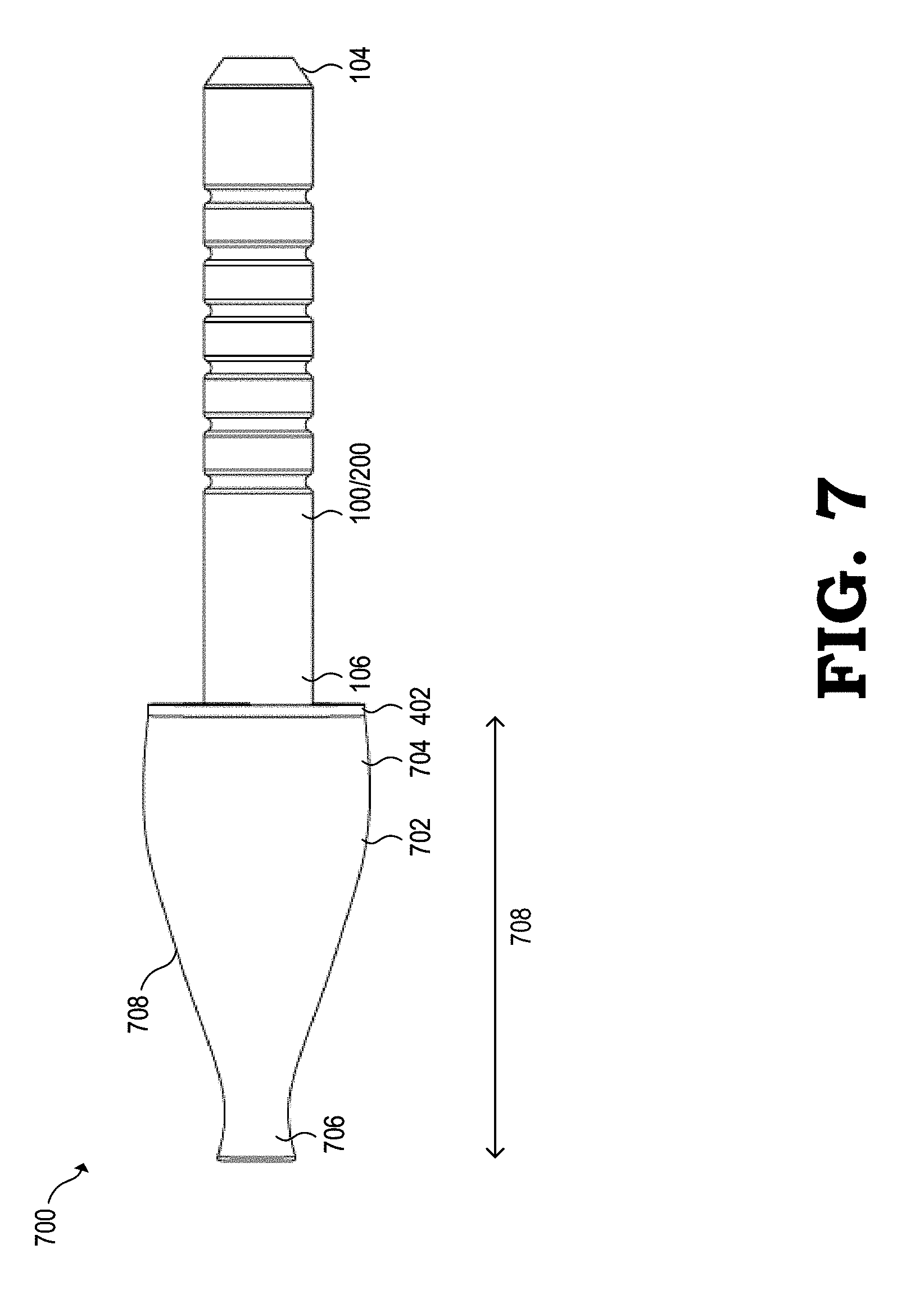
[0010] FIG. 7 is a diagram illustrating a side view of another example assembled smoking apparatus in accordance with at least one embodiment of the present disclosure.
DETAILED DESCRIPTION
[0011] Present day smoking systems include bongs designed to hold a stem and bowl. It is generally cumbersome to load such bowls with smoking material by hand, and do not provide a quick and efficient method to re-fill the bowl with smoking material. Additionally, the dosage (e.g., volume) of smoking material to be loaded into the bowls is often imprecise and varies from one load to another. Further, the large volume of bowls does not lend itself to a single usage dose. Accordingly, it is common to encounter wastage of smoking material due to residual burning of the smoking material inbetween active combustions during smoking. Such residual burning of the smoking material additionally results in the creation of nuisance smoke and odor.
[0012] FIGS. 1A-7 illustrate various illustrations for a one hitter smoking apparatus. In some embodiments, the smoking apparatus includes a tubular member having a loading end, and a rear end, wherein an axial throughbore is formed along a longitudinal axis from the rear end to the loading end of the tubular member defining an axial smoke passage. A plurality of annular grooves are formed in an outer surface of the tubular member that are configured to increase an available surface area for heat transfer. In some embodiments, the tubular member includes a threaded joint connector at the rear end and an annular beveled surface at the loading end having an outer diameter smaller than an outer diameter of the tubular member. A cutting surface is formed at an intersection of the beveled surface and an inner circumferential surface of the loading end of the tubular member.
[0013] FIGS. 1A-1F are various diagrams illustrating views of a bat 100 (which can also be referred to as a pipe) in accordance with at least one embodiment of the present disclosure. FIGS. 1A-1B are diagrams showing side perspective views of the bat 100. In particular, FIG. 1A is a diagram illustrating a side perspective view from a rearward end portion of the bat 100. FIG. 1B is a diagram illustrating a side perspective view from a forward end portion of the bat 100. FIG. 1C is a diagram illustrating a rear elevational view of the bat 100. FIG. 1D is a diagram illustrating a top elevational view of the bat 100. FIG. 1E is a diagram illustrating a cross sectional view of the bat. FIG. 1F is a diagram illustrating a front elevational view of the bat 100.
[0014] In some embodiments, the bat 100 includes a tubular member, which can be made of a material such as a metal alloy, that defines an axial throughbore 102 which extends longitudinally through the body of the tubular member that allows the passage of smoke. Although described here in the context of fabricated from a metal alloy, any other suitable materials may be utilized, including, but not limited to, various glasses, ceramics, borosilicate glass, wood, soapstone, meerschaum, metals, anodized aluminum, and the like. The bat 100 includes a forward or loading end portion 104 and a rearward end portion 106. The axial throughbore 102 extends through the bat 100 from the forward end portion 104 to the rearward end portion 106 along an inner circumferential surface 108 of the bat 100. In the example embodiment of FIGS. 1A-1F, the axial throughbore 102 is concentric with the outer surface 112 of the bat 100 (such as illustrated in FIGS. 1C and 1F). However, in other embodiments, the axial throughbore 102 may be formed as an eccentric bore that provides an opening between the rearward end portion 106 and the forward end portion 104 of the bat 100. The eccentric bore may share a common longitudinal axis with the body of the bat 100, but does not necessarily have to share the same lateral and/or vertical axis.
[0015] The loading end portion 104 of the bat 100 includes an annular beveled surface 110 that extends between the outer surface 112 of the bat 100 and a reduced outer diameter portion 114 of the loading end portion 104. The annular beveled surface 110 extends, in one embodiment, at an angle of about 45 degrees relative to the longitudinal axis of the bat 100. A cutting surface 116 is formed at the intersection of the beveled surface 110 and an inner circumferential surface 118 of the loading end portion 104 of the bat 100. Further, a concavity is formed at the loading end portion 104 so as to form a loading chamber 120 (which may also be referred to as a bowl). In some embodiments, the cutting surface 116 is configured for insertion into a supply of smoking material to be combusted. A rotary twist and/or pressing of the cutting surface 116 against the supply of substance to be combusted performs a cutting action such that a loading chamber 120 of the bat 100 will be filled with a smoking material (e.g., a ground combustible such as tobacco, marijuana, or other substance to be combusted). In the examples of FIGS. 1A-1F, the loading chamber 120 has a diameter greater than that of the axial throughbore 102. In other embodiments, the loading chamber 120 have a diameter smaller than that of the axial throughbore 102 or a diameter equal to that of the axial through bore 102 (i.e., a unitary bore from the loading end portion 104 to the rearward end portion 106).
[0016] In some embodiments, the bat 100 includes a plurality of heat sinks 122 formed as annular grooves (e.g., generally inward indentations) in the outer surface 112 of the bat 100. The annular grooves are configured to increase the outer surface area of the bat 100 for heat transfer and serve to operate as heat sinks. As illustrated, the heat sinks 122 are positioned distal from the intersection of the beveled surface 110 and the outer surface 112 of the bat 100. For example, in some embodiments, the heat sinks 122 begin at a distance of half an inch away from the intersection of the beveled surface 110 and the outer surface 112 of the bat 100. This offset distance prevents smoking material intended for the loading chamber 120 from being unintentionally lodged within the annular grooves of the heat sink. In various embodiments, the offset distance may be varied to provide the benefit of heat dissipation from the heat sinks 122 that are positioned far enough away such that when the loading end portion 104 of the bat 100 is inserted into a container containing smoking material, the smoking material does not reach and become lodged within the annular grooves.
[0017] Although the heat sinks 122, as illustrated in FIGS. 1A-1F, include annular grooves extending radially around the bat 100, other configurations can be used without departing from the scope of this disclosure. For example, in some embodiments, the heat sinks can be formed as grooves axially aligned along the length of the bat 100. In other embodiments, the heat sinks can be formed as half-spherical indentations along the outer surface 112. Alternatively, in various other embodiments, the heat sinks can be formed in any other manner that increases available surface area for heat transfer as is generally known to those skilled in the art. Further, in other embodiments, the bat 100 may alternatively be formed without any heat sinks along the external circumferential surface of the bat 100.
[0018] In some embodiments, the bat 100 includes a suitable connection mechanism, such as the threaded configuration as illustrated in FIGS. 1A-1F, to connect the bat 100 to adjacent components of a smoking apparatus. For example, bat 100 as illustrated includes a threaded joint connection 124. In an example embodiment, the bat 100 is approximately three and one-quarter inches long and has an outer diameter of approximately three-eighths of an inch. A one-eighth inch opening is centered at the rearward end portion 106 of the bat 100, extends through the entirety of the bat 100, and exits at the forward end portion 104 to form the axial throughbore 102. A concavity is formed at the forward end portion 104 so as to form the loading chamber 120. Generally, the loading chamber 120 has a diameter between that of the outer diameter of the bat 100 and the diameter of the axial throughbore 102. In one embodiment, the inside diameter of the loading chamber 120 can be approximately three-sixteenths of an inch with an axial depth of one-fifth of an inch. The threaded joint connection 124 is a male 1/8 iron pipe straight (IPS) thread. Further, the threaded joint connection 124 has dimensions of approximately 27 threads per inch (TPI). The heat sinks 122 are both 0.06 inches wide and deep for each annular groove. However, those skilled in the art will recognize that various connection mechanisms and apparatus dimensions can be used without departing from the scope of this disclosure.
[0019] It is to be recognized that bat 100 is merely exemplary in nature and various additional components can be present that have not necessarily been depicted in FIGS. 1A-1F in the interest of clarity. Non-limiting additional components that can be present include, but are not limited to bowls, down-stems, slides, diffusers, coolers, pre-coolers, ash catchers, carbon filters, clips, percolators, keck clips, seals, stems, vases, tubes, filters, baffles, dampers, other smoking devices or components, and the like. Any of these components can be included in a smoking apparatus incorporation the bat 100 generally described above and depicted in FIGS. 1A-1F; however, the bat 100 is not limited to the example implementations discussed herein.
[0020] FIGS. 2A-2F are various diagrams illustrating views of a bat 200 (which can also be referred to as a pipe) in accordance with at least one embodiment of the present disclosure. FIGS. 2A-2B are diagrams showing side perspective views of the bat 200. In particular, FIG. 2A is a diagram illustrating a side perspective view from a rearward end portion of the bat 200. FIG. 2B is a diagram illustrating a side perspective view from a forward end portion of the bat 200. FIG. 2C is a diagram illustrating a rear elevational view of the bat 200. FIG. 2D is a diagram illustrating a top elevational view of the bat 200. FIG. 2E is a diagram illustrating a cross sectional view of the bat. FIG. 2F is a diagram illustrating a front elevational view of the bat 200.
[0021] In some embodiments, the bat 200 includes a tubular member, which can be made of a material such as a metal alloy, that defines an axial throughbore 202 which extends longitudinally through the body of the tubular member that allows the passage of smoke. Although described here in the context of fabricated from a metal alloy, any other suitable materials may be utilized, including, but not limited to, various glasses, ceramics, borosilicate glass, wood, soapstone, meerschaum, metals, anodized aluminum, and the like. The bat 200 includes a forward or loading end portion 204 and a rearward end portion 206. The axial throughbore 202 extends through the bat 200 from the forward end portion 204 to the rearward end portion 206 along an inner circumferential surface 208 of the bat 200. In the example embodiment of FIGS. 2A-2F, the axial throughbore 202 is concentric with the outer surface 212 of the bat 200 (such as illustrated in FIGS. 2C and 2F). However, in other embodiments, the axial throughbore 202 may be formed as an eccentric bore that provides an opening between the rearward end portion 206 and the forward end portion 204 of the bat 200. The eccentric bore may share a common longitudinal axis with the body of the bat 200, but does not necessarily have to share the same lateral and/or vertical axis.
[0022] The loading end portion 204 of the bat 200 includes an annular beveled surface 210 that extends between the outer surface 212 of the bat 200 and a reduced outer diameter portion 214 of the loading end portion 204. The annular beveled surface 210 extends, in one embodiment, at an angle of about 45 degrees relative to the longitudinal axis of the bat 200. A cutting surface 216 is formed at the intersection of the beveled surface 210 and an inner circumferential surface 218 of the loading end portion 204 of the bat 200. Further, a concavity is formed at the loading end portion 204 so as to form a loading chamber 220 therein. In some embodiments, the cutting surface 216 is configured for insertion into a supply of smoking material to be combusted. A rotary twist and/or pressing of the cutting surface 216 against the supply of substance to be combusted performs a cutting action such that a loading chamber 220 of the bat 200 will be filled with a smoking material (e.g., tobacco, marijuana, or other substance to be combusted). In the examples of FIGS. 2A-2F, the loading chamber 220 has a diameter greater than that of the axial throughbore 202. In other embodiments, the loading chamber 220 have a diameter smaller than that of the axial throughbore 202 or a diameter equal to that of the axial through bore 202 (i.e., a unitary bore from the loading end portion 204 to the rearward end portion 206).
[0023] In some embodiments, the bat 200 includes a plurality of heat sinks 222 formed as annular grooves (e.g., generally inward indentations) in the outer surface 212 of the bat 200. The annular grooves are configured to increase the outer surface area of the bat 200 for heat transfer and serve to operate as heat sinks. Although the heat sinks 222, as illustrated in FIGS. 2A-2F, include annular grooves extending radially around the bat 200, other configurations can be used without departing from the scope of this disclosure. For example, in some embodiments, the heat sinks can be formed as grooves axially aligned along the length of the bat 200. In other embodiments, the heat sinks can be formed as half-spherical indentations along the outer surface 212. Alternatively, in various other embodiments, the heat sinks can be formed in any other manner that increases available surface area for heat transfer as is generally known to those skilled in the art.
[0024] In some embodiments, the bat 200 includes a suitable connection mechanism, such as the threaded configuration as illustrated in FIGS. 2A-2F, to connect the bat 200 to adjacent components of a smoking apparatus. For example, bat 200 as illustrated includes a threaded joint connection 224. In an example embodiment, the bat 200 is approximately three and one-quarter inches long and has an outer diameter of approximately three-eighths of an inch. A one-eighth inch opening is centered at the rearward end portion 206 of, extends through the entirety of the bat 200, and exits at the forward end portion 204 to form the axial throughbore 202. A concavity is formed at the forward end portion 204 so as to form the loading chamber 220. Generally, the loading chamber 220 has a diameter between that of the outer diameter of the bat 200 and the diameter of the axial throughbore 202. In one embodiment, the inside diameter of the loading chamber 220 can be approximately three-sixteenths of an inch with an axial depth of one-fifth of an inch. The threaded joint connection 224 is a male 1/8 iron pipe straight (IPS) thread. Further, the threaded joint connection 224 has dimensions of approximately 27 threads per inch (TPI). The heat sinks 222 are both 0.06 inches wide and deep for each annular groove. However, those skilled in the art will recognize that various connection mechanisms and apparatus dimensions can be used without departing from the scope of this disclosure.
[0025] It is to be recognized that bat 200 is merely exemplary in nature and various additional components can be present that have not necessarily been depicted in FIGS. 2A-2F in the interest of clarity. Non-limiting additional components that can be present include, but are not limited to bowls, down-stems, slides, diffusers, coolers, pre-coolers, ash catchers, carbon filters, clips, percolators, keck clips, seals, stems, vases, tubes, filters, other smoking devices or components, and the like. Any of these components can be included in a smoking apparatus incorporation the bat 200 generally described above and depicted in FIGS. 2A-2F; however, the bat 200 is not limited to the example implementations discussed herein.
[0026] FIGS. 3A-3D are various diagrams illustrating views of a bowl 300 in accordance with at least one embodiment of the present disclosure. FIG. 3A is a diagram illustrating a side perspective view of the bowl 300. FIG. 3B is a diagram illustrating a top elevational view of the bowl 300. FIG. 3C is a diagram illustrating a cross sectional view of the bowl 300. FIG. 3D is a diagram illustrating a bottom elevational view of the bowl 300.
[0027] In some embodiments, the bowl 300 at least partially includes a tubular member, which can be made of a material such as a metal alloy, having an axial throughbore 302 which extends longitudinally through at least a portion of the body of the tubular member to allow the passage of smoke. Although described here in the context of fabricated from a metal alloy, any other suitable materials may be utilized, including, but not limited to, various glasses, borosilicate glass, wood, soapstone, meerschaum, metals, anodized aluminum, and the like. The bowl 300 includes a top end 304 and a bottom end 306. The axial throughbore 302 extends through the bowl from the top end 304 to the bottom end 306. Further, in various embodiments, a concavity is formed in at least a portion of the top end 304 so as to form a bore area 308 as defined by an inner threaded circumferential surface 310 having a diameter greater than that of the axial throughbore 302. The bore area 308, the inner threaded circumferential surface 310, and an outer surface 312 define an annular portion 314 of the bowl 300.
[0028] In the example embodiment of FIGS. 3A-3D, both the axial throughbore 302 and bore area 308 are concentric with the outer surface 312 of the bowl 300 (such as illustrated in FIGS. 3B-3C). However, in other embodiments, any of the axial throughbore 302 and bore area 308 may be formed as eccentric bores that provides an opening between the top end 304 and the bottom end 306 of the bowl 300. The eccentric bore may share a common longitudinal axis with the body of the bowl 300, but does not necessarily have to share the same lateral and/or vertical axis.
[0029] As illustrated, the axial throughbore 302 extends through the bowl 300 from the bowl from the bottom end 306 to the bore area 308 along an inner circumferential surface 316 of the bowl 300. In some embodiments, the diameter of the axial throughbore 302 is smaller than the diameter of the bore area 308 (e.g., the axial throughbore 302 and bore area 308 are concentric relative to each other). Accordingly, the interior portion of the bowl 300 includes an annular beveled interior surface 318 that extends between the inner threaded circumferential surface 310 of the bore area 308 and the inner circumferential surface 316 of the axial throughbore 302. The annular beveled interior surface 318 extends, in one embodiment, at an angle of about 45 degrees relative to the longitudinal axis of the bowl 300. Although the examples of FIGS. 3A-3D depict an embodiment in which the diameter of the axial throughbore 302 is smaller than the diameter of the bore area 308, the diameter of the axial throughbore 302 may alternatively have a diameter larger than that of the bore area 308 or a diameter equal to that of the bore area 308. Accordingly, the annular beveled interior surface 318 would not be present in embodiments for which the diameter of the axial throughbore 302 has a diameter equal to that of the bore area 308.
[0030] In various embodiments, the bowl 300 also includes one or more suitable connection mechanisms, such as the threaded configuration as illustrated in FIGS. 3A, 3C, and 3D, to connect the bowl 300 to adjacent components of a smoking apparatus (e.g., pipe stem such as discussed below relative to FIG. 4). For example, the bottom end 306 of bowl 300 as illustrated includes a threaded joint connection 320. In an example embodiment, the threaded joint connection 320 has an outer diameter of approximately three-eighths of an inch. A one-eighth inch opening is centered at the threaded joint connection 320 of the bottom end 306 that extends through the entirety of the bowl 300, and exits at the top end 304 to form the axial throughbore 302. The threaded joint connection 320 is a male 1/8 iron pipe straight (IPS) thread. Further, the threaded joint connection 320 has dimensions of approximately 27 threads per inch (TPI). However, those skilled in the art will recognize that various connection mechanisms and apparatus dimensions can be used without departing from the scope of this disclosure.
[0031] FIG. 4 is a diagram illustrating an exploded side view of a smoking apparatus 400 in accordance with at least one embodiment of the present disclosure. FIG. 5 is a diagram illustrating an exploded perspective view 500 of the smoking apparatus 400 in accordance with at least one embodiment of the present disclosure. As illustrated, the assembled smoking apparatus 400 includes the bat 100 (or alternatively, the bat 200 of FIG. 2) coupleable at its rearward end portion 106 to bowl 300 via a reducer 402. As shown, the reducer 402 includes a first end with a female, threaded joint connection 404 configured to be coupled to the male, threaded joint connection 124 of the bat 100. Additionally, the reducer 402 includes a second end with a male, threaded joint connection 406 configured to be coupled to the female, inner threaded circumferential surface 310 of the bore area 308 of the bowl 300. It will be appreciated that the reducer 402 allows for the bat 100 having a smaller diameter to be connected to the bowl 300, which generally has a larger diameter than the bat 100.
[0032] Further, the assembled smoking apparatus 400 includes a filter screen 408 configured to be positioned within the bore area 308 of the bowl 300, which provides for the filtering of particulates from smoke produced by the combustion of smoking material at the loading end portion 104 of the bat 100. In some embodiments, the filter screen 408 is a screen mesh (e.g., a 3/4'' screen) with variable dimensions for accommodating to user preference. For example, the filter screen 408 may have opening dimensions of 60.times.60, 100.times.100, 150.times.150 (representing openings per square inch), or any other opening dimension to account for varying user preference for taste and particulate capture.
[0033] Additionally, the assembled smoking apparatus 400 includes the bowl 300 coupled to, for example, a pipe stem 412 (also known as a down stem). For example, in various embodiments, the male, threaded joint connection 320 of the bat 300 may be coupled to a female, threaded joint connection 414 of the pipe stem 412. The pipe stem 412 is a tubular member, which can be made of a material such as a metal alloy, that defines an axial throughbore which extends longitudinally through the body of the tubular member that allows the passage of smoke. Although described here in the context of fabricated from a metal alloy, any other suitable materials may be utilized, including, but not limited to, various glasses, ceramics, borosilicate glass, wood, soapstone, meerschaum, metals, anodized aluminum, and the like. The axial throughbore extends through the pipe stem 412 from the forward end portion 416 to the rearward end portion 418 along an inner circumferential surface of the pipe stem 412. In various embodiments, the axial throughbore of the pipe stem 412 is concentric with the outer surface 420 of the pipe stem 412. However, in other embodiments, the axial throughbore of the pipe stem 412 may be formed as an eccentric bore that provides an opening between the rearward end portion 418 and the forward end portion 416. The eccentric bore may share a common longitudinal axis with the body of the pipe stem 412, but does not necessarily have to share the same lateral and/or vertical axis.
[0034] Accordingly, when the bat 100, the reducer 402, the bowl 300, and the pipe stem 412 are coupled together, the smoking apparatus 400 includes an axial throughbore that extends from the rearward end portion 418 of the pipe stem 412 to the loading end portion 104 of the bat 100. In various embodiments, the smoking apparatus 400 may be inserted into, for example, a bong (not shown) as is generally known in the art. It will be appreciated that the variable dimensions of the bottom end 306 of the bowl 300 forms a variable size seal to the bong when pipe stem 412 is inserted into the stem of the bong. That is, any of the varying diameters of different portions of the outer circumferential surfaces of the bowl 300 and the forward end portion 416 of the pipe stem 412 can match the internal circumferential surface of the bong stem to provide a substantially air-tight seal to minimize wastage due to smoke loss. Additionally, as described herein, the smoking apparatus 400 includes a concavity (e.g., loading chamber 120 of FIG. 1) formed at the loading end portion 104 that allows for a repeatable, pre-determined dosage of smoking material to be loaded for combustion. Further, the smaller volume of the loading chamber 120 relative to, for example, the concavity of bowls (e.g., bore area 308) enables decreases in waste of smoking material lost to residual burning inbetween active usages of the smoking apparatus 400 during smoking operations.
[0035] FIG. 6A is a diagram illustrating a side view of an assembled smoking apparatus 600 in accordance with at least one embodiment of the present disclosure. FIG. 6B is a side perspective view of the assembled smoking apparatus 600 in accordance with at least one embodiment of the present disclosure. As illustrated, the assembled smoking apparatus 600 includes the bat 100 (or alternatively, the bat 200 of FIG. 2) coupleable at its rearward end portion 106 to adapter 602 via the reducer 402 (such as previously described relative to FIG. 4). The reducer 402 includes a first end with a female, threaded joint connection (not shown) configured to be coupled to the male, threaded joint connection (not shown) of the bat 100. Additionally, the reducer 402 includes a second end with a male, threaded joint connection (not shown) configured to be coupled to the female, inner threaded circumferential surface (not shown) of the bore area of the adapter 602. It will be appreciated that the reducer 402 allows for the bat 100 having a smaller diameter to be connected to the adapter 602, which generally has a larger diameter than the bat 100. Additionally, in some embodiments, the assembled smoking apparatus 600 optionally includes a mouth piece 604 coupled to the adapter 602 that allows for smoking use of the assembled smoking apparatus 600 without insertion into, for example, a bong.
[0036] FIG. 6C is a side view of the adapter 602 in accordance with at least one embodiment of the present disclosure. In various embodiments, the male threaded joint connection 406 of the reducer 402 (such as illustrated and described above relative to FIG. 4) is configured to be coupled to a female, inner threaded circumferential surface (not shown) of the bore area (not shown) of the adapter 602 (in a manner similar to that of bowl 300 as illustrated and described above relative to FIG. 4). The adapter 602 is a tubular member, which can be made of a material such as a metal alloy, that defines an axial throughbore 606 which extends longitudinally through the body of the tubular member that allows the passage of smoke. Although described here in the context of fabricated from a metal alloy, any other suitable materials may be utilized, including, but not limited to, various glasses, ceramics, borosilicate glass, wood, soapstone, meerschaum, metals, anodized aluminum, and the like. The axial throughbore 606 extends through the adapter 602 from the forward end portion 608 to the rearward end portion 610 along an inner circumferential surface 612 of the adapter 602. In various embodiments, the axial throughbore 606 of the adapter 602 is concentric with the outer surface(s) of the adapter 602. However, in other embodiments, the axial throughbore 606 of the adapter 602 may be formed as an eccentric bore that provides an opening between the rearward end portion 610 and the forward end portion 608. The eccentric bore may share a common longitudinal axis with the body of the adapter 602, but does not necessarily have to share the same lateral and/or vertical axis.
[0037] As illustrated, the adapter 602 includes a plurality of outer surface portions 614 (e.g., outer surface portions 614a, 614b, 614c, and 614d) in which each outer surface portion has different outer diameters relative to the other outer surface portions 614. For example, the outer surface portion 614a, which is closest to the forward end portion 608 of the adapter 602, extends for a first portion of the longitudinal length 616 of the adapter 602 and has an outer diameter greater than the adjacent outer surface portion 614b. Similarly, the outer surface portion 614b extends along a second portion of the longitudinal length 616 of the adapter 602 and has an outer diameter greater than the adjacent outer surface portion 614c. The outer surface portion 614d, which is closest to the rearward end portion 610 of the adapter 602, extends for a fourth portion of the longitudinal length 616 of the adapter 602 and has an outer diameter lesser than the adjacent outer surface portion 614c.
[0038] Accordingly, when the bat 100, the reducer 402, and the adapter 602, are coupled together, the smoking apparatus 600 includes an axial throughbore that extends from the rearward end portion 610 of the adapter 602 to the loading end portion 104 of the bat 100. In various embodiments, the smoking apparatus 600 may be inserted into, for example, a bong (not shown) as is generally known in the art. It will be appreciated that the variable dimensions of the plurality of outer surface portions 614 of the adapter 602 provide a variable size seal to the bong when adapter 602 of the smoking apparatus 600 is inserted into the stem of the bong. That is, any of the varying diameters of the different outer surface portions 614 of the adapter 602 (e.g., outer circumferential surfaces of the adapter 602) can match the internal circumferential surface of the bong stem to provide a substantially air-tight seal to reduce wastage due to smoke loss.
[0039] Optionally, such as illustrated in FIG. 6D, a mouthpiece 604 is coupleable to the rearward end portion 610 of the adapter 602 to allow for smoking use of the assembled smoking apparatus 600 (as illustrated in FIGS. 6A-6B) without insertion into, for example, a bong. In some embodiments, an internal circumferential surface (not shown) of the mouth piece 604 is slidably fitted over a portion of the outer surface of the adapter 602 to couple the mouth piece 604 to the adapter 602. As illustrated, in FIGS. 6A-6B, the internal circumferential surface (not shown) of the mouth piece 604 slidably fits over the outer surface portion 614d and thus forms an axial throughbore that extends from the rearward end portion 614 of the mouth piece 604 to the loading end portion 104 of the bat 100. In other embodiments, a portion of the rearward end portion 610 of the adapter 602 includes another suitable connection mechanism, such as the various threaded configurations discussed herein, to the couple the mouth piece 604 to the adapter 602.
[0040] In some embodiments, the assembled smoking apparatus 600 includes a filter screen (such as filter screen 408 of FIG. 4) configured to be positioned within the bore area of the adapter 602, which provides for the filtering of particulates from smoke produced by the combustion of smoking material at the loading end portion 104 of the bat 100. In some embodiments, the filter screen is a screen mesh (e.g., a 3/4'' screen) with variable dimensions for accommodating to user preference. For example, the filter screen may have opening dimensions of 60.times.60, 100.times.100, 150.times.150 (representing openings per square inch), or any other opening dimension to account for varying user preference for taste and particulate capture.
[0041] Although described here in the context of a adapter 602 have four outer surface portions 614 of differing diameters, those skilled in the art will recognize that a adapter 602 having any number of outer surface portions of differing diameters may be used without departing from the scope of this disclosure. For example, in some embodiments, the adapter 602 includes three or fewer outer surface portions of differing diameters. In other embodiments, the adapter 602 includes five or more outer surface portions of differing diameters. In yet another embodiment, such as discussed below relative to FIG. 7, the bowl includes an outer surface that gradually changes in outer diameter dimensions along its longitudinal length.
[0042] FIG. 7 is a diagram illustrating a side view of an assembled smoking apparatus 700 in accordance with at least one embodiment of the present disclosure. As illustrated, the assembled smoking apparatus 700 includes the bat 100 (or alternatively, the bat 200 of FIG. 2) coupleable at its rearward end portion 106 to adapter 702 via a reducer 402 (such as previously described relative to FIG. 4). The reducer 402 includes a first end with a female, threaded joint connection (not shown) configured to be coupled to the male, threaded joint connection (not shown) of the bat 100. Additionally, the reducer 402 includes a second end with a male, threaded joint connection (not shown) configured to be coupled to the female, inner threaded circumferential surface (not shown) of the bore area of the adapter 702. It will be appreciated that the reducer 402 allows for the bat 100 having a smaller diameter to be connected to the adapter 702, which generally has a larger diameter than the bat 100.
[0043] In various embodiments, the male threaded joint connection (not shown) of the reducer 402 (such as illustrated and described above relative to FIG. 4) is configured to be coupled to a female, inner threaded circumferential surface (not shown) of the bore area (not shown) of the adapter 702 (in a manner similar to that of bowl 300 as illustrated and described above relative to FIG. 4). The adapter 702 is a tubular member, which can be made of a material such as a metal alloy, that defines an axial throughbore which extends longitudinally through the body of the tubular member that allows the passage of smoke. Although described here in the context of fabricated from a metal alloy, any other suitable materials may be utilized, including, but not limited to, various glasses, ceramics, borosilicate glass, wood, soapstone, meerschaum, metals, anodized aluminum, and the like. The axial throughbore extends through the adapter 702 from the forward end portion 704 to the rearward end portion 706 along an inner circumferential surface (not shown) of the adapter 702. In various embodiments, the axial throughbore of the adapter 702 is concentric with the outer surface(s) of the adapter 702. However, in other embodiments, the axial throughbore of the adapter 702 may be formed as an eccentric bore that provides an opening between the rearward end portion 706 and the forward end portion 704. The eccentric bore may share a common longitudinal axis with the body of the adapter 702, but does not necessarily have to share the same lateral and/or vertical axis.
[0044] As illustrated, the adapter 702 includes an outer surface 708 that tapers in outer diameter such that the adapter 702 gradually changes in outer diameter dimensions along its longitudinal length 710. As shown, portions of the outer surface 708 proximate to the forward end portion 704 of the adapter 702 generally have dimensions larger than portions of the outer surface 708 proximate to the rearward end portion 706 of the adapter 702. Accordingly, when the bat 100, the reducer 402, and the adapter 702, are coupled together, the smoking apparatus 700 includes an axial throughbore that extends from the rearward end portion 706 of the adapter 702 to the loading end portion 104 of the bat 100. In various embodiments, the smoking apparatus 700 may be inserted into, for example, a bong (not shown) as is generally known in the art. It will be appreciated that the variable dimensions of the plurality of outer surface 708 of the adapter 702 provide a variable size seal to the bong when adapter 702 of the smoking apparatus 700 is inserted into the stem of the bong. That is, any of the varying diameters of the different outer surface portions of the adapter 702 (e.g., outer surface 708) can match the internal circumferential surface of the bong stem to provide a substantially air-tight seal to reduce wastage due to smoke loss. Further, due to the decreased outer diameter at the rearward end portion 706 of the adapter 702, the assembled smoking apparatus 700 allows for smoking use without insertion into, for example, a bong.
[0045] In some embodiments, the assembled smoking apparatus 700 includes a filter screen (such as filter screen 408 of FIG. 4) configured to be positioned within the bore area of the adapter 702, which provides for the filtering of particulates from smoke produced by the combustion of smoking material at the loading end portion 104 of the bat 100. In some embodiments, the filter screen is a screen mesh (e.g., a 3/4'' screen) with variable dimensions for accommodating to user preference. For example, the filter screen may have opening dimensions of 60.times.60, 100.times.100, 150.times.150 (representing openings per square inch), or any other opening dimension to account for varying user preference for taste and particulate capture.
[0046] In this document, relational terms such as first and second, and the like, may be used solely to distinguish one entity or action from another entity or action without necessarily requiring or implying any actual such relationship or order between such entities or actions. The terms "comprises," "comprising," or any other variation thereof, are intended to cover a non-exclusive inclusion, such that a process, method, article, or apparatus that comprises a list of elements does not include only those elements but may include other elements not expressly listed or inherent to such process, method, article, or apparatus. An element preceded by "comprises . . . a" does not, without more constraints, preclude the existence of additional identical elements in the process, method, article, or apparatus that comprises the element. The term "another", as used herein, is defined as at least a second or more. The terms "including" and/or "having", as used herein, are defined as comprising. The term "coupled", as used herein with reference to electro-optical technology, is defined as connected, although not necessarily directly, and not necessarily mechanically. The term "program", as used herein, is defined as a sequence of instructions designed for execution on a computer system. A "program", or "computer program", may include a subroutine, a function, a procedure, an object method, an object implementation, an executable application, an applet, a servlet, a source code, an object code, a shared library/dynamic load library and/or other sequence of instructions designed for execution on a computer system.
[0047] The specification and drawings should be considered as examples only, and the scope of the disclosure is accordingly intended to be limited only by the following claims and equivalents thereof. Note that not all of the activities or elements described above in the general description are required, that a portion of a specific activity or device may not be required, and that one or more further activities may be performed, or elements included, in addition to those described. Still further, the order in which activities are listed are not necessarily the order in which they are performed. The steps of the flowcharts depicted above can be in any order unless specified otherwise, and steps may be eliminated, repeated, and/or added, depending on the implementation. Also, the concepts have been described with reference to specific embodiments. However, one of ordinary skill in the art appreciates that various modifications and changes can be made without departing from the scope of the present disclosure as set forth in the claims below. Accordingly, the specification and figures are to be regarded in an illustrative rather than a restrictive sense, and all such modifications are intended to be included within the scope of the present disclosure.
[0048] Benefits, other advantages, and solutions to problems have been described above with regard to specific embodiments. However, the benefits, advantages, solutions to problems, and any feature(s) that may cause any benefit, advantage, or solution to occur or become more pronounced are not to be construed as a critical, required, or essential feature of any or all the claims.
* * * * *
D00000
D00001
D00002
D00003
D00004
D00005
D00006
XML
uspto.report is an independent third-party trademark research tool that is not affiliated, endorsed, or sponsored by the United States Patent and Trademark Office (USPTO) or any other governmental organization. The information provided by uspto.report is based on publicly available data at the time of writing and is intended for informational purposes only.
While we strive to provide accurate and up-to-date information, we do not guarantee the accuracy, completeness, reliability, or suitability of the information displayed on this site. The use of this site is at your own risk. Any reliance you place on such information is therefore strictly at your own risk.
All official trademark data, including owner information, should be verified by visiting the official USPTO website at www.uspto.gov. This site is not intended to replace professional legal advice and should not be used as a substitute for consulting with a legal professional who is knowledgeable about trademark law.