Composite Web and Method of Manufacturing a Smoking Article
PARK; Kie Seon ; et al.
U.S. patent application number 15/559226 was filed with the patent office on 2019-01-03 for composite web and method of manufacturing a smoking article. The applicant listed for this patent is British American Tobacco (Investments) Limited. Invention is credited to Gary FALLON, Kie Seon PARK.
| Application Number | 20190000133 15/559226 |
| Document ID | / |
| Family ID | 53178415 |
| Filed Date | 2019-01-03 |


| United States Patent Application | 20190000133 |
| Kind Code | A1 |
| PARK; Kie Seon ; et al. | January 3, 2019 |
Composite Web and Method of Manufacturing a Smoking Article
Abstract
The present invention relates to composite web for forming a smoking article element wrapper. The composite web comprises a strip of wrapping material and a plurality of thermally conductive patches. The thermally conductive patches are located on a surface of the strip and are spaced along the length of the strip. The present invention also relates to a method of manufacturing a smoking article component.
| Inventors: | PARK; Kie Seon; (London, GB) ; FALLON; Gary; (London, GB) | ||||||||||
| Applicant: |
|
||||||||||
|---|---|---|---|---|---|---|---|---|---|---|---|
| Family ID: | 53178415 | ||||||||||
| Appl. No.: | 15/559226 | ||||||||||
| Filed: | February 23, 2016 | ||||||||||
| PCT Filed: | February 23, 2016 | ||||||||||
| PCT NO: | PCT/GB2016/050450 | ||||||||||
| 371 Date: | September 18, 2017 |
| Current U.S. Class: | 1/1 |
| Current CPC Class: | A24D 1/025 20130101; A24D 3/0291 20130101; A24D 1/02 20130101; A24D 3/0266 20130101 |
| International Class: | A24D 1/02 20060101 A24D001/02; A24D 3/02 20060101 A24D003/02 |
Foreign Application Data
| Date | Code | Application Number |
|---|---|---|
| Mar 31, 2015 | GB | 1505515.5 |
Claims
1. A composite web for forming a smoking article element wrapper, comprising a strip of wrapping material and a plurality of thermally conductive patches that are located on a surface of the strip and are spaced along the length of the strip, wherein a first edge of each thermally conductive patch is spaced from an adjacent first longitudinal edge of the strip to define a region of the surface of the strip that is not covered by the thermally conductive patches.
2. A composite web according to claim 1, wherein the first edge of each thermally conductive patch is spaced from the first longitudinal edge of the strip by between 1-10 mm and.
3. A composite web according to claim 1, wherein a second edge of each thermally conductive patch overlies an adjacent second longitudinal edge of the strip.
4. A composite web according to claim 1, wherein the thermally conductive patches are adhered and/or laminated to the strip.
5. A composite web according to claim 1, wherein the strip of wrapping material comprises paper.
6. A composite web according to claim 1, wherein the thermally conductive patches comprise metal foil or metalized paper.
7. A method of manufacturing first and second smoking article components comprising first and second smoking article elements respectively, the method comprising the steps of: providing a composite web comprising a strip of wrapping material and a thermally conductive patch located on a surface of the strip; providing first and second smoking article elements on the composite web such that the smoking article elements overlap a first thermally conductive patch of the composite web and are axially spaced to extend axially past opposite edges of the first thermally conductive patch; wrapping the composite web around the smoking article elements; and, cutting the composite web to form a tubular structure that comprises the smoking article elements and the portion of the composite web that circumscribes the smoking article elements.
8. A method according to claim 7, wherein the composite web comprises a plurality of thermally conductive patches that are located on a surface of the strip and are spaced along the length of the strip, and the step of providing first and second smoking article elements on the composite web comprises providing a plurality of rods of smoking article element material on the composite web such that distal ends of each rod overlie adjacent thermally conductive patches of the composite web.
9. A method according to claim 8, wherein the step of cutting the composite web to form the tubular structure further comprises cutting one of the rods of smoking article element material in half such that one half thereof forms the first or second smoking article element of the tubular structure.
10. A method according to claim 8, wherein the step of cutting the composite web to form the tubular structure comprises cutting the composite web such that said portion of the composite web circumscribes the first and second smoking article elements and at least one rod of smoking article element material that is disposed between the first and second smoking article elements.
11. A method according to claim 7, wherein the composite web comprises a strip of wrapping material and wherein a first edge of the or each thermally conductive patch is spaced from an adjacent first longitudinal edge of the strip such that said surface of the strip has a region that is not covered by the or each thermally conductive patch, and wherein the step of wrapping the composite wrap around the smoking article elements comprises providing adhesive on said region of the strip and then wrapping the wrapper around the smoking article elements such that the adhesive applied to said region is adhered to an outer surface of the strip.
12. A method according to claim 7, wherein the step of wrapping the composite web around the smoking article elements comprises feeding the composite web through a tongue.
13. A method according to claim 7, wherein the first and second smoking article elements are adhered to the composite web prior to the composite web being wrapped around the smoking article elements.
14. A method according to claim 7, wherein the or each thermally conductive patch comprises metal foil or metalised paper.
15. A method according to claim 7, comprising providing the first and second smoking article elements on the composite web such that a space is provided between the first and second elements.
16. A method of manufacturing a smoking article component, comprising the steps of: providing a tubular structure comprising a plurality of axially spaced smoking article elements that are circumscribed by a composite web, wherein the composite web comprises one or more thermally conductive patches; and, cutting the composite web of the tubular structure to form a plurality of wrappers that are wrapped around respective smoking article elements such that a portion of each wrapper extends past the end of the respective smoking article element to form a recess.
17. A method according to claim 16, wherein the tubular structure comprises first and second smoking article elements at distal ends of the tubular structure and at least one rod of smoking article element material that is disposed between the first and second smoking article elements and is axially spaced therefrom, and wherein the method further comprises the step of cutting the or each rod of smoking article element material in half to form a pair of smoking article elements.
18. A method according to claim 16, comprising the step of providing a medium in each recess.
19. A method according to claim 18, wherein the medium comprises a flavourant or substrate of tobacco.
20. A method according to claim 16, wherein the tubular structure is manufactured according to the method of any of claims 7 to 15.
21. A method of manufacturing a smoking article, comprising the steps of: manufacturing a smoking article component according to the method of claim 16; and, attaching a tobacco rod to the smoking article component.
22. (canceled)
Description
TECHNICAL FIELD
[0001] The present invention relates to a composite web for forming a smoking article element wrapper. The present invention also relates to a method of manufacturing a smoking article component.
BACKGROUND
[0002] It is known in the art to provide a smoking article having a tobacco rod and a smoking article component. A smoking article component may comprise one or more cylindrical elements that are arranged coaxially with the tobacco rod.
SUMMARY
[0003] According to the invention, there is provided a composite web for forming a smoking article element wrapper, comprising a strip of wrapping material and a plurality of thermally conductive patches that are located on a surface of the strip and are spaced along the length of the strip.
[0004] A first edge of each thermally conductive patch may be spaced from an adjacent first longitudinal edge of the strip to define a region of the surface of the strip that is not covered by the thermally conductive patches. The first edge of each thermally conductive patch may be spaced from the first longitudinal edge of the strip by between 1-10 mm and, preferably, between 3-7 mm. A second edge of each thermally conductive patch may overlie an adjacent second longitudinal edge of the strip.
[0005] The thermally conductive patches may be adhered and/or laminated to the strip.
[0006] The strip of wrapping material may comprise paper. The thermally conductive patches may comprise metal foil or metalised paper and, preferably, aluminium foil or aluminium paper.
[0007] According to another aspect of the invention, there is provided a method of manufacturing a smoking article component, comprising the steps of: providing a composite web comprising a strip of wrapping material and a thermally conductive patch located on a surface of the strip; providing first and second smoking article elements on a composite web such that the smoking article elements overlap a first thermally conductive patch of the composite web and are axially spaced to extend axially past opposite edges of the first thermally conductive patch; wrapping the composite web around the smoking article elements; and, cutting the composite web to form a tubular structure that comprises the smoking article elements and the portion of the composite web that circumscribes the smoking article elements.
[0008] The composite web may comprise a plurality of thermally conductive patches that are located on a surface of the strip and are spaced along the length of the strip, and the step of providing first and second smoking article elements on the composite web may comprise providing a plurality of rods of smoking article element material on the composite web such that distal ends of each rod overlie adjacent thermally conductive patches of the composite web. In one embodiment, the step of cutting the composite web to form the tubular structure further comprises cutting one of the rods of smoking article element material in half such that one half thereof forms the first or second smoking article element of the tubular structure.
[0009] In one embodiment, the step of cutting the composite web to form the tubular structure comprises cutting the composite web such that said portion of the composite web circumscribes the first and second smoking article elements and at least one rod of smoking article element material that is disposed between the first and second smoking article elements.
[0010] In one embodiment, the composite web comprises a strip of wrapping material and wherein a first edge of the or each thermally conductive patch is spaced from an adjacent first longitudinal edge of the strip such that said surface of the strip has a region that is not covered by the or each thermally conductive patch, and wherein the step of wrapping the composite wrap around the smoking article elements comprises providing adhesive on said region of the strip and then wrapping the wrapper around the smoking article elements such that the adhesive applied to said region is adhered to an outer surface of the strip.
[0011] The step of wrapping the composite web around the smoking article elements may comprise feeding the composite web through a tongue.
[0012] The first and second smoking article elements may be adhered to the composite web prior to the composite web being wrapped around the smoking article elements. The or each thermally conductive patch may comprise metal foil or metalised paper and, preferably, comprises aluminium foil or aluminium paper.
[0013] According to another aspect of the invention, there is provided a method of manufacturing a smoking article component, comprising the steps of: [0014] providing a tubular structure comprising a plurality of axially spaced smoking article elements that are circumscribed by a composite web; and, [0015] cutting the composite web of the tubular structure to form a plurality of wrappers that are wrapped around respective smoking article elements such that a portion of each wrapper extends past the end of the respective smoking article element to form a recess.
[0016] In one embodiment, the tubular structure comprises first and second smoking article elements at distal ends of the tubular structure and at least one rod of smoking article element material that is disposed between the first and second smoking article elements and is axially spaced therefrom, and wherein the method further comprises the step of cutting the or each rod of smoking article element material in half to form a pair of smoking article elements.
[0017] The method may further comprise the step of providing a medium in each recess. The medium may comprise a flavourant or substrate of tobacco.
[0018] According to another aspect of the invention, there is provided a method of manufacturing a smoking article comprising the steps of: manufacturing a smoking article component according to the above method of the invention; and, attaching a tobacco rod to the smoking article component.
BRIEF DESCRIPTION OF THE DRAWINGS
[0019] Embodiments of the invention will now be described, by way of non-limiting example only, with reference to FIGS. 1 to 10 of the drawings, in which:
[0020] FIG. 1 is a schematic cross-sectional side view of a portion of a smoking article according to an embodiment of the invention;
[0021] FIG. 2 is a top view of a smoking article element wrapper of the smoking article of FIG. 1;
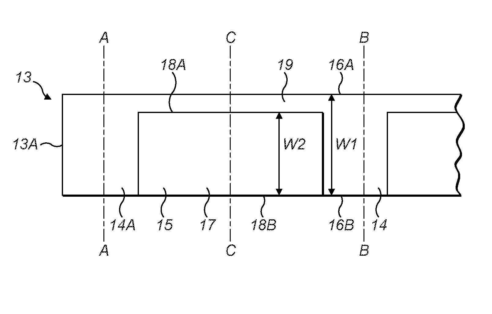
[0022] FIG. 3 is a top view of part of a composite web for forming the smoking article element wrapper of FIG. 2;
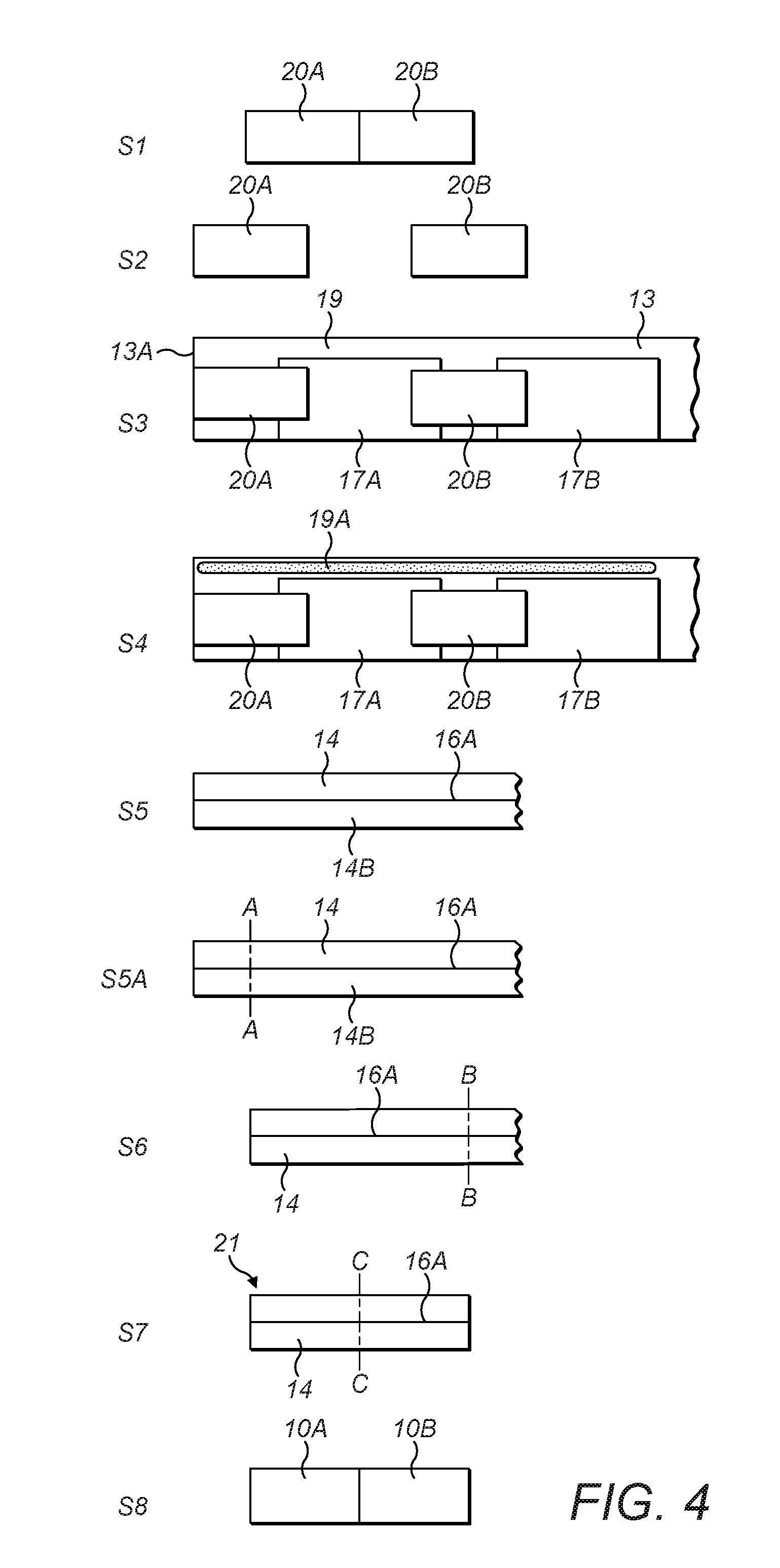
[0023] FIG. 4 shows a schematic representation of steps in a method of manufacturing a smoking article component of the smoking article of FIG. 1;
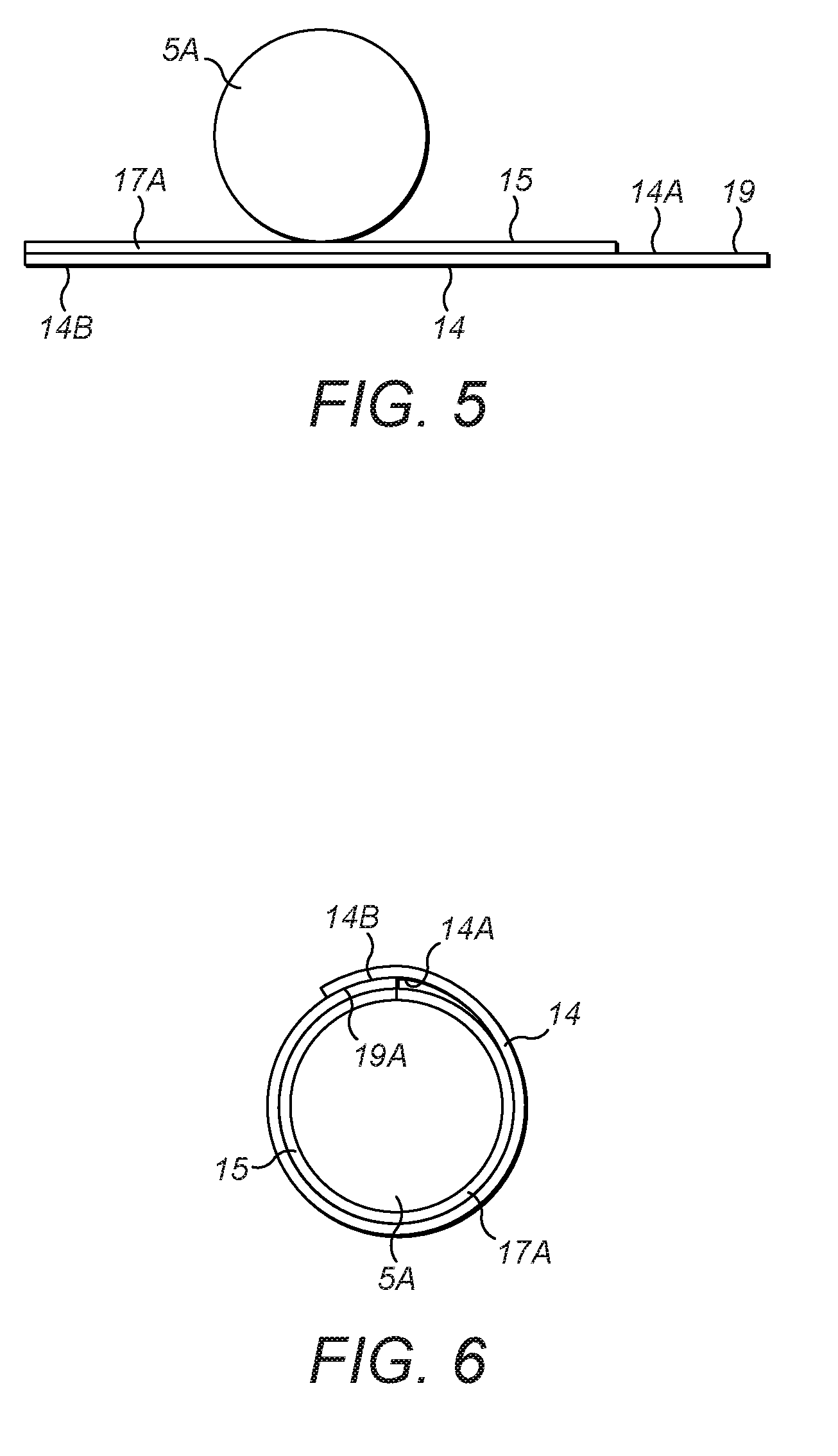
[0024] FIG. 5 is an end view of a partially assembled smoking article component of the smoking article of FIG. 1, after a third step in the manufacturing method of FIG. 4;
[0025] FIG. 6 is an end view of a partially assembled smoking article component of the smoking article of FIG. 1, after an fifth step in the manufacturing method of FIG. 4;
[0026] FIG. 7 is a cross-sectional side view of a partially assembled smoking article component of the smoking article of FIG. 1, after a sixth step in the manufacturing method of FIG. 4;
[0027] FIG. 8 is a perspective view of a partially assembled smoking article component of the smoking article of FIG. 1, after an eighth step in the manufacturing method of FIG. 4;
[0028] FIG. 9 is a perspective view of a smoking article component of the smoking article of FIG. 1; and,
[0029] FIG. 10 is a schematic side view of an apparatus for use in the manufacturing method of FIG. 4.
DETAILED DESCRIPTION
[0030] A portion of a smoking article 1 according to an embodiment of the invention is shown in FIG. 1. The smoking article 1 comprises a tobacco rod 2 and a smoking article component 3. An outer wrap 4 circumscribes the tobacco rod 2 and the smoking article component 3.
[0031] The smoking article component 3 is arranged co-axially with the tobacco rod 2 such that the smoking article 1 is generally cylindrical. The smoking article component 3 comprises a smoking article element 5 and a smoking article element wrapper to that is wrapped around the smoking article element 5.
[0032] The wrapper to extends past an end of the smoking article element 5 to define a recess 6. The recess 6 is filled with a medium 7. The medium 7 may comprise, for example, a flavourant, substrate of tobacco and/or filtration medium in the form of a granular material or gel. The wrapper to circumscribes the recess 6 and abuts an inner surface of the outer wrap 4.
[0033] The wrapper to is shown in more detail in FIG. 2, in a flat state prior to being wrapped around the smoking article element 5.
[0034] The wrapper to comprises an inner layer 11 and a plug wrap 12. The wrapper to is configured such that the inner layer 11 is located proximate to the smoking article element 5 and recess 6 and the plug wrap 12 is located proximate the outer wrap 4. In one embodiment, the plug wrap 12 is permeable and a portion of the smoking article element 5 is not circumscribed by the inner layer 11, which may be air impermeable, in order to allow for ventilation air to enter into the smoking article element 5 in the radial direction thereof.
[0035] The inner layer 11 of the wrapper to comprises a thermally conductive material that facilitates a more even heat distribution over the periphery of the smoking article element 5 and recess 6, since the inner layer 11 conducts heat from hotter regions of the periphery of the smoking article element 5 and recess 6 to cooler regions thereof. Therefore, the thermally conductive inner layer 11 helps to equalise the temperatures of the smoking article element 5 and recess 6.
[0036] The wrapper to is manufactured from a composite web 13, which is shown in FIG. 3. The composite web 13 comprises a strip of wrapping material 14 in the form of a paper strip 14 and a thermally conductive layer 15 in the form of aluminium foil 15. The paper strip 14 forms the plug wrap 12 of the wrapper to and the thermally conductive layer 15 forms the inner layer 11. The thermally conductive layer 15 is disposed on an inner surface 14A of the paper strip 14.
[0037] The paper strip 14 comprises parallel first and second longitudinal edges 16A, 16B and has a width W1 that extends between the first and second longitudinal edges 16A, 16B.
[0038] The thermally conductive layer 15 comprises a plurality of conductive patches 17. Each of the conductive patches 17 is substantially rectangular and comprises parallel first and second edges 18A, 18B. In the present embodiment, each of the conductive patches 17 is manufactured from aluminium foil. However, it should be recognised that in other embodiments of the invention the conductive patches 17 may be formed from a different thermally conductive material, for example a different kind of metallic foil, such as silver foil, or a metallic paper, such as aluminium or silver paper.
[0039] The plurality of conductive patches 17 are disposed on the paper strip 14 and are spaced in the longitudinal direction of the paper strip 14 to form a plurality of discrete sections of thermally conductive material. The conductive patches 17 are secured to the paper strip 14 by an adhesive. Alternatively, or additionally, the conductive patches 17 may be laminated to the paper strip 14.
[0040] The second edge 18B of each conductive patch 17 extends to and overlies the second longitudinal edge 16B of the paper strip 14. Each conductive patch 17 has a width W2 that extends between the first and second edges 18A, 18B of the conductive patch 17. In the exemplary embodiment shown, the width W2 of each conductive patch 17 is smaller than the width W1 of the paper strip 14 such that the first edge 18A of each conductive patch 17 is spaced from the adjacent first longitudinal edge 16A of the paper strip 14. Therefore, a portion of the inner surface 14A of the paper strip 14, located between the first longitudinal edge 16A of the paper strip 14 and the first edges 18A of the conductive patches 17, is not covered by the conductive patches 17 and instead forms an uncovered portion 19. The uncovered portion 19 of the paper strip 14 extends uninterrupted in the longitudinal direction of the paper strip 14.
[0041] In the present embodiment, the difference between the width W1 of the paper strip 14 and the width W2 of each conductive patch 17 is between 1 to 10 mm, and preferably between 3 to 7 mm, such that the width of the uncovered region 19 is between 1 to 10 mm, and preferably between 3 to 7 mm. In one embodiment, the width W1 of the paper strip is between 12 to 19 mm and the width W2 of each conductive patch 17 is between 11 to 17 mm. However, it should be recognised that each width W1, W2 and the difference between the widths W1, W2 may be different from that described above. In one embodiment, the width W2 of each conductive patch 17 is larger than the circumference of the smoking article element 5 such that the conductive patch 17 subtends around the entire periphery of the smoking article element 5 and the first and second edges 18A, 18B overlap around the smoking article element 5. In an alternative embodiment, the width W2 of each conductive patch 17 is substantially the same as the circumference of the smoking article element 5 such that the conductive patch 17 subtends around the entire periphery of the smoking article element 5 and the first and second edges 18A, 18B abut, as shown in FIG. 6 described in more detail below. It should be noted that the paper strip 14 sits flush against, and remains adhered to, the first conductive patch 17A about the circumference of the first and second smoking article elements 5A, 5B and is not detached therefrom proximate the area of overlap/abutment, as shown in FIG. 6.
[0042] In an alternative embodiment (not shown), the width W1 of the paper strip 14 is equal to the width W2 of each conductive patch 17. In such an embodiment, the first longitudinal edge 18A of each conductive patch 17 overlies the first longitudinal edge 16A of the paper strip 14 and the second longitudinal edge 18B of each conductive patch 17 overlies the second longitudinal edge 16B of the paper strip 14 so that the composite web 13 does not comprise an uncovered region between the first longitudinal edges 16A, 18A.
[0043] Referring to FIG. 4, a method of manufacturing first and second smoking article components 3A, 3B according to an embodiment of the invention is shown.
[0044] At step S1, a continuous cylindrical portion of smoking article element material is cut to form double-length first and second rods 20A, 20B. At step S2, the first and second rods 20A, 20B are positioned such that they are axially spaced from each other.
[0045] At step S3, the first rod 20A is positioned on the composite web 13 (as shown in FIG. 5) such that is located at a free end 13A of the composite web 13 with an end overlapping a first conductive patch 17A. Also at step S3, the second rod 20B is positioned such that an end overlaps the first conductive patch 17A and an opposite end overlaps a second conductive patch 17B that is adjacent, but spaced from, the first conductive patch 17A. The first and second rods 20A, 20B are axially spaced on the composite web 13. Step S2 may be omitted and the first and second rods 20A, 20B may be supplied sequentially spaced on the continuous composite web 13.
[0046] At step S4, adhesive is applied along one edge of the composite web 13, specifically in the exemplary embodiment shown, along the region of the uncovered portion 19 of the paper strip 14 that is proximate to the free end 13A of the composite web 13 to form an adhesion region 19A.
[0047] At step S5, the composite web 13 is wrapped around the first and second rods 20A, 20B such that the adhesion region 19A overlaps a portion of the outer surface 14B of the paper strip 14 and is adhered thereto by the adhesive (as shown in FIG. 6). An advantage of the arrangement of the exemplary embodiment shown in that, since the adhesion region 19A comprises part of the uncovered portion 19 of the inner surface 14A of the paper strip 14, which is formed from the same material as the outer surface 14B of the paper strip 14, it is easier to adhere the uncovered portion 19 to the outer surface 14B of the paper strip 14 and the bond is stronger and/or a weaker adhesive or less adhesive may be used than if they were made from dissimilar materials. For example, if the paper strip 14 instead did not comprise an uncovered portion 19, then the aluminium foil of the first and second conductive patches 17A, 17B would need to be adhered to the paper outer surface 14B of the paper strip 14 and so the adhesive would provide a weaker bond. Therefore, the resultant smoking article 1 would not be as robust, although an increased amount of adhesive and/or a stronger adhesive may be used to mitigate this.
[0048] The width W2 of the first and second conductive patches 17A, 17B may be the same as the circumference of the first and second rods 20A, 20B such that the first and second conductive patches 17A, 17B extend around the entire circumference of the respective first and second rods 20A, 20B so that the first and second edges 18A, 18B, thereof abut, as shown in FIG. 6. In another embodiment, the width W2 of the first and second patches 17A, 17B is greater than the circumference of the first and second rods 20A, 20B such that the first and second edges 18A, 18B of each of the first and second conductive patches 17A, 17B overlap.
[0049] At step S5A, the composite web 13 and first rod 20A are cut along a first cut-line (shown by the chain-dashed line `A-A` in FIG. 3). The first cut-line A-A extends perpendicularly to the longitudinal direction of the paper strip 14 and is located at the centre of the first rod 20A, parallel to the free end 13A of the composite web 13. When the composite web 13 and first rod 20A are cut along the first cut-line A-A, one half the first rod 20A and a section of the composite web 13 at the free end 13A are separated from the remainder of the composite web 13.
[0050] At step S6, the composite web 13 is cut along a second cut-line (shown by the chain-dashed line `B-B` in FIG. 3). The second cut-line B-B extends perpendicularly to the longitudinal direction of the paper strip 14 and is located in the middle of the second rod 20B, half-way between the first and second conductive patches 17A, 17B. When the second rod 20B is cut along the second cut-line B-B, the second rod 20B is split into a second smoking article element 5B, which is proximate to but spaced from the first smoking article element 5A, and a third smoking article element (not shown), which is distal to the first smoking article element 5A. As a result, an end portion of the composite web 13 is separated from the remainder of the continuous composite web 13 and circumscribes the first and second smoking article elements 5A, 5B to form a tubular structure 21 (as shown in FIG. 7). It should be noted that, contrary to what is shown in the schematic diagram of FIG. 7, the portion of the paper strip 14 at the distal ends of the tubular structure 21 sits flush against the first and second smoking article elements 5A, 5B and is not spaced therefrom as shown in FIG. 7.
[0051] The above-described cutting of the composite web 13 results in a tubular structure 21 known as a "2-up" rod, namely it is two smoking article elements 5A, 5B and joined together with a section of composite web 13 which can eventually be cut in half to provide two single smoking article components. However, in alternative embodiments of the invention, the second cut line B-B may be made at a rod one or more rods spacing from the first rod 20A. This would result in a tubular element 21 comprising a first smoking article element 5A and a second smoking article element 5B spaced from each other and with one or more double-length rods between them and spaced from them. Such tubular elements are known as "4-up", "6-up", "8-up" etc. rods.
[0052] At step S7, the composite web 13 of the tubular structure 21 is cut along a third cut-line (shown by the chain-dashed line `C-C` in FIG. 3) to form first and second smoking article element wrappers 10A, 10B, which circumscribe the first and second smoking article elements 5A, 5B respectively. The third cut-line C-C extends perpendicularly to the longitudinal direction of the paper strip 14 and is located in the middle of the first conductive patch 17A, equidistant to the first and second smoking article elements 5A, 5B.
[0053] A portion of the first wrapper 10A extends past the end of the first smoking article element 5A in the axial direction thereof to form a cup-shape which defines a first recess 6A (as shown in FIG. 8). Similarly, a portion of the second wrapper 10B extends past the end of the second smoking article element 5B to form a cup-shape which defines a second recess 6B (as shown in FIG. 8).
[0054] The first and second smoking article elements 5A, 5B are axially spaced from each other and this space therebetween forms the first and second recesses 6A, 6B when the tubular structure 21 is cut along the third cut line C-C. This arrangement provides the advantage that the end portion of the composite web 13 is supported at each end by the first and second smoking article elements 5A, 5B as the tubular structure 21 is cut along line C-C and so helps to prevent the composite web 13 from creasing or crumpling.
[0055] At step S8, the first and second wrappers 10A, 10B are separate elements and subsequently, the first and second wrappers 10A, 10B with respective enveloped smoking article elements 5A, 5B, are moved apart from each other and the first and second recesses 6A, 6B are filled with a medium 7A, 7B, for example granules of flavourant or filtration material, to form first and second smoking article components 3A, 3B (as shown in FIG. 9). Each of the smoking article components 3A, 3B comprises a smoking article element 5A, 5B, smoking article element wrapper 10A, 10B and medium 7A, 7B. The smoking article components 3A, 3B are then attached to respective tobacco rods to form smoking articles using a tipping wrapper in a known manner.
[0056] In one embodiment, the first and second smoking article elements 5A, 5B and the first and second wrappers 10A, 10B, which are secured thereto, are orientated such that the first and second recesses 6A, 6B face upwardly prior to being filled with the medium 7A, 7B. That is, a subsequent manufacturing step comprises orienting the components from a substantially horizontal position to a substantially vertical position prior to filling the recesses 6A, 6B with medium 7A, 7B.
[0057] Steps of the method can then be repeated to manufacture further smoking article components as a continuous process. For example, in one embodiment a double-length third rod of smoking article element material (not shown) is positioned on the remaining composite web 13 such that an end overlaps the second conductive patch 17B and an opposite end overlaps a third conductive patch that is adjacent, but spaced from, the second conductive patch 17B. Adhesive is then applied to the region of the uncovered portion 19 of the paper strip 14 and the composite web 13 is wrapped around the third rod and the third smoking article element (not shown), which is located at the end of the composite web 13 and is formed from the second rod 20B. The composite web 13 and third rod are then cut such that the third rod is split in half into a fourth smoking article element (not shown), which is spaced from the third smoking article element, and a fifth smoking article element (not shown), which is on the other side of the fourth smoking article element to the third smoking article element. Thus, a portion of the composite web 13 circumscribes the third and fourth smoking article elements and forms a tubular structure (not shown). The tubular structure is then cut across its central axis to form third and fourth smoking article element wrappers (not shown), which circumscribe and extend past the third and fourth smoking article elements respectively to form corresponding recesses. The recesses may then be filled with a medium to form third and fourth smoking article components (not shown).
[0058] In the above described embodiment, each of steps S1 to S8 are performed sequentially. However, it should be recognised that one or more of steps S1 to S8 may be performed simultaneously. Furthermore, it should be recognised that steps S1 to S8 may be performed in a different order to that shown in FIG. 4.
[0059] In one alternative embodiment, steps S1 to S6 are performed in one process and steps S7 and S8, including subsequent filling with medium 7A, 7B and securing to tobacco rods 2 to form a smoking article, are performed in a second, separate process. That is, multiple tubular structures 21 are manufactured in one process and the plurality of tubular structures 21 are then stored and transported to a separate apparatus that performs steps S7 to S8 and subsequent formation of a plurality of smoking article components and subsequent combination with tobacco rods 2 to form smoking articles. Such pre-forming of the tubular structures 21 allows for the tubular structures 21 to be easily stored and then used with different processes depending on the medium that is to be used to fill the recesses of the smoking article components.
[0060] An apparatus 30 for performing steps of the manufacturing method of FIG. 4 is shown schematically in FIG. 10. The apparatus 30 comprises a spacing station 31, wrapping station 32 and a cutting station 33.
[0061] The spacing station 31 comprises a first conveyor belt 35 and a first cutting blade 36. The wrapping and cutting stations 32, 33 together comprise a second conveyor belt 37. The first conveyor belt 35 comprises distal first and second ends 35A, 35B and the second conveyor belt 37 comprises distal first and second ends 37A, 37B.
[0062] The first conveyor belt 35 is advanced at a constant speed and the second conveyor belt 37 is advanced at a constant speed. The first and second conveyor belts 35, 37 move objects placed thereon in a conveyance direction (shown by arrow `X` in FIG. 10). The first and second conveyor belts 35, 37 are arranged such that objects positioned on the first conveyor belt 35 are advanced from the first end 35A to the second end 35B thereof and then pass onto the first end 37A of the second conveyor belt 37. The objects advanced onto the second conveyor belt 37 then pass from the first end 37A to the second end 37B thereof.
[0063] A continuous cylindrical portion of smoking article element material is disposed on the first end 35A of the first conveyor belt 35, and the first cutting blade 36 cuts the cylindrical portion of smoking article element material into discrete double-length first and second rods 20A, 20B. The first and second rods 20A, 20B are axially aligned on the first conveyor belt 35. The movement of the first conveyor belt 35 advances the first and second rods 20A, 20B in the conveyance direction X and onto the first end 37A of the second conveyor belt 37.
[0064] The constant speed of the second conveyor belt 37 is greater than constant speed of the first conveyor belt 35. Therefore, when the first and second rods 20A, 20B are advanced onto the second conveyor belt 37 they are accelerated from the speed of the first conveyor belt 35 to the speed of the second conveyor belt 37. The first rod 20A is positioned in front of the second rod 20B in the conveyance direction X and so advances onto the second conveyor belt 37 before the second rod 20B. Therefore, the first rod 20A will be accelerated to the speed of the second conveyor belt 37 before the second rod 20B such that the first and second rods 20A, 20B are axially spaced in the conveyance direction X on the second conveyor belt 37.
[0065] The first and second rods 20A, 20B are then advanced to the wrapping station 32. The wrapping station 32 comprises a reel 38 of composite web 13 of the type shown in FIG. 3, a tongue 39 and an adhesive applicator 40. The composite web 13 is fed from the reel 38 onto the second conveyor belt 37 such that it is advanced along the second conveyor belt 37 in the conveyance direction X.
[0066] The tongue 39 is a tapered duct having a wide entrance opening 39A and a narrow exit opening 39B. The tongue 39 is generally circular in cross-section and may be open at its underside in the form of an elongate slot (not shown) extending along the length of the tongue 39 in an axial direction thereof such that, in cross-section, the tongue 39 does not quite form a complete circle. The tongue 39 may be located on a guide (not shown) which comprises a shaped track along which the second conveyor belt 37 advances.
[0067] The composite web 13 is fed from the reel 38 onto the surface of the second conveyor belt 37. The adhesive applicator 40 is configured to apply adhesive along an edge of the paper strip, and in the embodiment shown, along the uncovered portion 19 of the paper strip 14, proximate the free end 13A of the composite wrap 13, to form an adhesion region 19A.
[0068] The advance of the first and second rods 20A, 20B onto the second conveyor belt 37 is timed with the advance on the composite web 13 on the second conveyor belt 37 such that the first rod 20A is located with an end overlapping a first conductive patch 17A. The second rod 20B is located such that an end overlaps the first conductive patch 17A and an opposite end overlaps a second conductive patch 17B that is adjacent to, but spaced from, the first conductive patch 17A.
[0069] The composite web 13 is conveyed through the tongue 39 in the conveyance direction X by the movement of the second conveyor belt 37. As the composite web 13 travels though the tongue 39, the shaped track of the tongue 39 is configured to deform the second conveyor belt 37 and the portion of the composite web 13 thereon such that, in cross-section, the composite web 13 goes from being flat (as it is on the reel 38) when it enters the wide entrance opening 39A of the tongue 39, to a closed circle as it leaves the narrow exit opening 39B of the tongue 39, circumscribing the first and second rods 20A, 20B. The composite web 13 is orientated such that when the composite web 13 passes through the tongue 39 the first and second conductive patches 17A, 17B face inwardly towards the first and second rods 20A, 20B respectively and the paper strip 14 forms the outer circumference of the wrapped composite web 13.
[0070] The tongue 39 is shaped such that the adhesion region 19A contacts the outer surface 14B of the paper strip 14 when the composite web 13 is wrapped around the first and second rods 20A, 20B. This causes the adhesion region 19A to be adhered to said outer surface 14B of the paper strip 14 such that the composite web 13 is fixed in a cylindrical shape. Thus, the composite web 13 is wrapped around the outside of the first and second rods 20A, 20B such that when the first and second rods 20A, 20B exit though the narrow exit opening 39B of the tongue 39 they are surrounded by the composite web 13.
[0071] The composite web 13 and the first and second rods 20A, 20B are then advanced in the conveyance direction X to the cutting station 33. The cutting station 33 comprises a second cutting blade 41, and may optionally include a third cutting blade 42.
[0072] The second cutting blade 41 is configured to cut the composite web 13 and the first rod 20A along the first cut-line A-A as they exit the tongue 39. When the composite web 13 and first rod 20A are cut along the first cut-line A-A, one half the first rod 20A and the portion of the composite web 13 at the free end 13A are separated from the remainder of the composite web 13. The other half of the first rod 20A forms a first smoking article element 5A.
[0073] The second cutting blade 41 is configured to then cut the composite web 13 and second rod 20B along the second cut line B-B as they exit the tongue 39 such that the second rod 20B is separated into a second smoking article element 5B and a third smoking article element (not shown). An end portion of the composite web 13 is separated from the remainder of the composite web 13 and circumscribes the first and second smoking article elements 5A, 5B, which are axially spaced, to form a tubular structure 21. This comprises a "2-up" rod of effectively two smoking article components 3A, 3B joined together and without medium 7A, 7B. The above process continues as a continuous process to form multiple tubular structures 21.
[0074] In an optional configuration of the apparatus 3o, a third cutting blade 42 may then cut the portion of the composite web 13 that is part of the tubular structure 21 along the third cut-line C-C to form first and second smoking article element wrappers 10A, 10B. The first and second wrappers 10A, 10B circumscribe the first and second smoking article elements 5A, 5B respectively. However, the third cutting blade 42 may be omitted and the "2-up" rod may then be discharged at the end of the apparatus 30 to be collected, stored and transported to a separate smoking article manufacturing apparatus to be formed into smoking articles with medium 7A, 7B in the recesses 6A, 6B.
[0075] Whether cut with the third cutting blade 42 or cut as part of a subsequent smoking article manufacturing process, in the resulting tubular structures 21 once cut, a portion of the first wrapper 10A extends past the end of the first smoking article element 5A in the axial direction thereof to form a cup-shape which defines a first recess 6A. Similarly, a portion of the second wrapper 10B extends past the end of the second smoking article element 5B to form a cup-shape which defines a second recess 6B.
[0076] The first and second recesses 6A, 6B are then filled with a medium 7A, 7B to form first and second smoking article components 3A, 3B. The first and second smoking article components 3A, 3B are each attached to a tobacco rod to form respective smoking articles.
[0077] The composite web 13 may be manufactured by adhering the conductive patches 17A, 17B to the paper strip 14 and then rolling the composite web 13 into a reel. This causes the thermally conductive patches 17A, 17B to be compressed against the paper strip 14 to promote adhesion thereto.
[0078] In the above described embodiment, the first and second rods 20A, 20B are axially spaced on the composite web 13 by advancing each of the first and second rods 20A, 20B onto a second conveyor belt 37 that accelerates each of the first and second rods 20A, 20B. However, it should be recognised that other means of axially spacing the first and second rods 20A, 20B are intended to fall within the scope of the invention. For example, the first and second rods 20A, 20B could instead be axially spaced by hand, by compressed air, or by locating both of the first and second rods 20A, 20B in groove on a rotating spacing drum and then urging an element between the first and second rods 20A, 20B such that they become axially spaced in the groove of the rotating spacing drum. Furthermore, the steps in the above-described method of the invention of providing a tubular structure 21, be it a 2-up, 4-up, 6-up etc. rod, and cutting as appropriate, separating, aligning, and subsequent smoking article manufacturing steps, may be achieved using a system of a plurality of drums, as is known in the art.
[0079] In the above described embodiment, the composite web 13 is cut by the second cutting blade 41 such that the tubular structure 21 comprises first and second smoking article elements 5A, 5B. However, in an alternate embodiment (not shown) the tubular structure instead comprises a different number of smoking article elements, for example four, six or eight smoking article elements known as "4-up", "6-up", or "8-up" tubular structures. In such tubular structures, the distal ends comprise single smoking article elements and between these and spaced from each and each other are one or more double length rods 20A, 20B, i.e. one double length rod in a 4-up tubular structure, two double length rods in a 6-up tubular structure, three double length rods in a 8-up tubular structure, etc. In one alternative embodiment, a third rod of smoking article element material is located on the composite web, axially spaced from the second rod on the other side thereof to the first rod. The composite wrapper is wrapped around the first, second and third rods and is then cut such that the third rod is split in half axially to form a 4-up tubular structure. The tubular structure comprises the second (double length) rod in the middle of the tubular structure with a (single length) smoking article element at each end, axially spaced from the second rod. The 4-up tubular structure can then be cut three times such that the tubular structure is split into four smoking article components, each comprising a smoking article element and a recess.
[0080] In the above described embodiment, double-length rods 20A, 20B are provided on the composite web 13 and are then cut in half to form smoking article elements 5, 5A, 5B. However, in an alternate embodiment (not shown), smoking article elements that have been pre-cut to size may be provided on the composite web.
[0081] In the above described embodiment, the first and second rods 20A, 20B are positioned axially spaced on a continuous length of composite web 13 which is then wrapped around the first and second rods 20A, 20B. The composite web 13 and first and second rods 20A, 20B are then cut to form the tubular structure 21. However, in an alternate embodiment (not shown) the composite web is first cut to size and then the first and second smoking article elements are positioned thereon, axially spaced from each other. The composite web is then wrapped around the first and second smoking article elements to form the tubular structure, which is subsequently cut in half to form first and second wrappers circumscribing the first and second smoking article elements respectively. In one embodiment, the composite web is wrapped around the smoking article element using a rolling drum configuration of the type known in the art. An advantage of this alternative arrangement is that the first and second smoking article elements support the composite web at each end thereof which may help to prevent the composite web 13 from creasing or crumpling during wrapping. For example, if the smoking article elements were not axially spaced and instead were located proximate to each other in the middle of the portion of the composite web 13, then the ends of the composite web 13 would not be supported by the first or second smoking article elements 5A, 5B. Therefore, the free ends of the composite web 13 could crease or crumple when the composite web 13 is wrapped around the smoking article elements 5A, 5B.
[0082] In one embodiment, the or each smoking article element 5, 5A, 5B is in the form of a filter element (not shown), for example comprising a plug of filtration material. In an alternate embodiment, the or each smoking article element 5, 5A, 5B is in a different form.
[0083] Although in the above described embodiments the strip of wrapping material 14 is in the form of a paper strip 14, in alternate embodiments (not shown) the strip of wrapping material 14 may comprise a different material, for example plastic wrap. The strip of wrapping material 14 may be permeable to allow for the flow of air into the smoking article element 5, 5A, 5B in the axial direction thereof.
[0084] As used herein, the term "smoking article" includes smokeable products such as cigarettes, cigars and cigarillos whether based on tobacco, tobacco derivatives, expanded tobacco, reconstituted tobacco or tobacco substitutes and also heat-not-burn products, tobacco heating devices, and other nicotine delivery product such as aerosol generation devices including e-cigarettes. The smoking article may be provided with a filter for the gaseous flow drawn by the smoker.
[0085] In order to address various issues and advance the art, the entirety of this disclosure shows by way of illustration various embodiments in which the claimed invention(s) may be practiced and provide for a superior composite web and method of manufacturing a smoking article element component. The advantages and features of the disclosure are of a representative sample of embodiments only, and are not exhaustive and/or exclusive. They are presented only to assist in understanding and teach the claimed features. It is to be understood that advantages, embodiments, examples, functions, features, structures, and/or other aspects of the disclosure are not to be considered limitations on the disclosure as defined by the claims or limitations on equivalents to the claims, and that other embodiments may be utilised and modifications may be made without departing from the scope and/or spirit of the disclosure. Various embodiments may suitably comprise, consist of, or consist essentially of, various combinations of the disclosed elements, components, features, parts, steps, means, etc. In addition, the disclosure includes other inventions not presently claimed, but which may be claimed in future.
* * * * *
D00000
D00001
D00002
D00003
D00004
D00005
XML
uspto.report is an independent third-party trademark research tool that is not affiliated, endorsed, or sponsored by the United States Patent and Trademark Office (USPTO) or any other governmental organization. The information provided by uspto.report is based on publicly available data at the time of writing and is intended for informational purposes only.
While we strive to provide accurate and up-to-date information, we do not guarantee the accuracy, completeness, reliability, or suitability of the information displayed on this site. The use of this site is at your own risk. Any reliance you place on such information is therefore strictly at your own risk.
All official trademark data, including owner information, should be verified by visiting the official USPTO website at www.uspto.gov. This site is not intended to replace professional legal advice and should not be used as a substitute for consulting with a legal professional who is knowledgeable about trademark law.