Spray Device With Flow Measurement
GUTSMANN; Volker
U.S. patent application number 16/107329 was filed with the patent office on 2019-01-03 for spray device with flow measurement. This patent application is currently assigned to Bayer CropScience Aktiengesellschaft. The applicant listed for this patent is Bayer CropScience Aktiengesellschaft. Invention is credited to Volker GUTSMANN.
| Application Number | 20190000065 16/107329 |
| Document ID | / |
| Family ID | 60951672 |
| Filed Date | 2019-01-03 |
| United States Patent Application | 20190000065 |
| Kind Code | A1 |
| GUTSMANN; Volker | January 3, 2019 |
SPRAY DEVICE WITH FLOW MEASUREMENT
Abstract
The invention relates to the application of liquid active substances with the aid of a portable spray device. The subject matter of the present invention is a portable device for applying active substances, and a method for applying active substances with the aid of a portable spray device.
| Inventors: | GUTSMANN; Volker; (Langenfeld, DE) | ||||||||||
| Applicant: |
|
||||||||||
|---|---|---|---|---|---|---|---|---|---|---|---|
| Assignee: | Bayer CropScience
Aktiengesellschaft Monheim am Rhein DE |
||||||||||
| Family ID: | 60951672 | ||||||||||
| Appl. No.: | 16/107329 | ||||||||||
| Filed: | August 21, 2018 |
Related U.S. Patent Documents
| Application Number | Filing Date | Patent Number | ||
|---|---|---|---|---|
| PCT/EP2017/066608 | Jul 4, 2017 | |||
| 16107329 | ||||
| 62360548 | Jul 11, 2016 | |||
| 62360555 | Jul 11, 2016 | |||
| Current U.S. Class: | 1/1 |
| Current CPC Class: | B05B 9/08 20130101; B05B 12/006 20130101; A01M 7/0017 20130101; B05B 12/08 20130101; B05B 12/1436 20130101; B05B 7/32 20130101; A01M 21/043 20130101; B05B 9/0861 20130101; A01M 25/006 20130101; A01M 7/0092 20130101; B05B 12/124 20130101; B05B 11/0054 20130101; A01M 7/0046 20130101 |
| International Class: | A01M 7/00 20060101 A01M007/00; B05B 9/08 20060101 B05B009/08 |
Foreign Application Data
| Date | Code | Application Number |
|---|---|---|
| Jul 11, 2016 | EP | 16178764.3 |
| Jul 11, 2016 | EP | 16178766.8 |
Claims
1. A portable spray device that can be carried by a user comprising: a first container for containing a first liquid, a connector configured to removably connect to a second container containing a second liquid, a spray nozzle in fluid communication with the first container and configured to be in fluid communication with the second container, a flow meter for measuring the flow of the first liquid from the first container in a direction of the spray nozzle, a mixing chamber comprising an inlet for the first liquid, an inlet for the second liquid, and an outlet for a mixture of the first liquid and the second liquid, and a controller unit configured to adjust a flow of the second liquid in the direction of the spray nozzle based on the measured flow of the first liquid.
2. The spray device of claim 1, wherein the first container comprises a pressure tank configured to be pressurized.
3. The spray device of claim 1, wherein the first container comprises a flexible bag configured to be unpressurized.
4. The spray device of claim 1, wherein the spray device is a backpack device.
5. The spray device of claim 1, wherein the spray nozzle is replaceable.
6. The spray device of claim 1, comprising a pressure sensor configured to measure a pressure in a supply line to the spray nozzle.
7. The spray device of claim 6, wherein the pressure sensor is connected to the control unit and the control unit is configured to keep the pressure in front of the spray nozzle within a predefined range during use of the spray device.
8. The spray device of claim 1, wherein the second liquid is an active substance concentrate, and the first liquid is a diluent.
9. The spray device of claim 8, wherein the first liquid is water.
10. The spray device of claim 8, wherein the second liquid comprises a pesticide, an insecticide, a herbicide or a fungicide.
11. The spray unit of claim 1, wherein the controller unit is configured to adjust a mixing ratio for the first liquid and the second liquid based on information stored on a second container connected to the connector.
12. The spray unit of claim 1, wherein the flow meter comprises an impeller sensor.
13. The spray device of claim 1, wherein the portable spray device comprises a screen with a mesh size in the range of 10 .mu.m to 500 .mu.m.
14. The spray device of claim 1, wherein a volume through which the second liquid flows on a way from the second container to the mixing chamber when the spray device is operated is less than 50 ml.
15. The spray device of claim 1, wherein the mixing chamber is configured to introduce the second liquid to the first liquid at an angle in the range of 20.degree. to 160.degree., when the spray device is operated.
16. The spray device of claim 1, wherein the control unit is configured to adjust a flow of the second liquid based on the measured flow of the first liquid such that the first liquid and the second liquid exit the spray device through the spray nozzle together as a mixture with a constant mixing ratio.
17. The spray device of claim 1, comprising an electrically operated pump for conveying the second liquid.
18. A backpack spray device that can be carried by a user comprising: a first container for containing a diluent, a connector configured to removably connect to a second container containing an active concentrate liquid, a spray nozzle in fluid communication with the first container and the second container, a flow meter for measuring the flow of the diluent from the first container in a direction of the spray nozzle, a mixing chamber comprising an inlet for the diluent, an inlet for the active concentrate liquid, and an outlet for a mixture of the diluent and the active concentrate liquid, and a controller unit configured to adjust a flow of the active concentrate liquid in the direction of the spray nozzle based on the measured flow of the diluent.
19. The backpack spray device of claim 18, wherein the first container comprises a pressure tank configured to be pressurized.
20. The backpack spray device of claim 18, wherein the first container comprises a flexible bag configured to be unpressurized.
21. The backpack spray device of claim 18, wherein the spray nozzle is replaceable.
22. The backpack spray device of claim 18, comprising a pressure sensor configured to measure a pressure in a supply line to the spray nozzle.
23. The spray device of claim 22, wherein the pressure sensor is connected to the control unit and the control unit is configured to keep the pressure in front of the spray nozzle within a predefined range during use of the spray device.
24. The backpack spray device of claim 18, wherein the diluent is water.
25. The spray unit of claim 18, wherein the controller unit is configured to adjust a mixing ratio for the diluent and the active concentrate liquid based on information stored on a second container connected to the connector.
26. The backpack spray device of claim 18, wherein the backpack spray device comprises a screen with a mesh size in the range of 10 .mu.m to 500 .mu.m.
27. The backpack spray device of claim 18, wherein a volume through which the active concentrate liquid flows on a way from the second container to the mixing chamber when the spray device is operated is less than 50 ml.
28. The backpack spray device of claim 18, wherein the mixing chamber is configured to introduce the active concentrate liquid to the diluent at an angle in the range of 20.degree. to 160.degree., when the spray device is operated.
29. The backpack spray device of claim 18, wherein the control unit is configured to adjust a flow of the active concentrate liquid based on the measured flow of the diluent such that the diluent and the active concentrate liquid exit the spray device through the spray nozzle together as a mixture with a constant mixing ratio.
30. A method for applying a mixture of a first liquid and a second liquid using a portable spray device that can be carried by a user comprising: filling a first container of the portable spray device with a first liquid, removably connecting a second container containing a second liquid to the portable spray device, and spraying a mixture of the first liquid and the second liquid through a spray nozzle of the spray device, wherein the spray device measures the flow of the first liquid in a direction of the spray nozzle, mixes the first liquid and the second liquid prior to the spraying of the mixture of the first liquid and the second liquid through the spray nozzle, and wherein the spray device adjusts a flow of the second liquid in the direction of the spray nozzle based on the measured flow of the first liquid.
Description
[0001] The present invention relates to the application of liquid active substances with the aid of a portable spray device. The subject matter of the present invention is a portable device for applying active substances, and a method for applying active substances with the aid of a portable spray device.
[0002] Portable spray devices for applying active substances such as pesticides, insecticides, herbicides and fungicides are known (DE102013109785A1, US2006/0249223A1, US2006/0102245 A1, US2006/0261181A1, US2005/0006400A1).
[0003] Commonly used are spray devices, which are referred to as compression sprayers. They comprise a tank for receiving the liquid to be sprayed. A generally manually operated air pressure pump which forms part of the tank contains a conventional piston rod assembly and an actuating handle for the same. This air pressure pump is used to generate an air pressure over the liquid to be sprayed. The pressurization of the tank is effected by the operator periodically actuating the pump until a desired tank pressure is reached. The spray liquid exits through a tube immersed in the liquid in the tank due to the air pressure exerted thereon and then flows through a tube, a spray jet valve at the outer end of the tube, an extension pipe and finally through a spray nozzle to the selected target area.
[0004] A disadvantage of such a spray device is that the ejection pressure can not be kept constant by the manually operated air pump. The result is a spray pattern that is changing according to the flow rate. Accordingly, the active substance can only be dosed inaccurately.
[0005] An electrically operated air pump can remedy this, but for a targeted, accurate and uniform application of the active substance, it is necessary that the pressure in the tank is kept constant. In addition, the tank must be pressure stable. In most cases such tanks are therefore made of metal or thick-walled plastic.
[0006] Pesticides, insecticides, herbicides and fungicides are nowadays increasingly brought to market in the form of concentrates. Concentrates have the advantage of lower transport costs. The user must dilute the active substance before use. The instructions for dilution are usually found on the package or on a package insert.
[0007] However, a dilution made by the user is disadvantageous for the following reasons: The user may come into undesirable contact with the active substance. It is conceivable that the user may make mistakes in calculating the amounts of concentrate and diluent. High viscosity of the concentrate may result in an inaccurate volumetric measurement of the required amount.
[0008] An inaccurate dosing of active substances can have a number of unwanted consequences. The treatment of the sprayed object can be ineffective or it can lead to an overdose. It is conceivable that regulatory requirements on quantities delivered are not met. It is conceivable that inventory control errors may occur because the quantities dispensed have been calculated incorrectly.
[0009] Another disadvantage of the spray device described above is that the tank must first be cleaned when using another active substance. If necessary, the cleaning liquid must be disposed of.
[0010] Based on the described prior art, the object was to provide a portable device for applying active substances, which is easy to handle, in which no manual dilution of concentrates is required, which delivers a precisely definable amount of active substance, and in which no time-consuming cleaning is required.
[0011] According to the invention this object is achieved by the subject of independent claims 1 and 10. Preferred embodiments can be found in the dependent claims as well as in the description.
[0012] A first subject of the present invention is thus a spray device for pest control, which can be transported by a person without mechanical aids, comprising [0013] a first container for receiving a first liquid, [0014] means for connecting a second container with a second liquid to the spray device, [0015] a spray nozzle, [0016] means for conveying the first liquid and the second liquid from their containers in the direction of the spray nozzle, [0017] a flow meter for measuring the flow of the first liquid from the first container in the direction of the spray nozzle, [0018] a mixing chamber having an inlet for the first liquid, an inlet for the second liquid and an outlet for a mixture of first and second liquids, and [0019] a control unit configured to adjust the flow of the second liquid in the direction of the spray nozzle based on the measured flow of the first liquid.
[0020] A further subject of the present invention is a method for pest control by applying a mixture of a first and a second liquid to a target object by means of a spray device that can be transported by a person without mechanical aids, comprising a first container, a spray nozzle and a valve, the method comprising the following steps: [0021] filling the first container with the first liquid, [0022] connecting a second container with the second liquid to the spray device, [0023] directing the spray nozzle at the target object, [0024] opening the valve, and [0025] applying the mixture, wherein when opening the valve, the first liquid is conveyed from the first container in the direction of the spray nozzle, the flow of the first liquid is measured by a flow meter and the measured values are transmitted to a control unit, the control unit adjusts the flow of the second liquid from the second container in the direction of the spray nozzle, so that the first and second liquids pass through the spray nozzle in a constant mixing ratio.
[0026] According to the invention, mixing the first and the second liquids occurs automatically--a manual mixing by a user is not required. The first and second liquids are kept in separate containers and are combined just prior to application onto the target object. This will help to avoid potential user errors in making the mix, and accidental contamination of the user with the liquids.
[0027] Both liquids are conveyed in the direction of the spray nozzle. They exit the spray device through the spray nozzle together as a mixture. The mixing ratio is automatically set based on the flow of the first liquid. For this purpose, a flow meter measures the flow of the first liquid from the first container in the direction of the spray nozzle and transmits the measured values to the control unit. The control unit then adjusts the flow of the second liquid in the direction of the spray nozzle on the basis of this flow of the first liquid. If, for example, the flow of the first liquid decreases, the flow of the second liquid is reduced, so that the mixing ratio remains constant. As the flow of the first liquid increases, the flow of the second liquid is increased accordingly.
[0028] The second container with the second liquid is embodied as a replaceable container, so that different liquids can be used with the spray device according to the invention. As a result, the spray device is versatile.
[0029] The individual elements which characterize the spray device according to the invention and the method according to the invention are explained in more detail below. This explanation does not distinguish between spray device and method. Instead, the following descriptions apply to all subjects of the invention analogously, irrespective of the context.
[0030] The spray device according to the invention is transportable. Transportable is understood to mean that the device can be brought from one place to another place by a person without mechanical aids.
[0031] In an embodiment, the spray device is embodied so that the user carries in transport one part of the spray device comprising the first tank in one hand, and another part of the spray device comprising the spray nozzle in the other.
[0032] Preferably, the device is embodied so that the user can carry and transport a part of the spray device, which includes the first liquid container, on the back (backpack device). Another part, which includes the spray nozzle, is still carried with one hand, but the second hand is now free. To carry the container on the back, it is equipped with appropriate straps.
[0033] The spray device is equipped with a first container for receiving a first liquid.
[0034] The term "liquid" is intended to include solutions, emulsions and suspensions.
[0035] The first liquid is preferably a diluent. The diluent is used to dilute the second liquid that is in the second container.
[0036] In a preferred embodiment, the diluent is water.
[0037] The first container preferably has an opening which can be closed with a resealable closure. The first container can be filled with the first liquid by means of this opening.
[0038] The first container may be made of any material that is compatible with the first liquid. The term "compatible" is understood to mean that the material is not chemically attacked by the first liquid and that the material is impermeable to the first liquid.
[0039] Depending on the means used to convey the first liquid from the first container in the direction of the spray nozzle, the first container must withstand an overpressure or it can be operated without pressure. In an embodiment of the present invention the first container a pressure tank, which can be pressurized to convey the first liquid by means of pressure from the first container in the direction of the spray nozzle.
[0040] In a preferred embodiment, the first container is operated without pressure. Due to the fact that the container does not have to withstand overpressure, it can be made of a more thin-walled and lighter-weight material.
[0041] In a particularly preferred embodiment, the first container is embodied as a flexible bag. Such a bag preferably has straps so that it can be strapped to and worn like a backpack on the back.
[0042] The spray device according to the invention further has means for connecting a second container with a second liquid to the spray device. As already mentioned above, the second liquid is preferably a concentrate to be diluted by the diluent. Preferably, the second liquid is an active substance formulation, preferably comprising a pesticide, insecticide, herbicide or fungicide. In a particularly preferred embodiment, it is a pesticide concentrate. Preferably, the pesticide is an agent for controlling animal pests, more preferably an acaricide (for mites/arachnids), an insecticide (for insect pests) or a rodenticide (for rodents).
[0043] According to the invention, the second liquid container is replaceable, which means that one can reversibly connect a container filled with the second liquid to the spray device. The second liquid container is then preferably removed again and, if necessary, replaced by another container when it has been emptied.
[0044] Means for reversibly connecting a container are well known. The means for connecting the container may be, for example, a screw or bayonet connection. To this end, there are mutually compatible connection means on the spray device and on the second container.
[0045] The second container is embodied to be compatible with the second liquid--i.e., it is impermeable to the second liquid and is not chemically attacked by the second liquid.
[0046] The second container may be embodied as a disposable or reusable container, i.e., it is either reusable or not suitable for reuse.
[0047] In a preferred embodiment, the second container is at least partially embodied of a plastic. Plastics are known to be chemically inert to many substances. They are also light, can be processed readily and can be formed in almost any shape.
[0048] In a preferred embodiment, the second container is embodied as a pressure vessel. Preferably, it contains a pressurized propellant separated from the second liquid, in addition to the second liquid. The second container preferably has a valve. Preferably, the valve is automatically opened when the second container is connected to the spray device according to the invention. The pressurized propellant pushes the second liquid from the second container into the spray device. Another valve located in the spray device stops the further flow of the second liquid. This additional valve preferably opens when a user starts an application operation, usually by actuating a handle.
[0049] The second container embodied as a pressure vessel may for example consist of aluminum or tin sheet--materials that are pressure resistant and, for example, are used in spray cans (e.g. shaving foam).
[0050] It is conceivable that the second container contains a bag with the second liquid, wherein the bag is connected to the valve (valve bag system). The propellant surrounds the bag filled with the second liquid and exerts the necessary pressure for expelling the second liquid from the second container (see, e.g., DE69820260T2, U.S. Pat. No. 5,505,039, EP0718213A).
[0051] It is also conceivable that the propellant and the second liquid are separated by a piston (see, e.g. DE3934237A1). The propellant exerts pressure on the piston. If the valve is opened, the second liquid is forced out of the second container by the piston. It is conceivable, for example, the use of a ZIMA piston.
[0052] In a preferred embodiment of the present invention, the second container has means that allow communication with the control unit of the spray device. In a preferred embodiment, these means allow the control unit to determine a mixing ratio. It is conceivable, for example, that the means for connecting the second container to the spray device have electrical contacts which establish an electrical contact between the spray device and the control unit when the second container is connected, by means of which electronic communication between the control unit and the second container is made possible. The second container may, for example, comprise an electronic memory which can be read by the control unit by means of the established contact. Information about the liquid present in the second container can be stored in this memory. In particular, a dilution level may be stored there, i.e. information about how the first and second liquids should be mixed.
[0053] If the second liquid is a concentrate that must be diluted with a diluent prior to application, the dilution level to be set should be noted and/or stored at or on the container. In the preferred embodiment described, the dilution level to be set is stored in a form in which it can be determined by the control unit. This can be done, as described, by means of an electronic communication. Of course, contactless communication is also possible, i.e. by means of electromagnetic waves (Bluetooth, near-field communication, etc.) in addition to the contact-based communication described.
[0054] Furthermore, the spray device according to the invention has a spray nozzle. By means of the spray nozzle, a mixture of the first and second liquids is delivered to a target object. A desired spatial distribution of the applied mixture can be achieved by means of the spray nozzle. Typically, the spray nozzle transforms the liquid passing through it into droplets having a specific droplet size distribution which depends, among other things, on the pressure of the liquid, the flow rate of the liquid and the geometry of the spray nozzle.
[0055] Preferably, the spray nozzle is replaceable, so that a user can select a spray nozzle adapted to the application and the target object with a desired drop size distribution and spatial distribution of the spray material.
[0056] The spray nozzle may, for example, be lance-shaped or pistol-shaped, or have a different shape. Preferably, it is embodied so that it can be held with one hand by the user and directed to the target object.
[0057] Typically, the spray nozzle has a handle that is actuated by the user to start a spraying operation. Usually, a valve is opened by operating the handle, so that first and second liquid are conveyed from their respective containers in the direction of the spray nozzle and through the spray nozzle to the target object.
[0058] In a preferred embodiment, the interchangeable spray nozzle and the control unit have means that allow the control unit to identify the presence of a spray nozzle and/or the type of spray nozzle present. It is conceivable, for example, that the control unit only initiates the conveyance of the liquids from their containers in the direction of the spray nozzle, only if a spray nozzle is connected also. If no spray nozzle is connected, there will be no conveyance, e.g. for safety reasons. Furthermore, it is conceivable that the control unit adapts the parameters for conveying the liquids to the type of spray nozzle present, in order to allow an optimum spray result. It is conceivable that a spray nozzle requires a minimum pressure of the incoming liquid in order to produce a desired spatial distribution of the spray liquid. This minimum pressure could be coded at the spray nozzle in a manner that can be read by the control unit so that the user does not have to manually set such parameters.
[0059] Preferably, a valve is mounted in front of the spray nozzle. Preferably, this valve can be operated manually, so that the user can direct the spray nozzle on the target object and start the spraying operation by manually opening the valve.
[0060] It is also conceivable that the valve is opened automatically. It is conceivable, for example, that the spray device has a sensor which identifies the spatial position of the spray nozzle and automatically opens or closes the valve at a certain position. It is conceivable, for example, that the valve is closed when the spray nozzle is directed to the ground and is opened when the spray nozzle is lifted in the horizontal.
[0061] It is also conceivable that the valve is opened automatically when the spray nozzle approaches the target object. This can be done for example by means of sensors or GPS-based (GPS=Global Positioning System).
[0062] The spray device according to the invention further has means for conveying the first liquid from the first container in the direction of the spray nozzle. It is conceivable that the first container can be pressurized, with which pressure the first liquid is pushed from the first container through supply lines to the spray nozzle.
[0063] Preferably, the means for conveying the first liquid from the first container in the direction of the spray nozzle comprise an electric pump. A pump has the advantage over a pressurized first container that the first container must not be constructed pressure resistant and thus is easier to transport. The first container could, in principle, even be open.
[0064] The spray device according to the invention has a flow meter for measuring the flow of the first liquid from the first container in the direction of the spray nozzle. By means of such a flow meter, the amount of liquid flowing per unit of time in the direction of the spray nozzle is detected. Amount of liquid is understood to mean the volume or the mass, depending on the measuring method used.
[0065] The flow meter is preferably one that is usually used in closed piping, such as a magnetic-inductive flow meter, a floating element flow meter, an ultrasonic flow meter, a Coriolis mass flow meter, a calorimetric flow meter or a vortex flow meter. But it is also conceivable to use a measuring orifice or a pitot tube.
[0066] In a preferred embodiment, the flow is measured with the aid of a differential pressure sensor.
[0067] In a further preferred embodiment, an impeller sensor is used for flow measurement. The measuring principle is based on the fact that an impeller assumes a speed proportional to the flow velocity of a fluid through which the impeller is driven. To measure the speed a permanent magnet can be attached to the impeller, which moves with the impeller. A Hall sensor, past which the permanent magnet passes, can be used as a pulse counter. The number of pulses measured per unit of time is proportional to the speed of the impeller and thus to the flow rate of the liquid.
[0068] Details on flow measurement can be found, for example, in the following textbook: K. W. Bonfig: Technische Durchflussmessung, Vulkan-Verlag Essen, 3rd edition, 2002, ISBN 3-8027-2190-X.
[0069] Based on the amount of liquid of the first liquid flowing in the direction of the spray nozzle, the control unit adjusts the flow of the second liquid from the second container in the direction of the spray nozzle.
[0070] The spray device according to the invention comprises means for conveying the second liquid from the second container in the direction of the spray nozzle. This is preferably an electric pump which is in communicative connection with the control unit.
[0071] In a particularly preferred embodiment, a stepper motor metering pump is used as the second pump for conveying the second liquid (see, e.g., DE102004047584, WO2012048976, DE102009006203). By means of the stepper motor drive, even small amounts of the second liquid can be added with high accuracy to the first liquid.
[0072] The first and the second liquid exit the spray device through the spray nozzle together as a mixture. It is conceivable that the first liquid and the second liquid are combined in the spray nozzle by means of corresponding supply lines. However, it has been found that the first and second liquids are not sufficiently mixed in this case when they reach the target object. Preferably, therefore, there is a mixing chamber in front of the spray nozzle, in which the first and the second liquid are introduced by means of two separate supply lines. In the mixing chamber, mixing of the first and second liquids then occurs before the mixture enters the spray nozzle.
[0073] The mixing chamber accordingly has an inlet for the first liquid, an inlet for the second liquid and an outlet for a mixture of first and second liquids. The mixing chamber may also be a portion of the supply line for the first liquid to the spray nozzle, into which a line for the second liquid opens.
[0074] The mixing of the first liquid and the second liquid can be promoted by suitable measures, for example by static mixing elements.
[0075] The lines between the second container and the mixing chamber are preferably embodied to have a small volume. After an application operation, residual amounts of the (undiluted) second liquid remain in the lines between the second container and the mixing chamber. If necessary, these residues must be disposed of; if necessary, the lines must be cleaned when changing the second container. The smaller the volume, the lower the residual quantities are that have to be disposed of and the smaller the volume to be cleaned. Preferably, the volume that the second liquid may occupy on its way in the direction of the mixing chamber between the second container and the mixing chamber is less than 50 ml, more preferably less than 30 ml, even more preferably less than 10 ml.
[0076] Preferably, the second liquid is added transversely to the flow direction of the first liquid. The term "transverse" means: at an angle in the range of 20.degree. to 160.degree., preferably 50.degree. to 130.degree., more preferably 70.degree. to 110.degree., most preferably 80.degree. to 100.degree..
[0077] In a preferred embodiment, the second liquid is dosed by a flow divider into the first liquid. In a further preferred embodiment, the second liquid is dosed into the first liquid and both liquids pass together through a flow divider. A flow divider is a static element which divides a flow of a liquid into a plurality of stream filaments. Preferably, the flow divider is embodied in the form of a screen, i.e., in the flow direction the liquid(s) is(are) forced through a screen, which divides the flow into stream filaments. By means of such a screen, in particular, drops of the second liquid which enter the first liquid are divided into a plurality of small drops. Turbulence behind the screen leads to dispersion of the small drops in the first liquid. Surprisingly, it has been found that such a screen is sufficient as a static mixing element in order to achieve sufficient mixing of first and second liquids at the spray nozzle.
[0078] If no screen is used, it can be observed that individual drops of the second liquid are retained on the route from the mixing chamber to the spray nozzle and thus an inhomogeneous mixture exits the spray nozzle. Further static mixing elements other than a screen are surprisingly not necessary to achieve sufficient mixing at the spray nozzle. In addition, a screen has the advantage of a much lower pressure loss compared to a classic static mixer, which alternately divides the fluid flow, twists it and combines it. There should be a pressure in front of the spray nozzle that is within a defined range so that the spray nozzle can achieve a desired spatial distribution of the liquid. This pressure is provided by the conveying means of the spray device. However, the pressure provided by the conveying means must be higher than the pressure required in front of the spray nozzle in order to compensate for the pressure loss across the existing supply lines, mixing chamber, mixing elements, etc. However, a higher pressure loss also means a higher energy expenditure to compensate for the pressure loss, and/or a higher pressure in the first and second containers which results in thicker container walls and, therefore, in a higher load capacity. Preferably, the screen is embodied like a mesh with a mesh size of 10 .mu.m to 500 .mu.m, more preferably 50 .mu.m to 250 .mu.m, most preferably 80 .mu.m to 120 .mu.m. The webs between the meshes usually have a width which is smaller than the mesh size in order to minimize the flow resistance and thus the pressure loss.
[0079] The spray device according to the invention has a control unit. This control unit provides for an adjustment of the amount of the second liquid from the second container in the direction of the spray nozzle. According to the invention, this adjustment is carried out on the basis of the flow of the first liquid from the first container in the direction of the spray nozzle, measured by means of the flow meter. Another parameter that is included in the adjustment is the mixing ratio to be set. This mixing ratio can be specified by the user by inputting the mixing ratio in the control unit, for example; but it is also possible that the control unit detects the mixing ratio by a communication with a memory unit of the second container.
[0080] As described above, in a preferred embodiment of the present invention, the control unit is connected to the replaceable second container such that the control unit can receive, from the replaceable second container, a dilution level to be set for the concentrate contained in the replaceable second container.
[0081] The control unit receives the measured values of the flow meter in relation to the flow of the first liquid and adjusts the flow of the second liquid so that the first and second liquids exit the spray device via the spray nozzle as a mixture with a constant mixing ratio. A "constant mixing ratio" is understood to mean that the mixing ratio over the spraying time is within a predefined range.
[0082] In a further preferred embodiment, the control unit detects the amount of second liquid applied and stores this value and transmits this value to an external computer system, for example at a user-definable time. In this way, the amount of applied second liquid can be tracked.
[0083] In a preferred embodiment, the position (which can be determined by GPS) of the application is also detected in addition to the quantity of the applied second liquid in each case.
[0084] In a further preferred embodiment, the residual quantity of second liquid in the second container is determined on the basis of the applied quantity of second liquid. Preferably, the value for this residual quantity is stored in a memory unit in the spray device and/or at the second container.
[0085] In a preferred embodiment, the spray device according to the invention has a pressure sensor which measures the pressure in the supply line to the spray nozzle.
[0086] If the first and the second liquids are conveyed in the direction of the spray nozzle, pressure builds up in front of the spray nozzle. The pressure level depends, among other things, on the geometry of the spray nozzle. It is conceivable that a spray nozzle will require a pressure that must be within a defined pressure range to generate a spray profile suitable for the application.
[0087] Therefore, the pressure sensor is preferably connected to the control unit, which adjusts the flow of the first and second liquids so that the measured pressure is in a specified range.
[0088] The invention will be explained in more detail by means of exemplary embodiments, but without wishing to limit the invention to these examples.
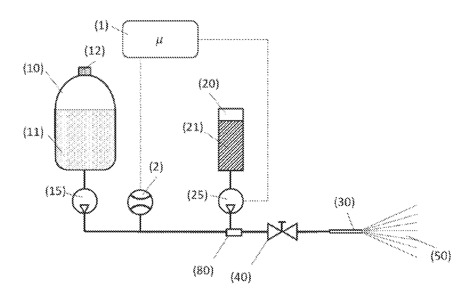
[0089] FIG. 1 shows schematically an embodiment of the spray device according to the invention. The spray device comprises a first container (10) with a first liquid (11), a second container (20) with a second liquid (21), a spray nozzle (30), a valve (40), means (15) for conveying the first liquid (11) from the first container (10) in the direction of the spray nozzle (30), means (25) for conveying the second liquid (21) from the second container (20) in the direction of the spray nozzle (30), a mixing chamber (80), a flow meter (2) for measuring the flow of the first liquid (11) from the first container (10) in the direction of spray nozzle (30), and a control unit (1).
[0090] The first container (10) is embodied as a pressure-resistant container.
[0091] In FIG. 1, the means (15) for conveying the first liquid (11) from the first container (10) are an air pump with which an overpressure in the first container (10) relative to the ambient pressure can be built up.
[0092] In FIG. 1, the means (25) for conveying the second liquid (21) from the second container (20) are an electrically operated pump.
[0093] The second liquid (21) meets the first liquid (11) in the mixing chamber (80).
[0094] When the valve (40) is opened, the first liquid (11) is conveyed by means of the conveying means (15) in the direction of the spray nozzle (30). The flow of the first liquid is measured by flow meter (2). The flow meter (2) is communicatively connected with the control unit (1) (shown by the dashed line). The flow measured by the flow meter (2) is transmitted to the control unit (1). The control unit (1) is communicatively connected with the means (25) for conveying the second liquid (21) (shown by the dashed line). The control unit (1) adjusts the flow of the second liquid (21) in the direction of the spray nozzle, so that the first liquid and the second liquid exit the spray nozzle in the form of a mixture (50) with a constant mixing ratio.
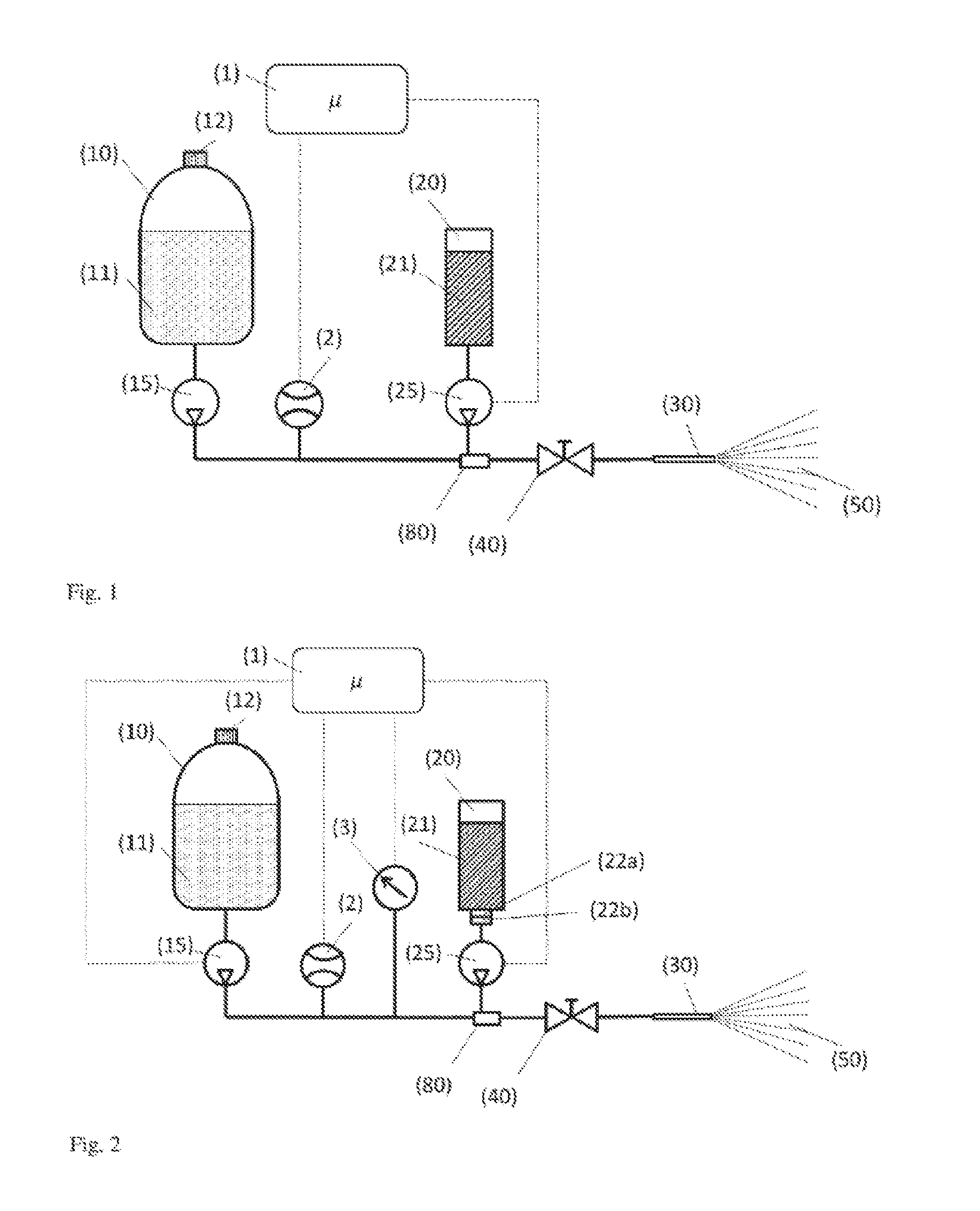
[0095] FIG. 2 shows schematically a preferred embodiment of the spray device according to the invention.
[0096] The spray device comprises a control unit (1), a flow meter (2), a pressure sensor (3), a first container (10) with a first liquid (11), a second container (20) with a second liquid (21), a first pump (15), a second pump (25), a spray nozzle (30), a mixing chamber (80) and a valve (40).
[0097] The first container (10) is embodied as a flexible bag having an opening for filling the first liquid (11), wherein the opening can be reversibly closed by a closure (12).
[0098] The second container (20) is embodied as a replaceable cartridge. The cartridge is connected by means of connecting means (22a) for connecting the cartridge to the spray device with the spray device. The spray device has connecting means (22b) compatible with the connecting means (22a) of the cartridge.
[0099] The control unit (1) is communicatively connected (shown by dashed lines) with the flow meter (2), the pressure gauge (3), the first pump (15) and the second pump (25). Preferably, the pumps (15, 25) are electrically operated.
[0100] When the valve (40) is opened, the first liquid (11) is conveyed out of the first container (10) in the direction of the spray nozzle (30) by means of the first pump (15). This flow of the first liquid (11) is measured by means of the flow meter (2). The measured value is transmitted to the control unit (1). At the same time, the pressure in the supply line to the spray nozzle (30) is measured by means of the pressure sensor (3). This measured value is also transmitted to the control unit (1). The control unit (1) adjusts the flow of the first liquid (11) and the second liquid (21) in the direction of the spray nozzle (30) by means of the first pump (15) and by means of the second pump (25) so that the exiting mixture (50) has a constant mixing ratio of first and second liquids, and so that the pressure in the supply line in front of the spray nozzle is within a predetermined range.
* * * * *
D00000
D00001
XML
uspto.report is an independent third-party trademark research tool that is not affiliated, endorsed, or sponsored by the United States Patent and Trademark Office (USPTO) or any other governmental organization. The information provided by uspto.report is based on publicly available data at the time of writing and is intended for informational purposes only.
While we strive to provide accurate and up-to-date information, we do not guarantee the accuracy, completeness, reliability, or suitability of the information displayed on this site. The use of this site is at your own risk. Any reliance you place on such information is therefore strictly at your own risk.
All official trademark data, including owner information, should be verified by visiting the official USPTO website at www.uspto.gov. This site is not intended to replace professional legal advice and should not be used as a substitute for consulting with a legal professional who is knowledgeable about trademark law.