Sealing Structure Of Plunger Pump
Li; Xiaorong ; et al.
U.S. patent application number 15/632403 was filed with the patent office on 2018-12-27 for sealing structure of plunger pump. This patent application is currently assigned to Zhejiang Rongpeng Air Tools Co., Ltd.. The applicant listed for this patent is Xiaorong Li, Fei Tang, Fazheng Yang, Xinbiao Ying. Invention is credited to Xiaorong Li, Fei Tang, Fazheng Yang, Xinbiao Ying.
| Application Number | 20180372089 15/632403 |
| Document ID | / |
| Family ID | 64692143 |
| Filed Date | 2018-12-27 |
| United States Patent Application | 20180372089 |
| Kind Code | A1 |
| Li; Xiaorong ; et al. | December 27, 2018 |
SEALING STRUCTURE OF PLUNGER PUMP
Abstract
A sealing structure of a plunger pump, comprising: a pump body and a plunger rod assembly disposed in the pump body; wherein the pump body includes an upper pump and a lower pump, and the upper pump and lower pump are fixed by screw connection; a sealing ring provided between the upper pump and the lower pump; wherein the plunger rod assembly includes an annular groove disposed at a position adjacent to a lower portion of the plunger rod at an outer peripheral surface thereof; a dynamic lip seal fitted in the annular groove; and a static lip seal sleeved on the outer peripheral surface of the plunger rod; the sealing structure of the plunger pump has good sealing effect, good anti-wear and anti-wear effect, simple replacement and low maintenance cost.
| Inventors: | Li; Xiaorong; (Taizhou, CN) ; Yang; Fazheng; (Taizhou,, CN) ; Tang; Fei; (Taizhou, CN) ; Ying; Xinbiao; (Taizhou, CN) | ||||||||||
| Applicant: |
|
||||||||||
|---|---|---|---|---|---|---|---|---|---|---|---|
| Assignee: | Zhejiang Rongpeng Air Tools Co.,
Ltd. Taizhou CN |
||||||||||
| Family ID: | 64692143 | ||||||||||
| Appl. No.: | 15/632403 | ||||||||||
| Filed: | June 26, 2017 |
| Current U.S. Class: | 1/1 |
| Current CPC Class: | F04B 53/18 20130101; F04B 53/16 20130101; F16J 15/3204 20130101; F04B 53/08 20130101; F04B 53/143 20130101; F04B 53/02 20130101 |
| International Class: | F04B 53/14 20060101 F04B053/14; F04B 53/18 20060101 F04B053/18; F04B 53/02 20060101 F04B053/02 |
Claims
1. A sealing structure of a plunger pump, comprising: a pump body and a plunger rod assembly disposed in the pump body; wherein the pump body includes an upper pump and a lower pump, and the upper pump and lower pump are fixed by screw connection; a sealing ring provided between the upper pump and the lower pump; a feed inlet disposed on the lower pump and a discharge outlet disposed on the upper pump; a lock nut disposed at an upper end of the upper pump; wherein the plunger rod assembly includes a plunger rod which extends into the pump body through a through hole in the center of the lock nut; a dust boot disposed between the plunger rod and the through hole; an annular groove disposed at a position adjacent to a lower portion of the plunger rod at an outer peripheral surface thereof; a dynamic lip seal fitted in the annular groove; and a static lip seal sleeved on the outer peripheral surface of the plunger rod; wherein the static lip seal having an upper end is disposed on a first seal ring and having a lower end is disposed on a first positioning seat; the first positioning seat is disposed on a step of an inner wall of the pump body and the first seal ring is disposed on a bottom surface of the lock nut; wherein the static lip seal and an inner wall of the upper pump have at least two gasket rings disposed therebetween; wherein the dynamic lip seal includes a second seal ring disposed at a top surface thereof and a second positioning seat disposed at a bottom surface thereof; the second seal ring and the second positioning seat are fitted in the annular groove, and are abutted against top and bottom surfaces of the annular groove, respectively; wherein the feed inlet of the lower pump includes a feeding seal ring disposed thereon; a feed valve seat disposed at the lower pump adjacent to a bottom surface of the feed inlet; a limiting seat attached to the feed valve seat; a lower pump sealing ring disposed between the feed valve seat and a bottom surface of the lower pump; and a valve ball disposed in an accommodating space which is formed between the limiting seat and the feed valve seat.
Description
BACKGROUND OF THE INVENTION
(1) Field of the Juveniles
[0001] The present invention relates to a sealing structure of plunger pump.
(2) Description of the Related Art
[0002] A plunger pump, which relies on the plunger in the cylinder to do reciprocating motion, allows the seal to move the volume of the chamber to the suction and pressure fluid, which is widely used in high pressure, large flow, and flow needs to be adjusted.
[0003] The plunger pump usually includes a pump body, plunger rod and plunger, the sealing structure in the pump body is too simple, so in the ultra-high pressure state, the reciprocating frequency of the plunger rod is higher, the heat generated between the sealing structure and the plunger rod will seriously affect the sealing performance and reduce the service life. Moreover, the sealing structure is a wearing part, the service life has a certain limit, so the sealing structure needs to be replaced frequently, and the existing pump body is usually an integral structure, which causes inconvenience to use.
SUMMARY OF THE INVENTION
[0004] The technical problem to be solved by the present invention is to provide a sealing structure of a plunger pump which is resistant to corrosion, wear resistance, long service life and easy replacement.
[0005] In order to solve the above technical problems, the technical solution of the sealing structure of the plunger pump of the present invention is:
[0006] A sealing structure of a plunger pump, comprising: a pump body and a plunger rod assembly disposed in the pump body; wherein the pump body includes an upper pump and a lower pump, and the upper pump and lower pump are fixed by screw connection; a sealing ring provided between the upper pump and the lower pump; a feed inlet disposed on the lower pump and a discharge outlet disposed on the upper pump; a lock nut disposed at an upper end of the upper pump; wherein the plunger rod assembly includes a plunger rod which extends into the pump body through a through hole in the center of the lock nut; a dust boot disposed between the plunger rod and the through hole; an annular groove disposed at a position adjacent to a lower portion of the plunger rod at an outer peripheral surface thereof; a dynamic lip seal fitted in the annular groove; and a static lip seal sleeved on the outer peripheral surface of the plunger rod; wherein the static lip seal having an upper end is disposed on a first seal ring and having a lower end is disposed on a first positioning seat; the first positioning seat is disposed on a step of an inner wall of the pump body and the first seal ring is disposed on a bottom surface of the lock nut.
[0007] More preferably, wherein the static lip seal and an inner wall of the upper pump have at least two gasket rings disposed therebetween.
[0008] More preferably, wherein the dynamic lip seal includes a second seal ring disposed at a top surface thereof and a second positioning seat disposed at a bottom surface thereof; the second seal ring and the second positioning seat are fitted in the annular groove, and are abutted against top and bottom surfaces of the annular groove, respectively.
[0009] More preferably, wherein the feed inlet of the lower pump includes a feeding seal ring disposed thereon; a feed valve seat disposed at the lower pump adjacent to a bottom, surface of the feed inlet; a limiting seat attached to the feed valve seat; a lower pump sealing ring disposed between the feed valve seat and a bottom surface of the lower pump; and a valve ball disposed in an accommodating space which is formed between the limiting seat and the feed valve seat.
[0010] The technical effect achieved by the present invention is:
[0011] Compared with the prior art, the plunger pump has a sealing structure in the upper and lower parts of the plunger rod, and the sealing structure is a lip structure, which is resistant to wear and corrosion, and has a long service life.
[0012] Compared with the prior art, the sealing structure of the plunger pump of the present invention is that the pump body is divided into an upper pump and a lower pump, and the sealing structure is easy to be replaced, and the maintenance cost is reduced.
BRIEF DESCRIPTION OF DRAWINGS
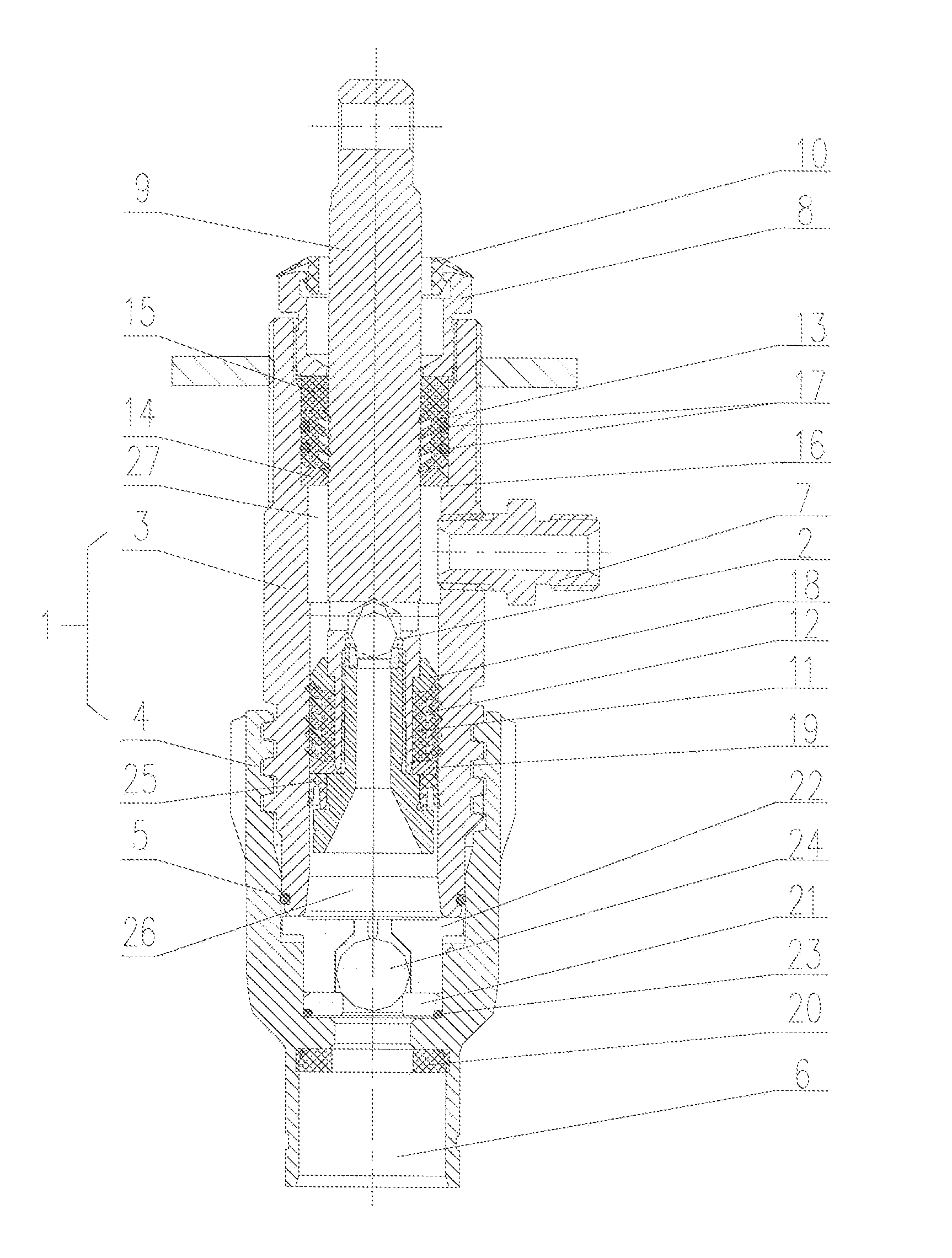
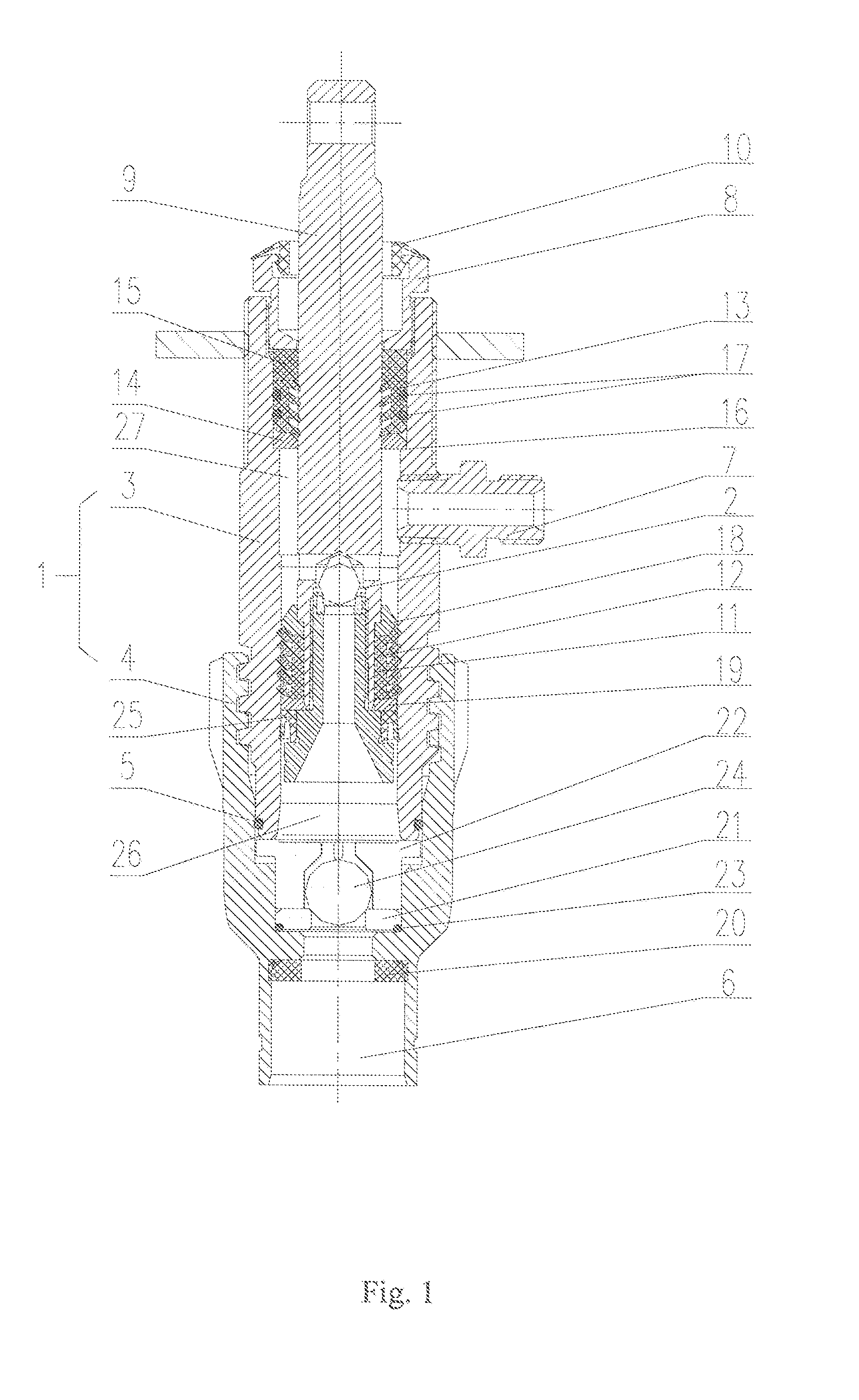
[0013] FIG. 1 is a schematic view of a sealing structure of plunger pump of the present invention.
DETAILED DESCRIPTION OF THE INVENTION
[0014] Referring to FIG. 1, the present invention provides a sealing structure of a plunger pump, comprising a pump body 1 and a plunger rod assembly 2 disposed in the pump body 1. The pump body 1 includes an upper pump 3 and a lower pump 4, and the upper pump 3 and lower pump 4 are fixed by screw connection; a sealing ring 5 provided between the upper pump 3 and the lower pump 4; a feed inlet 6 disposed on the lower pump 4 and a discharge outlet disposed on the upper pump 3; a discharge connector 7 disposed on the discharge outlet; a lock nut 8 disposed at an upper end of the upper pump 3. The plunger rod assembly 2 includes a plunger rod 9 which extends into the pump body 1 through a through hole in the center of the lock nut 8; a dust boot 10 disposed between the plunger rod 9 and the through hole; an annular groove 11 disposed at a position adjacent to a lower portion of the plunger rod 9 at an outer peripheral surface thereof; a dynamic lip seal 12 fitted in the annular groove 11; and a static lip seal 13 sleeved on the outer peripheral surface of the plunger rod 9. The static lip seal 13 having an upper end is disposed on a first seal ring 14 and having a lower end is disposed on a first positioning seat 15. The first positioning seat 15 is disposed on a step of an inner wall of the pump body 1 and the first seal ring 14 is disposed on a bottom surface of the lock nut 8.
[0015] The static lip seal 13 and an inner wall of the upper pump 3 have at least two gasket rings 17 disposed therebetween.
[0016] The dynamic lip seal 12 includes a second seal ring 18 disposed at a top surface thereof and a second positioning seat 19 disposed at a bottom surface thereof; the second seal ring 18 and the second positioning seat 19 are fitted in the annular groove 11 and abutted against top and bottom surfaces of the annular groove 11, respectively.
[0017] The feed inlet 6 of the lower pump 4 includes a feeding seal ring 20 disposed thereon; a feed valve seat 21 disposed at the lower pump 4 adjacent to a bottom surface of the feed inlet 6; a limiting seat 22 attached to the feed valve seat 21; a lower pump sealing ring 23 disposed between the feed valve seat 21 and a bottom surface of the lower pump 4; and a valve ball 24 disposed in an accommodating space which is formed between the limiting seat 22 and the feed valve seat 21.
[0018] The following describes the working principle of the present invention:
[0019] The plunger pump of the present invention, a pumped object is passed through the feed inlet 6 of the lower pump body 4 and into a lower space 26 bounded by a piston 25 of the pump body 1 via the valve ball 24, and enters an upper space 27 bounded by the piston 25 from a passage at the bottom of the plunger rod 9, and is finally discharged from the discharged outlet disposed above the upper space 27 of the pump body 1.
[0020] The above-mentioned process is carried out by reciprocating motion of the plunger rod 9 to drive the piston 25. During the high-speed reciprocating motion, the dynamic lip seal 12 moves up and down with the plunger rod 9 and is always tightly fitted between the plunger rod 9 and the inner wall of the pump body 1, thereby improving the stability of the plunger pump; the static lip seal 13 is provided between the plunger rod 9 and the inner wall of the pump body 1, and the dynamic lip seal 12 is applied so that the sealing effect of the plunger pump is better, and the structure of the dynamic lip seal 12 and the static lip seal 13 allows the plunger pump have a long service life and good anti-wear effect. In addition, it is only necessary to open the upper pump 3 and the lower pump 4 when replacing the dynamic and static lip seal 11, 12, so it is more convenient to replace the parts.
[0021] The above only describes some exemplary embodiments of the present invention. Those having ordinary skills in the art may also make many modifications and improvements without departing from the conception of the invention, which shall all fall within the protection scope of the invention.
* * * * *
D00000
D00001
XML
uspto.report is an independent third-party trademark research tool that is not affiliated, endorsed, or sponsored by the United States Patent and Trademark Office (USPTO) or any other governmental organization. The information provided by uspto.report is based on publicly available data at the time of writing and is intended for informational purposes only.
While we strive to provide accurate and up-to-date information, we do not guarantee the accuracy, completeness, reliability, or suitability of the information displayed on this site. The use of this site is at your own risk. Any reliance you place on such information is therefore strictly at your own risk.
All official trademark data, including owner information, should be verified by visiting the official USPTO website at www.uspto.gov. This site is not intended to replace professional legal advice and should not be used as a substitute for consulting with a legal professional who is knowledgeable about trademark law.