Hydraulic Diaphragm Control
HEMBREE; Richard
U.S. patent application number 15/630314 was filed with the patent office on 2018-12-27 for hydraulic diaphragm control. The applicant listed for this patent is Wanner Engineering, Inc.. Invention is credited to Richard HEMBREE.
| Application Number | 20180372083 15/630314 |
| Document ID | / |
| Family ID | 62873627 |
| Filed Date | 2018-12-27 |


| United States Patent Application | 20180372083 |
| Kind Code | A1 |
| HEMBREE; Richard | December 27, 2018 |
HYDRAULIC DIAPHRAGM CONTROL
Abstract
A diaphragm pump includes a pumping chamber for pumped fluid and a hydraulic chamber. A diaphragm has a pumping chamber side and a hydraulic chamber side. The pumping chamber side of the diaphragm is proximate the pumping chamber and acts on the pumped fluid. The hydraulic chamber side of the diaphragm is proximate the hydraulic chamber. A plunger is in fluid communication with the hydraulic chamber and acts on the hydraulic fluid, which acts on the diaphragm. A plunger driver imparts reciprocal motion to the plunger. The pump includes a sensor assembly sensing position and direction of the plunger and sensing position of the diaphragm. By sensing the position of the diaphragm, hydraulic fluid flow is controlled by a control single valve.
| Inventors: | HEMBREE; Richard; (Port Coquitlam, CA) | ||||||||||
| Applicant: |
|
||||||||||
|---|---|---|---|---|---|---|---|---|---|---|---|
| Family ID: | 62873627 | ||||||||||
| Appl. No.: | 15/630314 | ||||||||||
| Filed: | June 22, 2017 |
| Current U.S. Class: | 1/1 |
| Current CPC Class: | F04B 43/0054 20130101; F04B 2201/0201 20130101; F04B 2201/1208 20130101; F04B 43/0081 20130101; F04B 43/067 20130101 |
| International Class: | F04B 43/02 20060101 F04B043/02; F04B 43/00 20060101 F04B043/00 |
Claims
1. A diaphragm pump comprising: a pumping chamber; a hydraulic chamber; a diaphragm having a pumping chamber side and a hydraulic chamber side, the pumping chamber side being proximate the pumping chamber and the hydraulic chamber side being proximate the hydraulic chamber; a plunger in fluid communication with the hydraulic chamber; a plunger driver imparting reciprocal motion to the plunger; a sensor assembly sensing position and direction of the plunger and sensing position of the diaphragm.
2. The diaphragm pump according to claim 1, further comprising a valve in fluid communication with the hydraulic chamber.
3. The diaphragm pump according to claim 2, wherein the plunger driver comprises a stepper motor.
4. The diaphragm pump according to claim 3, further comprising a controller in communication with the sensor assembly, the stepper motor and the valve, wherein the sensor assembly.
5. The diaphragm pump according to claim 1, wherein the plunger drive comprises a crankshaft and wherein the sensor assembly comprises a first crankshaft sensor sensing position of the crankshaft.
6. The diaphragm pump according to claim 1, wherein the diaphragm comprises a diaphragm rod extending from the hydraulic chamber side and wherein the sensor assembly comprises a sensor sensing a position of the diaphragm rod
7. The diaphragm pump according to claim 1, wherein the diaphragm comprises a diaphragm rod extending from the hydraulic chamber side and wherein the sensor assembly comprises a first sensor and a second sensor spaced apart from the first sensor, the first sensor and the second sensor sensing a position of the diaphragm rod.
8. The diaphragm pump according to claim 1, wherein the diaphragm comprises a diaphragm rod extending from the hydraulic chamber side and wherein the sensor assembly comprises a linear variable differential transformer (LVDT) sensing a position of the diaphragm rod.
9. The diaphragm pump according to claim 1, wherein the plunger drive comprises a crankshaft and wherein the sensor assembly comprises a first crankshaft sensor sensing position of the crankshaft and a second crankshaft sensor sensing the position of the crankshaft.
10. A diaphragm pump sensing and control system, the diaphragm pump comprising a diaphragm, a hydraulic fluid chamber and a plunger acting on the hydraulic fluid chamber; the diaphragm pump sensing system comprising: a first sensor sensing position and direction of the plunger; and a second sensor sensing position of the diaphragm; a single valve controlling fluid flow into and out of the hydraulic fluid chamber.
11. A method for controlling a diaphragm pump, the diaphragm pump comprising a diaphragm, a fluid chamber containing hydraulic fluid acting on the diaphragm, a plunger in fluid communication with the fluid chamber, and a single valve controlling flow into and out of the fluid chamber, the method comprising: sensing position and direction of the plunger; sensing position and direction of movement of the diaphragm;
Description
BACKGROUND OF THE INVENTION
Field of the Invention
[0001] The present invention is directed to a system for controlling a diaphragm in a diaphragm pump using a solenoid valve and to a pump including a system using a solenoid valve to control the diaphragm.
Description of the Prior Art
[0002] Diaphragm pumps are pumps in which the pump fluid is displaced by a diaphragm. In hydraulically driven pumps, the diaphragm is deflected by hydraulic fluid pressure forced against the diaphragm, which acts against the pumped fluid in a reciprocating motion. Typically, a plunger moves in a reciprocating manner in a cylinder to act against the hydraulic fluid and force the fluid against the diaphragm. The hydraulic fluid flow is controlled by a system of valves. Such control systems for diaphragm pumps are shown in U.S. Pat. No. 4,665,974 and U.S. Pat. No. 7,425,120. Such a control system has three main valves for each cylinder including a spool valve, a check valve that relieves fluid in an over filled condition, and a check valve utilized for adding fluid in an under filled condition. For each of the check valves, a spool valve depending on the diaphragm position is utilized for actuation. In addition, such diaphragm pumps also typically require a fourth valve used as an air bleed valve that allows air to exit the hydraulic chamber such as may occur during priming.
[0003] Although such pumps and such control systems are generally efficient and reliable, the valves are relatively costly and require an interrelationship to maintain the proper fluid level and pressure. Moreover, the pump must be configured with a hydraulic chamber that allows for correct placement and interrelationship of the various valves and their associated fluid conduits.
[0004] It can be seen that a new and improved pump and control system are needed that eliminate one or more of the hydraulic fluid valves in a diaphragm pump and provide reliable pumping and control at a reduced cost. In particular, the reduction in the number of valves and sensors to a single solenoid valve is desirable. The present invention addresses these problems as well as others associated with diaphragm pumps and diaphragm position control.
SUMMARY OF THE INVENTION
[0005] The present invention is directed to a diaphragm pump, and in particular to a diaphragm pump with a control system that utilizes a single valve to control fluid levels in the hydraulic chamber. The diaphragm is driven by a plunger connected to a crankshaft or other drive. The diaphragm includes a non-magnetic rod connecting to an iron rod that is sensed by one or more proximity sensors.
[0006] The present invention includes a single solenoid valve connected to the hydraulic chamber that controls hydraulic fluid flow into or out of the hydraulic chamber to correct an overfill condition or underfill condition. In different embodiments, the plunger may be driven by a crankshaft that may include a proximity sensor sensing indicator lobes of the crankshaft. In other embodiments, the plunger may be driven by a lead screw and stepper motor.
[0007] The iron rod connected to the diaphragm may include a single sensor working in conjunction with sensors on the lobes of the crankshaft or may include two proximity sensors to detect the position of the iron rod and therefore the position of the diaphragm. In another embodiment, a linear variable differential transformer accurately detects the position of the iron rod and therefore the position of the diaphragm. In each embodiment, the sensors and sensing circuit and/or controller are able to determine whether the plunger has gone beyond top dead center or bottom dead center and whether there is an underfilled condition or an overfilled condition. When this occurs, the single solenoid valve may be opened or closed to correct the underfilled or overfilled condition. The use of multiple sensors eliminates the need for more than one hydraulic fluid control valve.
[0008] These features of novelty and various other advantages that characterize the invention are pointed out with particularity in the claims annexed hereto and forming a part hereof. However, for a better understanding of the invention, its advantages, and the objects obtained by its use, reference should be made to the drawings that form a further part hereof, and to the accompanying descriptive matter, in which there is illustrated and described a preferred embodiment of the invention.
BRIEF DESCRIPTION OF THE DRAWINGS
[0009] Referring now to the drawings, wherein like reference letters and numerals represent corresponding structure throughout the several views:
[0010] FIG. 1 is a schematic view of a diaphragm pump with a first embodiment of a sensing system;
[0011] FIG. 2 is a logic and wiring diagram for the diaphragm pump shown in FIG. 1;
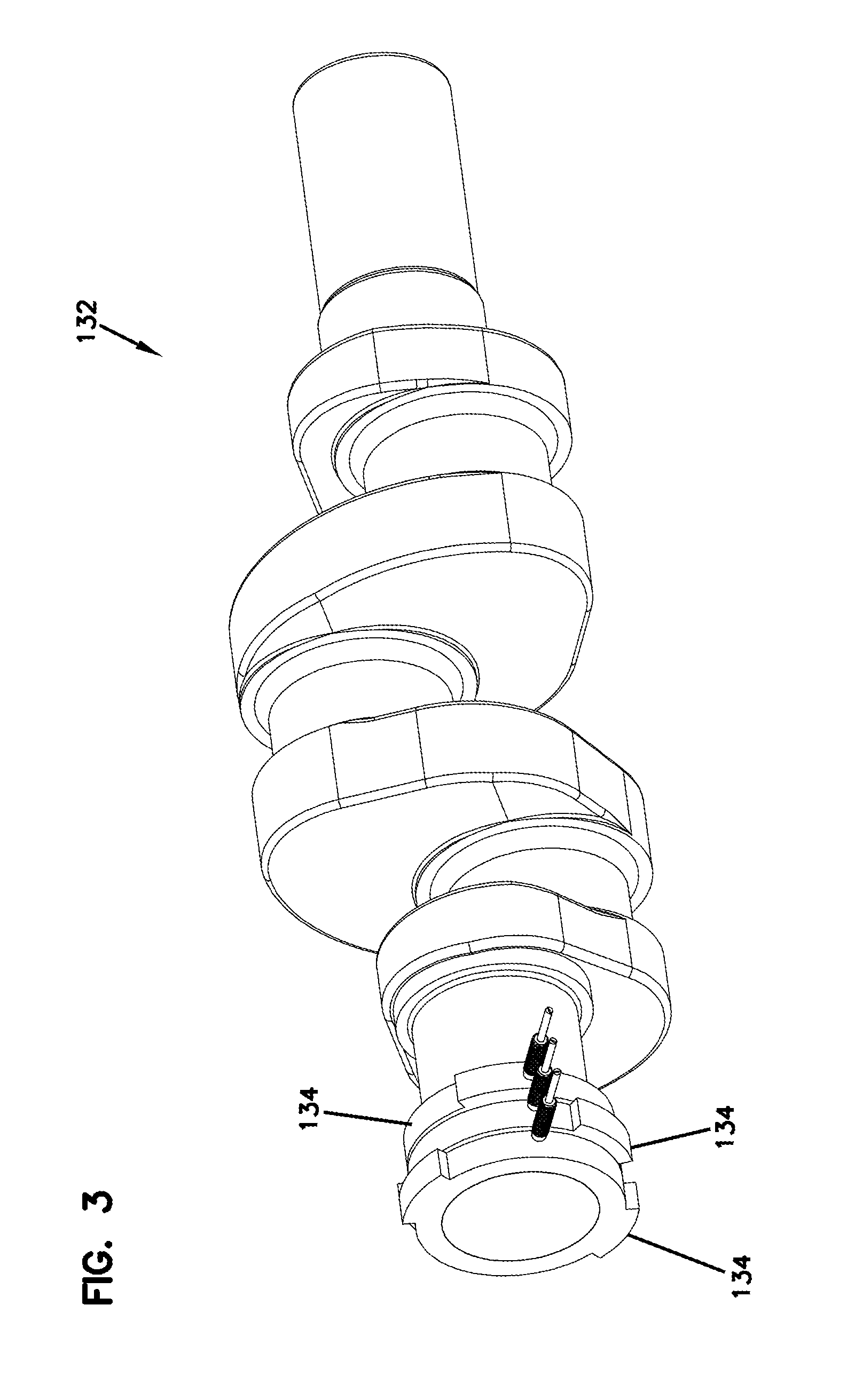
[0012] FIG. 3 is a crankshaft for a 3 cylinder pump such as the pump shown in FIG. 1 with a sensor and indicator lobes for each cylinder;
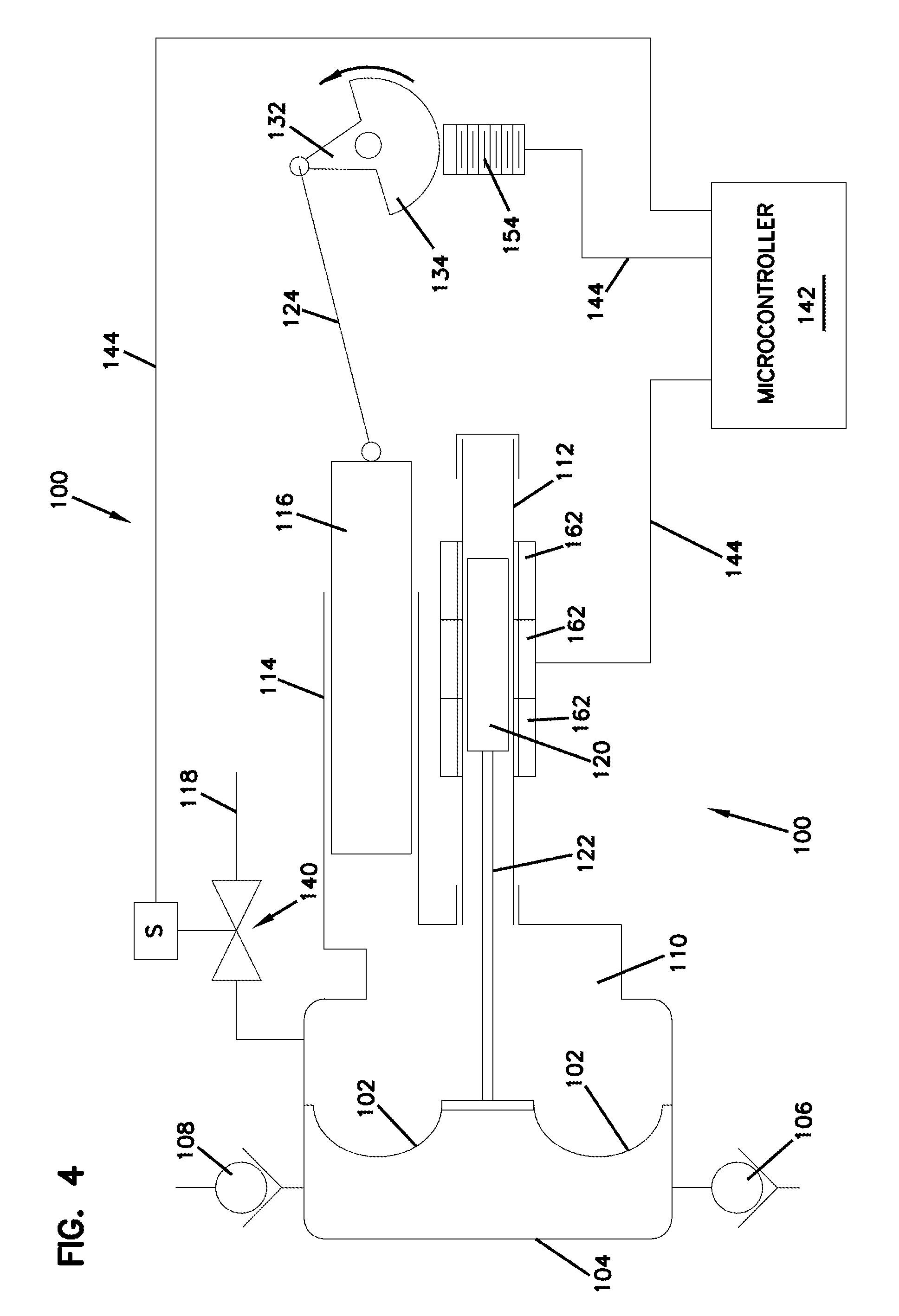
[0013] FIG. 4 is a schematic view of diaphragm pump with a second embodiment of a sensing system;
[0014] FIG. 5 is a schematic view of a diaphragm pump with a third embodiment of a sensing system;
[0015] FIG. 6 is a schematic view of a diaphragm pump with a fourth embodiment of a sensing system;
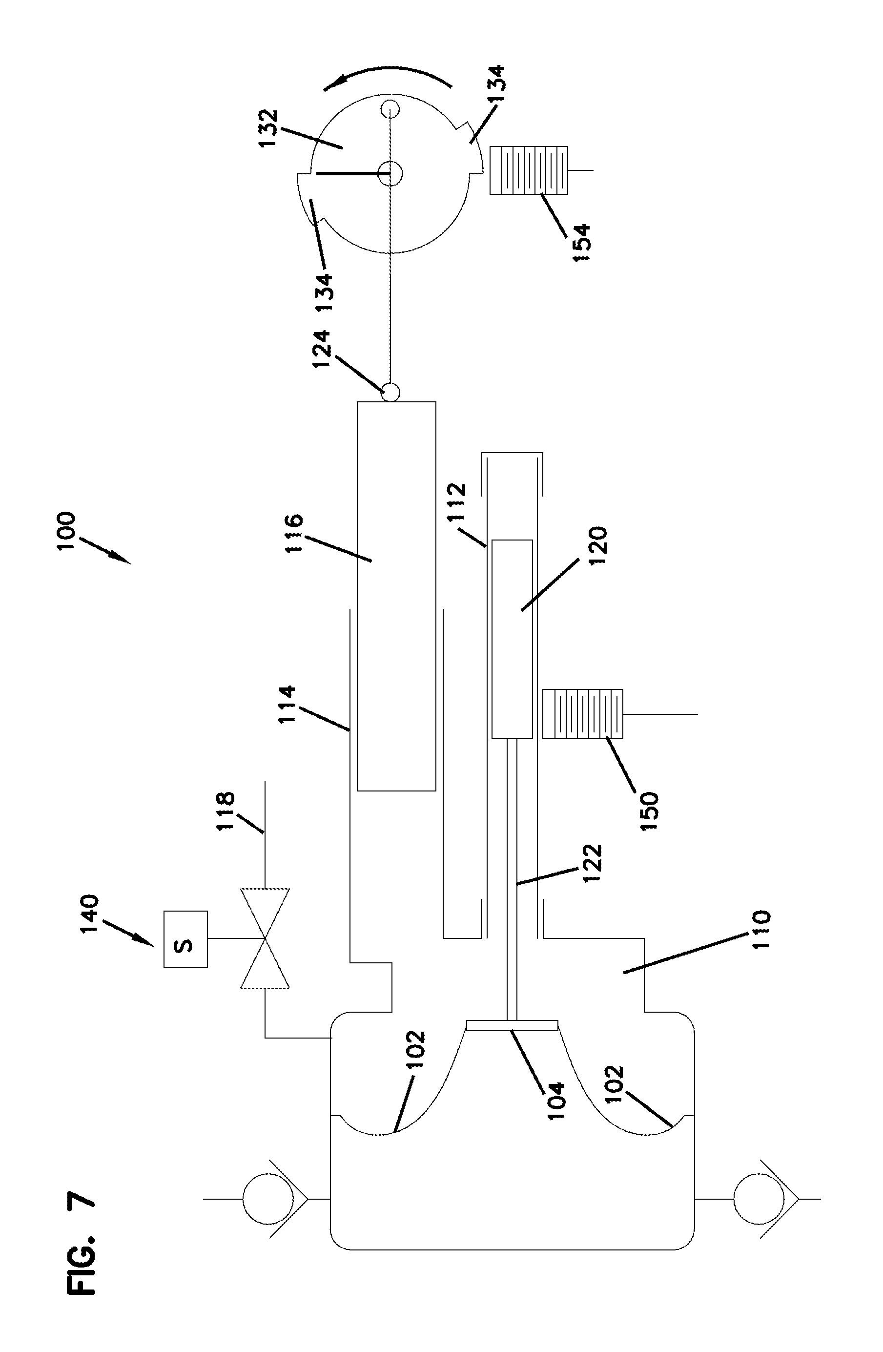
[0016] FIG. 7 is a schematic view of the diaphragm pump of FIG. 1 with the diaphragm in the bottom dead center (BDC) position;
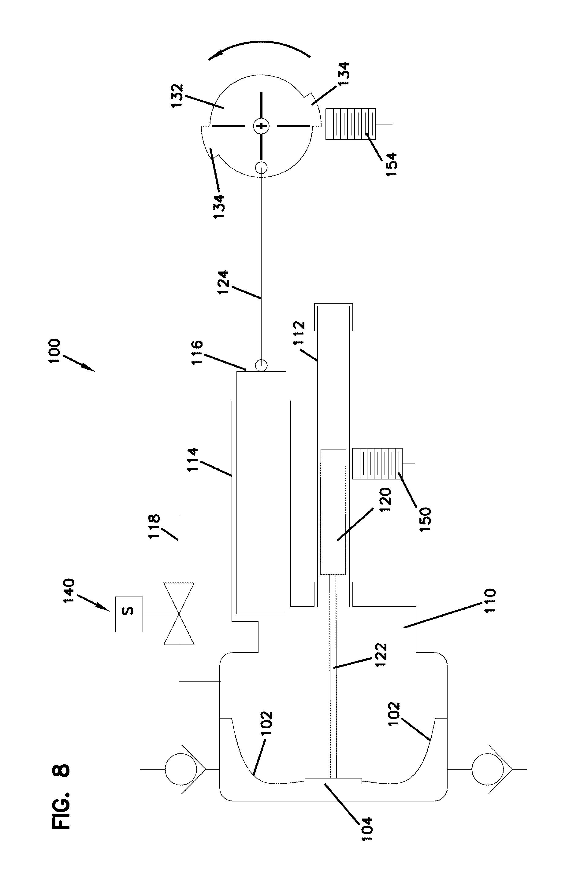
[0017] FIG. 8 is a schematic view of the diaphragm pump of FIG. 1 with the diaphragm in the top dead center (TDC) position;
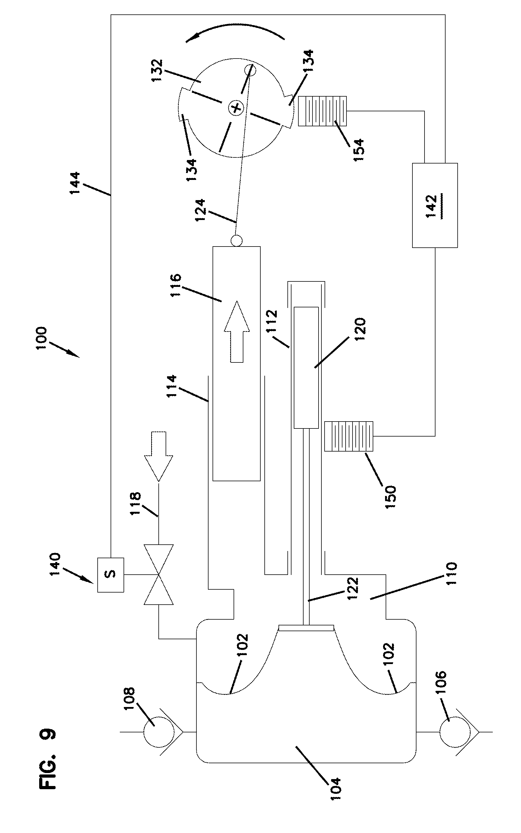
[0018] FIG. 9 is a schematic view of the diaphragm pump of FIG. 1 with the solenoid open to add fluid to the under-filled hydraulic fluid chamber at BDC; and
[0019] FIG. 10 is a schematic view of the diaphragm pump of FIG. 1 with the solenoid open to dump fluid from the over-filled hydraulic fluid chamber at TDC.
DETAILED DESCRIPTION OF THE PREFERRED EMBODIMENT
[0020] Referring now to the drawings, and in particular FIG. 1, there is shown a pump, generally designated (100). In particular, the pump (100) may be a diaphragm pump including a deformable diaphragm (102). The diaphragm (102) is deformed to act on pumped fluid in a fluid chamber (104). Flow into and out of the pumped fluid chamber (104) is controlled by an inlet check valve (106) and an outlet check valve (108). A hydraulic chamber (110) filled with hydraulic fluid is on the opposite side of the diaphragm (102). A plunger (116) reciprocates in a cylinder (114) to act on the hydraulic fluid, which acts on the diaphragm (102) to force pumped fluid out as shown in FIG. 10 or to draw pump fluid in as shown in FIG. 9. The cylinder (116) is driven by a crankshaft (132) through a connecting linkage (124).
[0021] The pump (100) also includes a tube (112) connected to the hydraulic chamber (110). The tube (112) is made of a non-metallic material so as not to be affected by magnetics does not affect sensors able to sense magnetic materials. The opposite end of the tube (112) is closed to complete a hydraulic space. The diaphragm (102) is connected to a non-metallic rod (122). An iron rod (120) mounts to the non-metallic rod (122) and reciprocates as the diaphragm (102) is moved outward into the pumping chamber (104) and retracted back against the hydraulic fluid in the hydraulic fluid chamber (110).
[0022] In a first embodiment, a proximity sensor (150) is located proximate the tube (112) so that the sensor (150) can sense the iron rod (120) inside the tube (112). The rod (122) and the tube (112) are both made from materials that the sensor (150) will not detect. It will be appreciated that the sensor (150) may be an inductive type sensor able to detect the iron rod (120) but not the connecting rod (122). The sensor (150) is positioned so as to detect the rod (120) when the diaphragm (102) is at any position along its normal operating stroke. When the diaphragm (102) travels beyond top dead center when the hydraulic chamber (110) is in the over-filled condition, or beyond bottom dead center when the hydraulic chamber (110) is in the under-filled condition, the sensor (150) does not detect the iron rod (120). This information is passed along to a controller (142).
[0023] The pump (100) uses a single solenoid valve (140) connected to the hydraulic chamber (110) to control hydraulic fluid flow. In a preferred embodiment, the solenoid valve (140) is near the top of the hydraulic chamber (110) so that air can exit the hydraulic chamber (110) through the valve (140). The other port from the valve (140) is connected to a fluid sump by tubing (118). The end of the tubing (118) should be positioned below the surface of the fluid so that fluid can either exit or enter the tubing (118).
[0024] In the embodiment shown in FIG. 1, the pump control system also includes a second set of proximity sensors (154) proximate the crankshaft (132). The crankshaft (132) includes lobes (134). The lobes (134) are positioned so that when sensed by sensor (154), the diaphragm is at either top dead center or bottom dead center. The lobes (134) are positioned so that as soon as the crank passes top dead center or bottom dead center, the sensor (154) stops detecting the lobes (134). An embodiment of the crankshaft (132) is shown in greater detail in FIG. 3. The crankshaft (132) includes lobes (134) for each cylinder in a three cylinder pump.
[0025] Referring now to FIG. 2, there is shown a circuit diagram for the control circuit (144). The control circuit (144) is connected to the solenoid valve (140) as well as the proximity sensors (150 and 154). Switches (170 and 172) are energized or de-energized by the respective sensor (150 or 154) to open or close the circuit (144) and therefore open or close the valve (140). Simple and reliable control is therefore obtained with the circuit (144) requiring only two switches (170 and 172).
[0026] The control circuit (144) connects to the proximity sensors (150 and 154) and to the solenoid valve (140) and may also connect to a microcontroller (142). Opening and closing of the solenoid valve (140) is controlled by the positions detected by the proximity sensors (150 and 154). It can be appreciated that the relay energized by the sensor (150) is normally closed so that when the sensor (150) detects the rod (120) in normal operation, the circuit (144) is open.
[0027] Referring now to FIG. 4, there is shown a second embodiment of the pump (100). The pump shown in FIG. 4 is similar to that shown in FIG. 1 but the pump utilizes a linear variable differential transformer (LVDT) to detect the iron rod (120). In the embodiment shown, the LVDT includes three coils (162) that surround the fiberglass tube (112). Use of the LVDT avoids having electrical coils immersed in the fluid of the hydraulic chamber (110). This configuration also avoids feeding wires into the cycling high pressure of the chamber (110), which may be difficult and complicated. The LVDT also provides a signal indicating the position of the diaphragm (102) throughout the stroke and achieves precise timing for opening of the valve (140).
[0028] Referring now to FIG. 5, there is shown a third embodiment of a diaphragm pump. In the embodiment of FIG. 5, the plunger (116) is driven by a linear drive (182) such as a lead screw and a stepper motor (180) that may be controlled by a controller (142). As the microcontroller (142) knows the position and direction of the plunger from inputs from the stepper motor (180), the microcontroller can therefore infer/determine the proximate position of the diaphragm. Therefore, only one proximity sensor is required to indicate an under-fill or an over-fill condition. The proximity sensor (150) is placed mid stroke of the iron rod (120). Therefore, when the stroke of the diaphragm (102) exceeds the normal range in either direction, the sensor (150) signals the microcontroller (142). In response to the sensed under-fill or over-fill condition, the microcontroller (142) will open the solenoid valve (140) at an appropriate time to restore normal operating conditions.
[0029] Referring now to FIG. 6, there is shown a fourth embodiment of a pump. In the embodiment shown in FIG. 6, the pump (100) utilizes two proximity sensors (150 and 152) to detect the position of the diaphragm. The sensor (152) acts as an under-fill sensor and detects the position of an iron rod (120). By using two sensors (150 and 152) to detect the position of the rod (120), the controller (142) will be able to determine whether the diaphragm is beyond the top dead center over-filled condition or beyond the bottom dead center under-filled position regardless of the position of the plunger (116). With the two spaced apart proximity sensors (150 and 152), only the direction of the plunger (160) is needed rather than the position of the crank (132) relative to top dead center or bottom dead center.
[0030] It can be appreciated that the operation of the solenoid valve operates in four main modes. The logic used to open the solenoid valve (140) is similar in each of the four embodiments. However, the general operation is described with respect to the embodiment of FIG. 1 even though applicable to the other embodiments. In a first mode, the pump is in a normal operating mode. In a second mode, the pump is in an under-filled operating mode. In a third mode, the pump is in an over-filled operating mode, and in a fourth mode, the pump is in a priming condition. The first mode is shown in FIGS. 7 and 8. In the first operating mode, the pump (100) has the correct amount of fluid in the hydraulic chamber (110). The pump (100) is shown with the diaphragm (102) and the plunger (116) at bottom dead center in FIG. 7. At this position, the sensor (150) still detects the rod (120) so the solenoid valve (140) remains closed. With the pump (100) shown with the diaphragm (102) and the plunger (116) at top dead center in FIG. 8, the sensor (150) detects the iron rod (120) and the solenoid valve (140) remains closed.
[0031] As shown in FIG. 9, in the second mode, the plunger (116) is approaching bottom dead center but the diaphragm (102) has passed beyond the normal bottom dead center and the proximity sensor (150) is not sensing the rod (120). The control circuit (144) opens the solenoid valve (140). As the plunger (116) continues to bottom dead center, hydraulic fluid is drawn into the hydraulic chamber (110). The solenoid valve (140) closes once the sensor (154) senses that the plunger (116) has reached bottom dead center and is beginning the forward pressure stroke.
[0032] As shown in FIG. 10, in the third operating mode, the plunger (116) is approaching top dead center but the diaphragm (102) has gone beyond the normal top dead center position and the proximity sensor (150) is not sensing the rod (120). A microcontroller or the control circuit (144) opens the solenoid valve (140). As the plunger (116) continues to top dead center, hydraulic fluid is dumped from the hydraulic chamber (110). Once the plunger (116) is at top dead center, the second set of proximity sensors (154) senses top dead center from the lobes (134) and shuts the valve (140) for the suction stroke.
[0033] The fourth mode takes place when the pump (100) is first assembled and hydraulic oil needs to be primed into the hydraulic chamber (110). In this scenario, the solenoid valve (140) is held open for several strokes by the microcontroller regardless of input from the sensors (150 and 154) to purge air from the hydraulic chamber (110). After several strokes, the valve (140) is closed and depending on which mode the pump is in after the solenoid valve (140) is closed, the oil level in the hydraulic chamber (110) will be automatically adjusted by the controller to return to normal.
[0034] It can be appreciated that the present invention achieves improved control utilizing sensors to detect the true position of the diaphragm. Control of the fluid levels is accomplished with a single solenoid valve (140) and eliminates the need for multiple valves associated with the hydraulic chamber as is required with the prior art. The present invention achieves greater reliability and is less expensive and easier to manufacture and maintain.
[0035] It is to be understood, however, that even though numerous characteristics and advantages of the present invention have been set forth in the foregoing description, together with details of the structure and function of the invention, the disclosure is illustrative only, and changes may be made in detail, especially in matters of shape, size and arrangement of parts within the principles of the invention to the full extent indicated by the broad general meaning of the terms in which the appended claims are expressed.
* * * * *
D00000
D00001
D00002
D00003
D00004
D00005
D00006
D00007
D00008
D00009
D00010
XML
uspto.report is an independent third-party trademark research tool that is not affiliated, endorsed, or sponsored by the United States Patent and Trademark Office (USPTO) or any other governmental organization. The information provided by uspto.report is based on publicly available data at the time of writing and is intended for informational purposes only.
While we strive to provide accurate and up-to-date information, we do not guarantee the accuracy, completeness, reliability, or suitability of the information displayed on this site. The use of this site is at your own risk. Any reliance you place on such information is therefore strictly at your own risk.
All official trademark data, including owner information, should be verified by visiting the official USPTO website at www.uspto.gov. This site is not intended to replace professional legal advice and should not be used as a substitute for consulting with a legal professional who is knowledgeable about trademark law.