A Method And A System For Mounting A Rotor To A Drive Shaft Of A Wind Turbine
Pedersen; Gunnar K. Storgaard
U.S. patent application number 16/060092 was filed with the patent office on 2018-12-27 for a method and a system for mounting a rotor to a drive shaft of a wind turbine. The applicant listed for this patent is Vestas Wind Systems A/S. Invention is credited to Gunnar K. Storgaard Pedersen.
| Application Number | 20180372063 16/060092 |
| Document ID | / |
| Family ID | 59089164 |
| Filed Date | 2018-12-27 |


| United States Patent Application | 20180372063 |
| Kind Code | A1 |
| Pedersen; Gunnar K. Storgaard | December 27, 2018 |
A METHOD AND A SYSTEM FOR MOUNTING A ROTOR TO A DRIVE SHAFT OF A WIND TURBINE
Abstract
A method for mounting a rotor to a drive shaft of a wind turbine, the method comprising placing a hub on a surface, attaching a first, a second, and a third rotor blade to the hub to thereby make a rotor in situ. To protect the blades and to avoid fixed lifting lugs on the rotor, the method includes the step of wrapping a sling about each of the blades, attaching each sling to a fitting, lifting each fitting to thereby raise the rotor from the surface, and attaching the rotor to the drive shaft while the position and orientation of the rotor is controlled by the slings.
| Inventors: | Pedersen; Gunnar K. Storgaard; (Skjern, DK) | ||||||||||
| Applicant: |
|
||||||||||
|---|---|---|---|---|---|---|---|---|---|---|---|
| Family ID: | 59089164 | ||||||||||
| Appl. No.: | 16/060092 | ||||||||||
| Filed: | December 19, 2016 | ||||||||||
| PCT Filed: | December 19, 2016 | ||||||||||
| PCT NO: | PCT/DK2016/050444 | ||||||||||
| 371 Date: | June 7, 2018 |
| Current U.S. Class: | 1/1 |
| Current CPC Class: | Y02E 10/72 20130101; Y02E 10/721 20130101; F03D 1/06 20130101; F03D 13/10 20160501; B66C 1/18 20130101; Y02P 70/523 20151101; F03D 1/0658 20130101; Y02P 70/50 20151101; B66C 1/108 20130101; B66C 1/12 20130101; F05B 2230/61 20130101 |
| International Class: | F03D 1/06 20060101 F03D001/06; F03D 13/10 20060101 F03D013/10; B66C 1/10 20060101 B66C001/10; B66C 1/18 20060101 B66C001/18 |
Foreign Application Data
| Date | Code | Application Number |
|---|---|---|
| Dec 22, 2015 | DK | PA 2015 70863 |
Claims
1. A method for mounting a rotor to a drive shaft of a wind turbine, the method comprising placing a hub on a surface, attaching a first, a second, and a third rotor blade to the hub to thereby make a rotor in situ, wrapping a sling about each of the blades, attaching each sling to a fitting, lifting each fitting to thereby raise the rotor from the surface, and attaching the rotor to the drive shaft while the position and orientation of the rotor is controlled by the slings.
2. The method according to claim 1, wherein at least one of the slings is wrapped more than 360 degrees about a rotor blade.
3. The method according to claim 1, wherein the orientation of the rotor is controlled by changing the distance from the fitting to one of the rotor blades which thereby becomes a controlled rotor blade.
4. The method according to claim 3, wherein the distance from the fitting to the controlled rotor blade is changed by changing the distance between the fitting and that sling which is wrapped about the controlled blade, the sling thereby becoming a controlled sling.
5. The method according to claim 3, wherein the distance is changed by use of a power driven actuator.
6. The method according to claim 1, wherein at least one sling is attached to the fitting via a pulley block.
7. The method according to claim 5 wherein the power driven actuator is attached between the fitting and the pulley block of the controlled sling.
8. The method according to claim 4, wherein the rotor is protected against contact with the controlled sling by a shield (18) which is removed from the rotor when the rotor is mounted to the drive shaft.
9. The method according to claim 8, wherein the shield is held by the controlled sling.
10. The method according to claim 1, wherein all slings are attached to a single fitting.
11. The method according to claim 1, wherein all slings are assembled in one point where they are attached to the fitting.
12. The method according to claim 1, wherein the rotor forms a flange for attachment to the drive shaft and thereby defines a rotor axis about which the rotor is configured to rotate when attached to the drive shaft, and where the rotor is carried by a stand on the surface such that the flange is lifted from the surface.
13. The method according to claim 4, wherein the controlled sling is wrapped one turn about the controlled blade and the other slings are wrapped two turns about the corresponding blades.
14. The method according to claim 4, wherein the controlled sling is connected to an actuator without a pulley block and the other slings are connected to the fitting via a pulley block.
15. A system for mounting a rotor to a drive shaft of a wind turbine, the system comprising at least three slings each being suitable for being wrapped about a blade, a fitting for attaching the slings to a crane cable, and an actuator for changing the distance between the fitting and one of the slings to thereby enable controlling of the orientation of a rotor which is lifted by a sling about each blade.
16. The system according to claim 14, further comprising a shield which is attachable to the rotor or to one of the slings and which is suitable for protecting the rotor against contact with a sling.
17. The system according to claim 16, wherein the shield forms a curved track for receiving one of the slings during reorientation of the rotor.
Description
TECHNICAL FIELD
[0001] The present invention relates to manufacturing of wind turbines, and particularly to a method and a system for mounting a rotor to a drive shaft of a wind turbine.
[0002] Wind turbines, particularly horizontal axis wind turbines, comprise a tower and a nacelle, the nacelle is typically rotatable at a top end of the tower and carries a drive shaft and a rotor. The rotor drives a drive shaft which again drives a power generator for generating electrical power.
[0003] The rotor comprises a hub and a number of blades attached to the hub. Additionally, the rotor may comprise a spinner forming an aerodynamic tip facing the wind in front of the hub.
[0004] Recently, the size of wind turbines has increased with the growing demand for power and efficiency Modern wind turbines are very large, and the rotor may span more than hundred meters. Typically, the wind turbines are made on location by erecting a tower and lifting the nacelle without the rotor to the tower top. This operation is carried out by use of a crane. The hub is often lifted in one piece and attached to the rotor shaft. Subsequently, each blade is lifted individually and attached to the hub.
[0005] The lifting operation is normally complex and expensive, not least due to the need for very large cranes.
DESCRIPTION OF THE INVENTION
[0006] It is an object of embodiments of the invention to reduce the complexity in wind turbine manufacturing, particularly related to handling and attachment of the rotor to the rotor shaft.
[0007] According to this and other objects, the invention, in a first aspect, provides a method for mounting a rotor to a drive shaft of a wind turbine, the method comprising placing a hub on a surface, attaching a first, a second, and a third rotor blade to the hub to thereby make a rotor in situ, wrapping a sling about each of the blades, attaching each sling to a fitting, lifting each fitting to thereby raise the rotor from the surface, and attaching the rotor to the drive shaft while the position and orientation of the rotor is controlled by the slings.
[0008] In a second aspect, the invention provides a system for mounting a rotor to a drive shaft of a wind turbine, the system comprising at least three slings each being suitable for being wrapped about a blade, a fitting for attaching the slings to a crane cable, and an actuator for changing the distance between the fitting and one of the slings to thereby enable controlling of the orientation of a rotor which is lifted by a sling about each blade.
[0009] Since the rotor is lifted by slings about each of the blades, the rotor can be lifted efficiently and safely without having to rig the rotor with fixed lifting lugs and other equipment which will have to be removed after the lifting operation. Accordingly, the lifting operation can be finalised simply by releasing the slings. This can be done remotely, or at least without having to carry out time consuming or expensive repair work on the rotor in an attempt to remove fixed lifting lugs.
[0010] Since the process requires no amendment of the rotor with fixed lifting lugs, the process leaves no visual marks on the rotor.
[0011] Herein, the term "rotor" is used to express the unit attached to the drive shaft and comprising the hub, the blades and optionally additional component such as blade pitching components, spinner, lightening protecting components etc.
[0012] The term "shaft" expresses the drive shaft of the wind turbine, i.e. that shaft being driven by the rotor and which drives a power generator or other components e.g. through a gearbox.
[0013] The wind turbine to which the invention relates may be a horizontal or near horizontal axis wind turbine, and particularly a wind turbine of the kind where the rotor comprises three blades offset in the range of 120 degrees relative to each other. The invention is particularly useful in large wind turbines, e.g. in wind turbines having an effect above 1 MW or even above 2 or 3 MW.
[0014] Particularly, the invention may be used in combination with nacelle constructions where the nacelle is rotatable relative to the tower to thereby let the rotor face the wind. In such wind turbines, the turbine noise emission may be in any direction depending on the wind, and the masking sound may efficiently reduce particularly the tonal component of the turbine noise.
[0015] The step of attaching the rotor to the drive shaft is performed in a standard procedure known in the art, however, during this procedure the position and orientation of the rotor is controlled by the slings. Particularly, the method may depend entirely on the slings to hold and orient the rotor such that no other elements are applied. Particularly, the method may be carried out without bolting, welding or otherwise fixing elements to the rotor.
[0016] To improve the ability to reorient the rotor by use of the slings and to prevent slipping between the slings and the blades, at least one of the slings and preferably all slings may be wrapped two or more turns around the blade, i.e. more than 360 degrees about a rotor blade.
[0017] The orientation of the rotor may be controlled by changing the distance from the fitting to one of the rotor blades. This rotor blade will in the following be referred to as "a controlled rotor blade". The distance may e.g. be varied within the range of 50-150 percent of the distance between the fitting and the other blades, such as in the range between 75-125 percent.
[0018] The distance from the fitting to the controlled rotor blade can be changed by changing the distance between the fitting and that sling which is wrapped about the controlled blade or by changing the length of that sling. In the following we refer to this sling as "a controlled sling".
[0019] The distance could be changed by use of a power driven actuator, e.g. a hydraulic or electric linear actuator.
[0020] At least one sling, and preferably all slings may be attached to the fitting via a pulley block allowing the slings to roll back and forth independent on the orientation of the fitting. In one embodiment, the pulley block may be controllable, e.g. so that that each pulley block can be blocked independently to prevent individual slings from moving relative to the fitting.
[0021] The power driven actuator could be attached between the fitting and the pulley block of the controlled sling such that the sling can move relative to the power driven actuator through the pulley block.
[0022] The rotor could be protected against contact with the controlled sling by a shield which is removed from the rotor when the rotor is mounted to the drive shaft. The shield may particularly cover a portion of the tip of the hub or it may cover a portion of a spinner, if a spinner is attached to the hub.
[0023] The shield may e.g. form a sheet of metal, composite, or plast-material. The shield may e.g. be held in place by the controlled sling, or it may be held in place by other means, e.g. adhesively to an outer surface of the hub or spinner, or by straps etc.
[0024] All slings could be attached to a single fitting, and all slings may particularly be lifted from one single location. As an example, the fitting may assemble all slings in one single point from which the crane cable can lift the rotor. In this way, the slings may form a relatively large angle to each other, e.g. an angle above 10 degrees.
[0025] In an alternative embodiment, the slings may be held e.g. by a lifting lug at distance from each other. In that way, the slings may extend with a smaller angle relative to each other, e.g. below 10 degrees, or even parallel to each other.
[0026] All slings may be attached to a single fitting which is again lifted e.g. by a crane cable.
[0027] The rotor typically forms a flange for attachment to the drive shaft and thereby defines a rotor axis about which the rotor is configured to rotate when attached to the drive shaft. the method according to this invention may include using a stand for the rotor such that the rotor and particularly the flange is lifted from the surface. This not only facilitates wrapping the slings about the blades, it also protects the blades against contact with the surface or ground if the rotor tilts slightly.
[0028] In a second aspect, a system for mounting a rotor to a drive shaft of a wind turbine is provided. The system comprises a sling for each blade of the rotor, a fitting for attaching the slings to a crane cable, and an actuator for changing the distance between the fitting and one of the slings to thereby enable controlling of the orientation of a rotor which is lifted by a sling about each blade. The fitting may e.g. be a crane hook, and the actuator may be a hydraulic actuator.
[0029] The system may further comprise a shield which is attachable to the rotor or to one of the slings and which is suitable for protecting the rotor against contact with a sling. The shield may a curved track for receiving one of the slings during reorientation of the rotor. The shield may particularly be a sheet of a steel, composite, or plastic material, and the curved track may be formed by the shape of the shield. Particularly, the track may e.g. be formed by bended edge portions of the shield such that the controlled sling is held on the shield between the bended edges.
DETAILED DESCRIPTION OF THE DRAWINGS
[0030] The invention will now be described in further details with reference to the accompanying drawings, wherein:
[0031] FIG. 1 illustrates a wind turbine with a tower and a nacelle;
[0032] FIG. 2 illustrates a rotor placed on ground in a stand ready to be lifted;
[0033] FIG. 3 illustrates the rotor when lifted free from the stand;
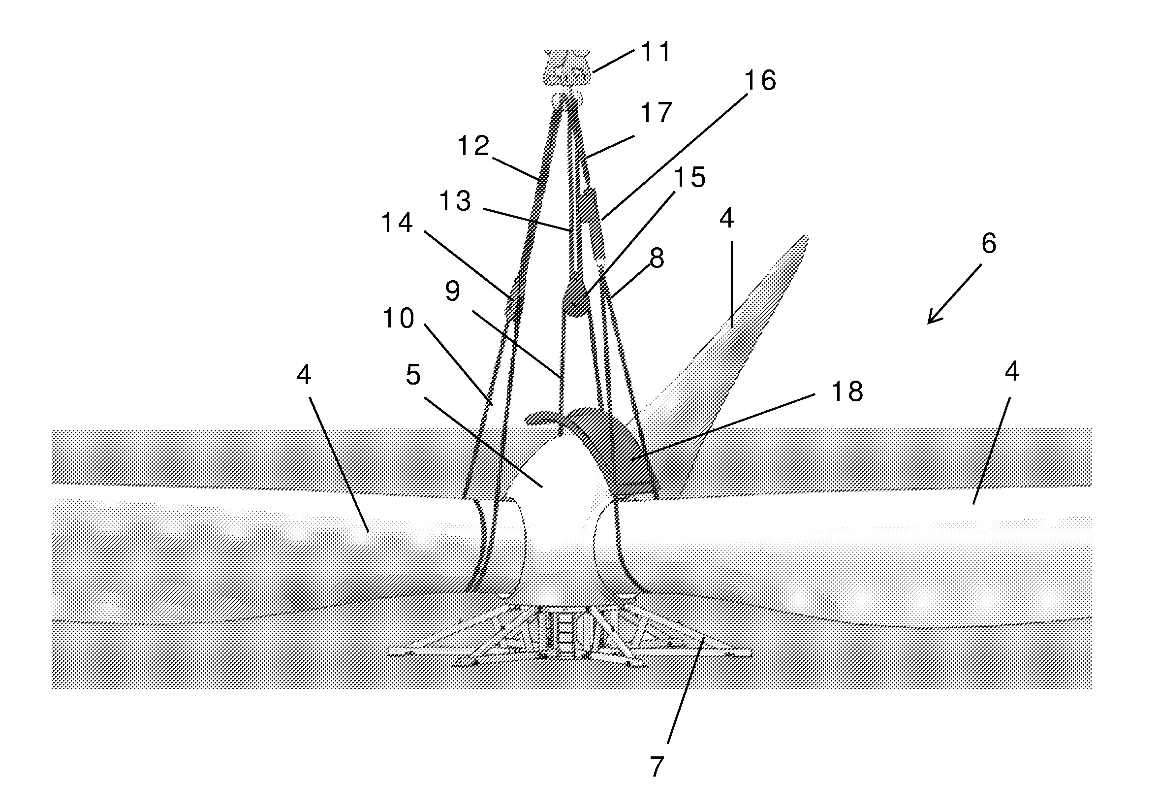
[0034] FIG. 4 illustrates the step of reorienting the rotor by use of an actuator extending the distance from the fitting to the controlled blade;
[0035] FIG. 5 illustrates the rotor in an orientation ready for attachment to a drive shaft; and
[0036] FIG. 6 illustrates an embodiment of the controlled sling.
[0037] Further scope of applicability of the present invention will become apparent from the following detailed description and specific examples. However, it should be understood that the detailed description and specific examples, while indicating preferred embodiments of the invention, are given by way of illustration only, since various changes and modifications within the scope of the invention will become apparent to those skilled in the art from this detailed description.
[0038] FIG. 1 illustrates a wind turbine 1 with a tower 2, a nacelle 3, a rotor including three blades 4 and a hub covered with a spinner 5
[0039] FIG. 2 illustrates the rotor 6 of the wind turbine before it is attached to the drive shaft in the nacelle. The rotor comprises a hub covered by a spinner 5 and the three blades 4. The rotor is placed in a stand 7 on ground surface.
[0040] A first, second, and third sling 8, 9, 10 is wrapped about the blades. The slings are attached to a fitting, in this embodiment in the form of a lifting hook 11. Two of the slings are connected to the hook via robes 12, 13 and the pulley blocks 14, 15. The last sling 8, herein referred to as the controlled sling, is connected to the fitting via an actuator 16 and a robe 17.
[0041] Two of the slings 9, 10 are wrapped two turns around the corresponding blade, and the controlled sling 8 is wrapped only one turn about the controlled blade.
[0042] The system includes a shield 18 which protects against direct contact between the hub or the spinner and the slings, particularly the controlled sling 8. Typically, the hub is covered with a spinner having a smooth and aerodynamic appearance. The spinner is typically arranged directly against the hub. To protect the spinner, or to protect the hub, the shield is arranged against the outer surface of the hub or spinner and formed such that the controlled sling is guided by the shield and remains on the surface of the shield. The guiding may be insured by bended edges of the shield such that the shield forms a track between two edges, e.g. parallel edges, in which track the sling may contact the shield during reorientation of the rotor.
[0043] FIG. 3 illustrates when the rotor is lifted free from the stand. In this view, the orientation is not yet changed.
[0044] In FIG. 4, the orientation of the rotor is controlled by operation of the power driven actuator 16, thereby changing the distance from the fitting to the controlled rotor blade 4. The power driven actuator can be controlled by a controller which obtains orientation parameters from a sensor, e.g. a gyro, and by which a desired orientation can be selected. The actuator 16 may be operated simultaneously with the lifting of the rotor.
[0045] When the rotor is tilted, the shield protects the hub or a spinner attached to the hub. The shield forms bended edges 19, 20 holding the slings along the centre track of the shield and thus preventing the controlled sling 8 from sliding away from the shield.
[0046] The shield is held by the sling at the points 21, 22 where the sling penetrates through holes in the shield.
[0047] FIG. 5 illustrates the rotor in an orientation ready for attachment to the drive shaft in the nacelle.
[0048] FIG. 6 illustrates an embodiment where the controlled sling 8 is held by a spreader structure. The spreader structure comprises a lifting yoke 23 with pulley blocks 24. The controlled sling runs through the pulley blocks 24 and through the eyelets 25 at the lower carry beam 26. The yoke and lower carry beam maintains a distance between the rights and left sides 27, 28 of the controlled sling, and thereby protects the controlled blade. Particularly, the spinner, and/or the hub may enter into the open window 29 formed between the right and left sides 27, 28 of the controlled sling. Accordingly, the shield which protects the spinner from contact with the sling is not necessary.
[0049] I one embodiment, the spreader structure is combined with the protective shield, and in one embodiment, the protective shield is suspended by the sling within the window 29.
[0050] The actuator 16 may, as illustrated be arranged above the yoke, or alternatively, it can be arranged between the yoke and the lower carry beam to thereby increase or decrease the length of the open window 29.
[0051] In this embodiment, the controlled sling 8 could be in two distinct sections, e.g. formed by two separate robes, or belts, where one of the two distinct sections connect to the lifting yoke 23 and pulley blocks 24 and optionally to the lower carry beam 26, and the other one of the two distinct sections connect to the lower carry beam only.
[0052] In one embodiment, the yoke and the lower carry beam is formed in one piece, e.g. in the form of a frame of 4 steel bars joined to form a quadrangular shape. In another embodiment, the spreader structure is constituted by or comprises a ring shaped, e.g. a circular structure, e.g. made of steel, and arranged to receive the spinner or hub during reorientation of the rotor.
[0053] FIGS. 7 and 8 illustrate an alternative embodiment in which the controlled sling 8 is held by a single spreader 30. The spreader forms an eyelets 31 in which the controlled blade is carried and it allows the spinner to be received into the eyelet when the rotor is rotated. The length of the single spreader 30 may e.g. correspond at least to the diameter of the spinner at the cross section where the blades are attached. Accordingly, the shield which protects the spinner from contact with the sling is not necessary.
* * * * *
D00000
D00001
D00002
D00003
D00004
D00005
D00006
D00007
XML
uspto.report is an independent third-party trademark research tool that is not affiliated, endorsed, or sponsored by the United States Patent and Trademark Office (USPTO) or any other governmental organization. The information provided by uspto.report is based on publicly available data at the time of writing and is intended for informational purposes only.
While we strive to provide accurate and up-to-date information, we do not guarantee the accuracy, completeness, reliability, or suitability of the information displayed on this site. The use of this site is at your own risk. Any reliance you place on such information is therefore strictly at your own risk.
All official trademark data, including owner information, should be verified by visiting the official USPTO website at www.uspto.gov. This site is not intended to replace professional legal advice and should not be used as a substitute for consulting with a legal professional who is knowledgeable about trademark law.