Control Of Drilling System Operations Based On Drill Bit Mechanics
Lakings; James D. ; et al.
U.S. patent application number 16/019033 was filed with the patent office on 2018-12-27 for control of drilling system operations based on drill bit mechanics. The applicant listed for this patent is Fracture ID, Inc.. Invention is credited to James D. Lakings, Kevin J. Morgan, R. Christopher Neale.
| Application Number | 20180371901 16/019033 |
| Document ID | / |
| Family ID | 64692069 |
| Filed Date | 2018-12-27 |


| United States Patent Application | 20180371901 |
| Kind Code | A1 |
| Lakings; James D. ; et al. | December 27, 2018 |
CONTROL OF DRILLING SYSTEM OPERATIONS BASED ON DRILL BIT MECHANICS
Abstract
Implementations described and claimed herein are directed to systems and methods for controlling operations of a drilling system based on drill bit mechanics. During a drilling operation, sensor signals corresponding to mechanics of a drill bit are collected and processed to generate drill bit mechanics data and corresponding mechanical rock property data. A drilling measurement system is then operated based on whether the rock property data indicates the drill bit is actively engaged with or disengaged from a subterranean formation. The mechanical rock property data may also be used to detect characteristics of the subterranean formation and to control the drilling system based on the presence and/or nature of the characteristics.
| Inventors: | Lakings; James D.; (Evergreen, CO) ; Morgan; Kevin J.; (Westminster, CO) ; Neale; R. Christopher; (Denver, CO) | ||||||||||
| Applicant: |
|
||||||||||
|---|---|---|---|---|---|---|---|---|---|---|---|
| Family ID: | 64692069 | ||||||||||
| Appl. No.: | 16/019033 | ||||||||||
| Filed: | June 26, 2018 |
Related U.S. Patent Documents
| Application Number | Filing Date | Patent Number | ||
|---|---|---|---|---|
| 62525009 | Jun 26, 2017 | |||
| Current U.S. Class: | 1/1 |
| Current CPC Class: | E21B 7/06 20130101; E21B 44/00 20130101; E21B 47/18 20130101; E21B 49/003 20130101 |
| International Class: | E21B 49/00 20060101 E21B049/00; E21B 7/06 20060101 E21B007/06; E21B 44/00 20060101 E21B044/00; E21B 47/18 20060101 E21B047/18 |
Claims
1. A method of controlling a drilling measurement system during a drilling operation to form a wellbore in a subterranean formation using a drill bit, the method comprising: receiving sensor signals corresponding to mechanics of the drill bit from one or more sensors; processing the sensor signals to generate drill bit mechanics data; and operating the drilling measurement system in a first mode when the drilling measurement system determines, based on the drill bit mechanics data, that the drill bit is actively engaged with the subterranean formation, wherein in the first mode the drilling measurement system at least one of transmits drilling data to a remote receiver and stores drilling data in non-transitory memory of the drilling measurement system, the drilling data including at least one of the drill bit mechanics data and mechanical rock property values derived from the drill bit mechanics data.
2. The method of claim 1, further comprising: operating the drilling measurement system in a second mode when the drilling measurement system determines, based on the drill bit mechanics data, that the drill bit is disengaged from the subterranean formation, wherein in the second mode the drilling measurement system deactivates functionality corresponding to at least one of transmitting the drilling data to a remote and storing the drilling data in the non-transitory memory of the drilling measurement system.
3. The method of claim 1, wherein in the first mode the drilling measurement system transmits the drilling data to a remote receiver using mud pulse telemetry.
4. The method of claim 1, wherein in the first mode, the drilling measurement system transmits the drilling data to a mud pulser using a short hop wireless communication protocol for transmission to the remote receiver.
5. The method of claim 1, wherein operating in the first mode further comprises: transmitting at least a portion of the drill bit mechanics data to a digital signal processing (DSP) module; and transforming the drill bit mechanics data, using the DSP module, from a time domain format to a frequency domain format.
6. The method of claim 1, further comprising transitioning from the second mode to the first mode in response to determining the drill bit is actively engaged with the subterranean formation, wherein transitioning from the second mode to the first mode includes energizing at least one of a memory module including the non-transitory memory, a digital signal processing (DSP) module configured to transform the drill bit mechanics data from a time domain format to a frequency domain format, and an interface module for transmitting the drilling data to the remote receiver.
7. The method of claim 1, further comprising transitioning from the first mode to the second mode in response to determining the drill bit is disengaged from the subterranean formation, wherein transitioning from the first mode to the second mode includes deenergizing at least one of a memory module including the non-transitory memory, a digital signal processing (DSP) module configured to transform the drill bit mechanics data from a time domain format to a frequency domain format, and an interface module for transmitting the drilling data to the remote receiver.
8. The method of claim 1, wherein the drilling measurement system determines whether the drill bit is actively engaged with the subterranean formation by: deriving a mechanical property value from the drill bit mechanics data; and determining the mechanical property value is within a predetermined range indicating active engagement with the subterranean formation.
9. The method of claim 1, wherein the drill bit mechanics data includes an axial acceleration of the drill bit and a lateral or rotary acceleration of the drill bit.
10. A drilling measurement system configured to be disposed adjacent a drill bit of a drill string, the drilling measurement system comprising: one or more sensors configured to measure mechanics of the drill bit during a drilling operation to form a wellbore in a subterranean formation using the drill bit; an acquisition module communicatively coupled to each of the one or more sensors and the computer readable memory, wherein the acquisition module is in communication with at least one first tangible machine readable media including computer executable instructions to perform the operations of: receiving sensor signals corresponding to mechanics of the drill bit from the one or more sensors; and processing the sensors signals to generate drill bit mechanics data; and a control module in communication with the acquisition module that selectively activates one or more functions of the drilling measurement system based on whether the drill bit mechanics data indicates that the drill bit is one of actively engaged with the subterranean formation and disengaged from the subterranean formation.
11. The drilling measurement system of claim 10, wherein the first tangible machine readable media further includes computer executable instructions to perform the operation of: deriving a mechanical rock property value from the drill bit mechanics data, wherein determining the drill bit mechanics data indicates the drill bit is actively engaged with the subterranean formation includes determining the mechanical rock property value is within a predetermined range and determining the drill bit mechanics data indicates the drill bit is disengaged from the subterranean formation includes determining the mechanical rock property value is outside the predetermined range.
12. The apparatus of claim 10, wherein the sensor signals correspond to an axial acceleration of the drill bit and a lateral or rotary acceleration of the drill bit.
13. The drilling measurement system of claim 10 further comprising: at least one of a communication module, a memory module, and a digital signal processing (DSP) module communicatively coupled to the control module, wherein the control module is in communication with at least one second tangible machine readable media including computer executable instructions to perform the operations of activating the at least one of the communication module, the memory module, and the digital signal processing (DSP) module in response to the drill bit being actively engaged with the subterranean formation.
14. The drilling measurement system of claim 13, wherein the second tangible machine readable media further includes computer executable instructions to perform the operations of deactivating the at least one of the communication module, the memory module, and the digital signal processing (DSP) module in response to the drill bit being disengaged from the subterranean formation.
15. The drilling measurement system of claim 13, wherein the drilling measurement system comprises the communication module and, when activated, the communication module transmits drilling data to a remote receiver, the drilling data including at least one of the drill bit mechanics data and mechanical property values of the subterranean formation derived from the drill bit mechanics data.
16. The drilling measurement system of claim 15, wherein: the communication module is communicatively coupleable to a mud pulser for communication of the drilling data to the remote receiver using mud pulse telemetry, and the communication module is configured to transmit the drilling data to the mud pulser using a short hop communication protocol.
17. The drilling measurement system of claim 13, wherein the drilling measurement system comprises the memory module and, when activated, the memory module stores drilling data, the drilling data including at least one of the drill bit mechanics data and mechanical property values of the subterranean formation derived from the drill bit mechanics data.
18. The drilling measurement system of claim 13, wherein the drilling measurement system comprises the DSP module, the DSP module communicatively coupled to the one or more accelerometers and, when activated, the DSP module receives time-domain drill bit mechanics data from the acquisition module and converts the time-domain drill bit mechanics data into frequency-domain drill bit mechanics data.
19. An acquisition unit for use in a drilling measurement system configured to be coupled to a drill string, the drill string including a drill bit, the acquisition unit communicatively coupleable to one or more sensors, the acquisition module comprising: at least one processor; and at least one tangible machine readable media communicatively coupled to the at least one processor, the at least one tangible machine readable media including computer executable instructions that, when executed by the at least one processor, perform the operations of: receiving sensor signals corresponding to mechanics of the drill bit from the one or more sensors; processing the sensor signals to generate drill bit mechanics data; and determining a drilling state based on the drill bit mechanics data, the drilling state corresponding to whether the drill bit is actively engaged with the subterranean formation or disengaged from the subterranean formation; and updating a drilling state variable in accordance with the drilling state.
20. The acquisition unit of claim 19, wherein the sensor signals correspond to an axial acceleration of the drill bit and a lateral or rotary acceleration of the drill bit.
21. The acquisition unit of claim 20, further comprising at least one integrator communicatively coupled to the at least one processor, the at least one integrator configured to derive at least one of an axial velocity of the drill bit, a lateral velocity of the drill bit, a rotary velocity of the drill bit, an axial displacement of the drill bit, a lateral displacement of the drill bit, and a rotary displacement of the drill bit from the sensor signals.
22. The acquisition unit of claim 20, wherein determining the drilling state includes obtaining the root mean square of drill bit mechanics data corresponding to the axial acceleration of the drill bit and the root mean square of drill bit mechanics data corresponding to the lateral or rotary acceleration of the drill bit.
23. The acquisition unit of claim 19, wherein determining the drilling state includes: deriving a mechanical property value from the drill bit mechanics data; determining the drill bit is actively engaged with the subterranean formation when the mechanical property value is within a predetermined range; and determining the drill bit is disengaged from the subterranean formation when the mechanical property is outside the predetermined range.
24. The acquisition unit of claim 23, wherein the mechanical property value is at least one of Poisson's ratio and Young's Modulus of Elasticity.
25. The acquisition unit of claim 19, further comprising an amplifier communicatively coupled to the at least one processor, wherein determining the drilling state includes amplifying the sensor signals using the amplifier.
26. The acquisition unit of claim 19, further comprising at least one filter communicatively coupled to the at least one processor, wherein determining the drilling state includes at least one of low-pass filtering, high-pass filtering, and band-pass filtering one of the sensor signals or a secondary signal derived from the sensor signals using the at least one filter.
27. The acquisition unit of claim 19 further comprising at least one analog-to-digital converter communicatively coupled to the at least one processor, wherein the sensor signals are analog signals and determining the drilling state includes converting the sensor signals or a secondary signal derived from the sensor signals into a digital signal using the analog-to-digital converter.
28. The acquisition unit of claim 19 further comprising a decimator communicatively coupled to the at least one processor, wherein the sensor signals are an analog signal and determining the drilling state includes decimating a digital signal derived from the sensor signals using the decimator.
29. The acquisition unit of claim 19, wherein the drilling state variable is stored in at least one of the at least one tangible machine readable media and a remote memory communicatively coupled to the acquisition module.
30. A method of controlling a drilling system during a drilling operation to form a wellbore in a subterranean formation using a drill bit, the method comprising: receiving sensor signals corresponding to mechanics of the drill bit from one or more sensors; processing the sensor signals to generate drill bit mechanics data; deriving mechanical rock property data from the drill bit mechanics data; identifying a characteristic of the subterranean formation based on the mechanical rock property data; and in response to identifying the characteristics of the subterranean formation, modifying an operational parameter of the drilling system to change a drilling system behavior.
31. The method of claim 30, wherein the characteristic of the subterranean formation is a geological feature of the subterranean formation.
32. The method of claim 31, wherein the geological feature includes at least one of a fracture, a boundary, a bedding plane, or a discontinuity within the subterranean formation.
33. The method of claim 30, wherein modifying the operational parameter of the drilling system includes modifying a direction of the drill bit.
34. The method of claim 33, wherein modifying the direction of the drill bit includes rotating a bent sub coupled to the drill bit.
35. The method of claim 33, wherein the characteristic of the subterranean formation is a geological feature of the subterranean formation and the direction of the drill bit is modified to maintain the drill bit at a predetermined distance relative to the geological feature.
36. The method of claim 33, wherein the characteristic of the subterranean formation is a geological feature of the subterranean formation and the direction of the drill bit is modified to maintain the drill bit at a predetermined orientation relative to the geological feature.
37. The method of claim 30, wherein modifying the operational parameter includes modifying a rotational rate of at least one of the drill bit and a top drive of the drilling system.
38. The method of claim 30, wherein modifying the operational parameter includes changing between a rotational drilling mode in which each of a downhole motor and a top drive of the drilling system rotate and a slide drilling mode in which the top drive does not rotate.
37. The method of claim 30, wherein identifying the characteristic of the subterranean formation includes predicting a bias to which the drill bit will be subjected to when drilling through the formation.
38. The method of claim 37, wherein modifying the operational parameter includes modifying a direction of the drill bit to offset the bias.
39. The method of claim 30, wherein the characteristics of the subterranean formation is a susceptibility of the subterranean formation to a fracturing operation, the method further comprising at least one of modifying or supplementing the mechanical rock property data to include an identifier indicating the susceptibility.
40. The method of claim 30, wherein modifying the operational parameter of the drilling system includes stopping a drilling operation.
41. The method of claim 31 further comprising, in response to identifying the formation property, generating a message and transmitting the message to a remote computing device.
Description
CROSS-REFERENCE TO RELATED APPLICATIONS
[0001] This application is related to and claims priority under 35 U.S.C. .sctn. 119(e) from U.S. Patent Application No. 62/525,009, filed Jun. 26, 2017 entitled "CONTROL OF DRILLING MEASUREMENT SYSTEM OPERATIONS BASED ON DRILL BIT MECHANICS," the entire contents of which is incorporated herein by reference for all purposes.
TECHNICAL FIELD
[0002] The present disclosure involves control of drilling systems, including control of drilling system behavior, during drilling operations and, more specifically, control of drilling systems and drilling system behavior based on drill bit mechanics measured during drilling operations.
BACKGROUND
[0003] The production of hydrocarbons (oil or gas) can be generally distilled into two primary steps: drilling a borehole in a subterranean formation to intersect hydrocarbon bearing formations or oil and gas reservoirs in the formation, and then completing the well in order to flow the hydrocarbons back to the surface. The ability of a well to flow hydrocarbons that are commercially significant requires that the borehole be connected to oil and gas bearing formations with sufficient permeability to support the flow rates that are needed to account for the costs of developing the field. In many instances, however, commercially viable flow rates cannot be obtained without the use of various advancements including horizontal drilling and hydraulic stimulation due to the type of formation or reservoir being developed.
[0004] More specifically, unconventional resource plays are areas where significant volumes of hydrocarbons are held in reservoirs with low primary permeability (generally in the nanodarcy to microdarcy range) and low primary porosity (generally 2-15%) such as shales, chalks, marls, and cemented sandstones that generally do not have sufficient primary permeability to yield commercial quantities of hydrocarbons. Compared to "conventional" reservoirs, unconventional reservoirs have a much lower hydrocarbon density per unit volume of rock and much lower unstimulated hydrocarbon flow rates, making commercial development impossible without hydraulic stimulation of the reservoir rock fabric. Fortunately, unconventional reservoirs are often regionally extensive, covering thousands of square miles and containing billions of barrel of oil equivalent (BOE) of potentially recoverable hydrocarbons.
[0005] The economically viable production from unconventional resources has only been made possible by the improvement and combination of horizontal drilling, wellbore isolation, and hydraulic fracture stimulation treatment technologies, among other techniques. Generally speaking, horizontal drilling involves first vertically drilling down close to the top of the unconventional reservoir and then using directional drilling tools to change the orientation of the wellbore from vertical to horizontal in order to contact greater areas of the reservoir per well. The term "horizontal" drilling as used herein is meant to refer to any form of directional (non-vertical) drilling. Horizontal drilling, although having been performed for many decades prior to intensive unconventional resource development in the early 2000's, has evolved to provide cost effective provisioning of the long horizontal borehole sections (including sections ranging from 5,000' to over 10,000') required to contact commercially viable volumes of hydrocarbon bearing reservoir rock. Hydraulic fracture stimulation involves pumping high volumes of pressurized fluid into the borehole and into perforations extending from the wellbore into the adjacent formation. The pressure of the fluid creates large networks of cracks (fractures) in the formation that create enhanced reservoir permeability and so stimulate greater quantities of oil and gas production. Proppant is usually pumped along with the fluid to fill the fractures so permeability is maintained after the pumping is stopped and the fractures close due to reservoir stresses. Proppant can range from simple quarried sand to engineered man-made materials.
[0006] Isolation generally involves the use of some form of technology to focus where fracturing occurs at specific locations along the well bore rather than stimulating the entire length of an open wellbore. In the development of unconventional resources it is desirable to drill horizontal wells perpendicular to the direction of maximum horizontal compressive stress, because hydraulically induced fractures will grow primarily in the direction of maximum horizontal stress. When the wellbore is oriented perpendicular to the maximum horizontal compressive stress, this geometry allows for the shortest, and hence least expensive, well bore length for the volume of reservoir stimulated.
[0007] Rapidly evolving wellbore isolations techniques, such as swellable packers, sliding sleeves, and perforation cluster diversion have all assisted in reducing the cost of isolating sections of the wellbore for more targeted and more concentrated hydraulic stimulation. Hydraulic fracture stimulation has been utilized on low permeability wells for decades, as well. But the use of low viscosity, simple fluids pumped in very high volumes and rates, and with large volumes of associated proppant, has been the most important aspect of contacting the greatest amount of low permeability, low hydrocarbon density reservoir rock.
[0008] Various suites of drill string or wireline conveyed well logs such as dipole sonic or natural fracture image logs can identify and quantify this variability on a scale that is useful to completions design, but existing tools are currently too expensive to run on anything but a very small fraction of unconventional wells drilled. Conventional techniques, such as dipole sonic and natural fracture image logs, are based on inferred information and do not involve direct measurement of the interaction of the drill bit with the formation. Instead, dipole sonic involves the transmission of acoustic signals (waves) from a controlled active acoustic source, through the rock formation in the areas of the well bore to a receiver typically several feet from the source, to measure the velocity of the waves through the formation. Natural fracture image logs involve measuring the resistivity of the formation along the walls of the wellbore. Natural fracture logs are of limited use in wells using oil based mud, which has an inherently high resistivity and masks some fractures. These techniques are often cost prohibitive and limited in effectiveness. As a result, almost all wells are completed using geometrically equal spacing of zones (referred to as stages) that are isolated and stimulated. Thus, for example, hydraulic fracturing is routinely and inadvertently performed on individual stages with significantly varying rock properties along the isolated section, which may result in failure to initiate fractures in less conducive rock, potentially bypassing substantial volumes of hydrocarbon bearing rock. In such instances, post stimulation testing of individual zones or stages shows that a significant percentage of the hydraulically stimulated zones are not contributing to hydrocarbon production from the well. Variations in the density, size and orientation of natural fractures can have a major influence on overall well initial production, long term decline rates, and stage-to-stage contributions. Formation hydrocarbons are transported from the rock matrix to the producing wellbore through some combination of induced hydraulic fractures and natural occurring in-situ fractures.
[0009] Currently, less than 1% of all wells drilled and completed have suitable data to adequately quantify reservoir heterogeneity on a scale that can be used for targeting individual stimulation intervals.
[0010] It is with these observations in mind, among others, that aspects of the present disclosure have been conceived and developed.
SUMMARY
[0011] Aspects of the present disclosure involve a method of controlling drilling systems in relation to a drilling measurement system during a drilling operation to form a wellbore in a subterranean formation using a drill bit. The method includes receiving sensor signals corresponding to mechanics of the drill bit from one or more sensors and processing the signals to generate drill bit mechanics data. The method further includes operating the drilling measurement system in a first mode when the drilling measurement system determines, based on the drill bit mechanics data, that the drill bit is actively engaged with the subterranean formation. In the first mode the drilling measurement system transmits drilling data, which may include values of the drill bit mechanics data and mechanical rock property values derived from the drill bit mechanics data, to a remote receiver and/or stores drilling data in non-transitory memory of the drilling measurement system.
[0012] The mechanical rock property data obtained by the drilling system may also be used to identify characteristics of the surrounding subterranean formation. Such characteristics may include, without limitation, one or more of properties of the formation and the presence of fractures within the subterranean formation. Such features may include, without limitation, rock boundaries, bedding planes, or discontinuities. In certain implementations, the characteristics may be used to identify portions of the subterranean formation that may be particularly susceptible to subsequent fracturing operations. In other implementations, the characteristics may be used to control the drilling system and, by controlling the drilling system, to influence the drilling system behavior. For example, and without limitation, such control may include modifying one or more of a drilling direction, a rate of penetration, or a drilling mode (e.g., slide drilling or rotational drilling) based on the characteristics of the subterranean formation inferred from the mechanical rock property data.
[0013] Another aspect of the present disclosure involves a drilling measurement system configured to be disposed adjacent a drill bit of a drill string. The drilling measurement systems includes one or more sensors configured to measure mechanics of the drill bit during a drilling operation to form a wellbore in a subterranean formation using the drill bit. The drilling measurement system further includes an acquisition module communicatively coupled to the sensors. The acquisition module is also in communication with at least one first tangible machine readable media that includes computer executable instructions to perform various operations. The operations include receiving sensor signals corresponding to mechanics of the drill bit from the one or more sensors and processing the sensor signals to generate drill bit mechanics data The drilling measurement system further includes a control module in communication with the acquisition module that selectively activates one or more functions of the drilling measurement system based on the drill bit mechanics data and, more specifically, whether the drill bit mechanics data indicates the drill bit is actively engaged with or disengaged from the subterranean formation. In certain implementations, the control module may be further adapted to identify characteristics of the formation and to modify operation and behavior of a drilling system in response to the formation characteristics. Such characteristics may include, without limitation, the presence, location, and/or presence of features within the formation or characteristics of the formation, such as the susceptibility of the subterranean formation to hydraulic fracture stimulation treatment operations.
[0014] Yet another aspect involves an acquisition module for use in a drilling measurement system configured to be coupled to a drill string, the drill string including a drill bit. The acquisition module is communicatively coupleable to one or more sensors and includes at least one processor and at least one tangible machine readable media. The tangible machine readable media includes computer executable instructions that, when executed by the at least one processor, perform the operations of receiving sensor signals corresponding to mechanics of the drill bit from the one or more sensors, processing the sensor signals to generate drill bit mechanics data; and determining a drilling state based on the drill bit mechanics data. The drilling state corresponds to whether the drill bit is actively engaged with the subterranean formation or disengaged from the subterranean formation. When executed, the computer executable instructions further perform the operation of updating a drilling state variable in accordance with the drilling state.
[0015] Another implementation involves an acquisition module for use in controlling drilling system behavior. The acquisition module is communicatively coupleable to one or more sensors and includes at least one processor and at least one tangible machine readable media. The tangible machine readable media includes computer executable instructions that, when executed by the at least one processor, perform the operations of receiving sensor signals corresponding to mechanics of the drill bit from the one or more sensors, processing the sensor signals to generate drill bit mechanics data, and determining mechanical rock property values of the formation within which the bit is currently engaged from the mechanics of the drill bit. In certain implementations, the rock property values indicate whether the drill bit is actively engaged with or disengaged from the subterranean formation. The computer executable instructions further perform the operation of updating a drilling state variable in accordance with the drilling state with respect to whether the formation is conducive to hydraulic fracture stimulation treatment operations. In some implementations, the rock property values may be used to infer characteristics of the subterranean formation, including, without limitation, the presence of fractures or other discontinuities within the formation. Based on such characteristics, the acquisition module may, in certain implementations, classify or identify portions of the subterranean formation as being susceptible to hydraulic fracture stimulation treatments or other stimulation operations.
[0016] Another implementation involves an acquisition module for use in controlling a drilling system and, as a result of such control, modifying behaviors of the drilling system. The acquisition module is communicatively coupleable to one or more sensors and includes at least one processor and at least one tangible machine readable media. The tangible machine readable media includes computer executable instructions that, when executed by the at least one processor, perform the operations of receiving sensor signals corresponding to mechanics of the drill bit from the one or more sensors, processing the sensor signals to generate drill bit mechanics data, and determining mechanical rock property values of the formation within which the bit is currently engaged from the mechanics of the drill bit. In certain implementations, the rock property values may be used to determine a propensity for a bottom hole assembly (BHA) of the drilling system to hold or be biased away from a predetermined trajectory. Such biasing may include, for example, building a dog leg out of or away from the predetermined trajectory or dropping and drilling down and away from the predetermined trajectory. In response to identifying a bias, one or more operational parameters of the drilling system may be updated to orient the drill bit or modify drilling operations to mitigate or offset the bias.
[0017] These and other aspects are disclosed in further detail in the description set out below.
BRIEF DESCRIPTION OF THE FIGURES
[0018] The foregoing and other objects, features, and advantages of the present disclosure set forth herein should be apparent from the following description of particular embodiments of those inventive concepts, as illustrated in the accompanying drawings. The drawings depict only typical embodiments of the present disclosure and, therefore, are not to be considered limiting in scope.
[0019] FIG. 1 is a schematic illustration of a drilling environment including a drill string having a bottom hole assembly including a drilling measurement system;
[0020] FIG. 2 is a schematic illustration of a drill bit of the bottom hole assembly of FIG. 1;
[0021] FIG. 3 is a schematic illustration of a drilling measurement system for use in the bottom hole assembly of FIG. 1;
[0022] FIG. 4 is a schematic illustration of an acquisition board that may be used in the drilling measurement system of FIG. 3;
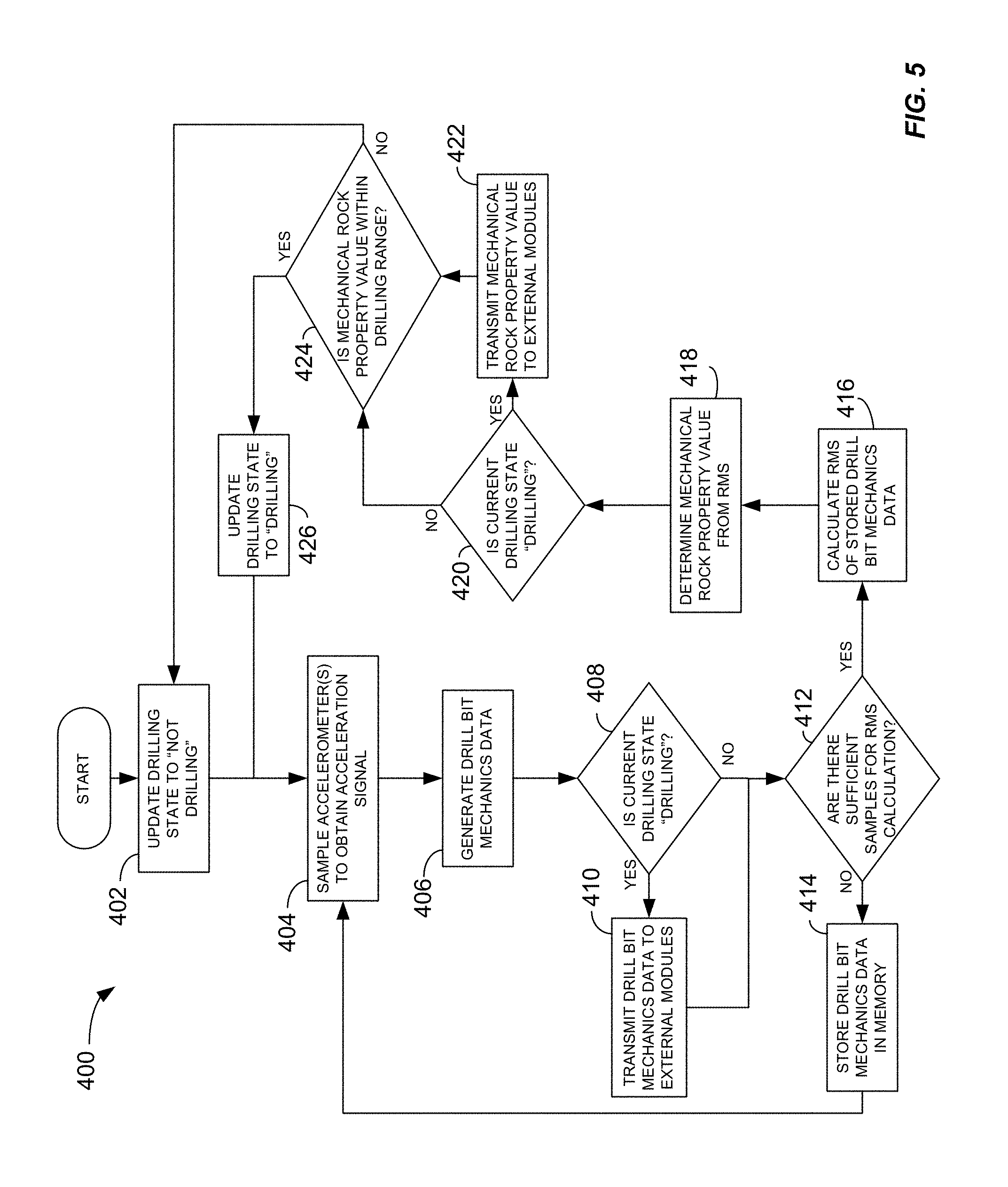
[0023] FIG. 5 is a flow chart illustrating a method for controlling a drilling measurement system;
[0024] FIG. 6 is a first example data output of the drilling measurement system of FIG. 3;
[0025] FIG. 7 is a flow chart illustrating a method of controlling a drilling system in response to characteristics of a subterranean formation identified using drill bit mechanics;
[0026] FIG. 8 is a graphical representation of biases that may be encountered during drilling of a subterranean formation and corresponding directional offsets that may be applied by systems in accordance with this disclosure to account for such biases; and
[0027] FIG. 9 is a schematic diagram of a computing module that may be used to implement functions disclosed herein.
DETAILED DESCRIPTION
[0028] Aspects of the present disclosure are directed to systems and methods for controlling drilling systems and drilling system behavior in relation to operations of drilling measurement systems during drilling operations. More specifically, aspects of the present disclosure systems and methods are directed to selectively controlling activation of components and functions of a drilling measurement system by monitoring mechanics of a drill bit during a drilling operation. The drill bit mechanics are analyzed to determine, among other things, one or more of whether the drill bit is actively engaged with a subterranean formation, whether the subterranean formation is conducive to hydraulic fracture treatment stimulation operations and whether the formation is favorable to undertake a steering or directional drilling operation.
[0029] In response to determining the drill bit is actively engaged with the subterranean formation, the drilling measurement system may enter a first mode in which certain functionalities and/or components of the drilling measurement are activated. Such functions may include, but are not limited to, data processing, data storage, and data transmission. In contrast, in response to determining the drill bit is disengaged from the subterranean formation, the drilling measurement system may enter a second mode in which functionalities and/or components of the drilling measurement system are deactivated. By selectively activating and deactivating components based on engagement of the drill bit with the subterranean formation, resources of the drilling measurement system, such as processing power, battery life, and onboard memory, may be conserved for times corresponding to active drilling. Moreover, by collecting data only during active drilling the drilling measurement system reduces the amount of irrelevant data collected during the drilling operation.
[0030] In response to determining whether the drill bit is actively engaged with a subterranean formation conducive to hydraulic fracture stimulation treatment operations the drilling measurement system may enter into a mode in which certain functionalities, components, and/or behaviors of the drilling system are activated or deactivated. Functions of the drilling system may include, but are not limited to, changing from a rotational drilling mode to a slide drilling mode or changing from a slide drilling mode to a rotational drilling mode. Further, based on the rock properties, one or more operational parameters of the drilling system to control the drilling system and modify the drilling system behavior. For example, in one implementation, the drilling system may be controlled in response to the rock property information to orient the bit based on whether the subterranean formation is likely to hold, build, drop, turn, or otherwise be subjected to a bias based on the mechanical properties of the formation through which the bit is drilling. Orienting the bit in such a manner may include, for example, operating the drilling system in a slide rotational drilling mode while maintaining a bent sub (and as a result the drill bit) at an angular orientation to offset the build, drop, turn, or other deviation that may occur as a result of the rock properties of the formation. Other examples of control of the drilling system and corresponding modifications to the drilling system behavior are discussed further in later portions of this disclosure.
[0031] Many modern wells are drilled and completed without obtaining adequate data regarding the heterogeneity of the subterranean formations through which the wells extend. Although systems to determine and log formation properties during drilling are available, such equipment is often expensive to procure and operate.
[0032] One significant cost associated with such systems is related to power supply and management. Measurement-while-drilling (MWD) and logging-while-drilling (LWD) systems are generally powered using one of a cable coupled to a surface power source and an onboard battery system. Regarding cable-based systems, significant costs are associated with purchasing and managing the necessary cabling, the various pieces of ancillary equipment required to generate and transmit power over the substantial distances that may exists between the measurement system and the surface power system, and the power losses caused by the overall resistance of the cables during transmission. Battery-based systems, on the other hand, can become depleted during drilling operations, thereby requiring multiple, costly drill string runs to sustain meaningful levels of formation data collection during drilling of a given wellbore. Power issues associated with MWD and LWD systems are further compounded by the fact that conventional MWD and LWD systems generally consume significant amounts of power when operational and lack mechanisms for intelligently energizing and de-energizing components of the MWD or LWD system. As a result, conventional LWD and MWD systems often inefficiently consume power by collecting and processing unnecessary data during periods in which no actual drilling is occurring, such as during connection of segments of drill pipe.
[0033] In light of the foregoing, among other things, the present disclosure is directed to systems and methods for controlling a drilling measurement system, such as by selectively energizing and deenergizing components of the drilling measurement system, based on a drilling state. More specifically, the systems and methods include receiving and processing signals from sensors, such as accelerometers, disposed near a drill bit of a drill string and configured to measure mechanics of the drill bit. Based on the signals, the drilling measurement system determines a drilling state corresponding to whether the drill is actively engaged with or disengaged from a subterranean formation. In certain implementations, additional measurements and signals, such as but not limited to one or more of weight-on-bit, rate-of-penetration, or differential pressure measurements, may be collected and further used in determining the drilling state. Depending on the drilling state, the drilling measurement system operates in one or more modes in which functions of the drilling measurement system and power-consuming components for performing such functions are enabled or disabled, accordingly. Such functions include, without limitation, writing drilling data to onboard memory of the drilling measurement system, transmitting drilling data to a remote receiver (such as by mud pulse telemetry), and performing high-speed digital signal processing using a dedicated digital signal processor of the drilling measurement system.
[0034] The present disclosure is further directed to systems and methods that receive and process signals from sensors, such as accelerometers, disposed near a drill bit of a drill string and configured to measure mechanics of the drill bit. Based on the signals, the drilling measurement system determines characteristics of the subterranean formation including, without limitation, the presence of fractures or other features within the subterranean formation and properties of the formation, such as a susceptibility to hydraulic fracturing operations. The characteristics of the formation may then be used to control the drilling system and modify the drilling system behavior. Such modifications may include, without limitation, changing one or more of drilling mode (e.g., between a slide drilling mode and a rotational drilling mode, which are described below), a rate of rotation of the drill bit and/or drill string, a rate of penetration, and a direction of drilling. In one example implementation, the mechanical rock properties may indicate that the subterranean formation is likely to cause the drill bit to build, drop, turn, or otherwise deviate from a predetermined trajectory. In response, the drilling system may automatically enter a slide drilling mode with the drill bit oriented at an angle that compensates for the deviation induced by the subterranean formation. Alternatively, the drilling system may operate in a rotational drilling mode but modify the power provided by the mud motor and/or the top drive to account for the undesirable deviation. In another example, the drilling system may automatically track or otherwise follow a path based on a feature of the subterranean formation identified from the mechanical rock property data. For example, the drilling system may cause a bit to follow a path within a predetermined distance range from the feature or maintain the bit at a particular orientation (e.g., perpendicular) relative to the feature. In yet another example, identification of a feature within the subterranean formation or portions of the subterranean formation having particular properties may cause drilling operations to cease and for the drilling system to generate and transmit alert messages to relevant personnel.
[0035] The term "drill bit mechanics" is used herein to generally describe the behavior of the drill bit during drilling operations. Accordingly, the term drill bit mechanics is intended to encompass both the kinematics and dynamics of the drill bit including, without limitation, the position, velocity, and acceleration of the drill bit; the orientation and changes in the orientation of the drill bit; forces generated by and acting upon the drill bit. Drill bit mechanics may be a result of one or both of the physical characteristics of the drill bit and interaction of the drill bit with a subterranean formation. With respect to interaction of the drill bit with a subterranean formation, drill bit mechanics may result from deformation or failure of rock within the subterranean formation.
[0036] The term "drilling system" is used to designate the equipment used to drill a well and includes a drill bit that breaks the rock by generating forces that are sufficient to overcome the strength of the rock either through mechanical or a combination of mechanical and hydraulic energy. The forces at the bit are generated either from the surface through a drive string or downhole through a motor. The drilling system uses fluids to power the motor and further to circulate the cuttings from the breakage of the rock to the surface. The drilling fluids also act to cool the bit and to provide pressure to stabilize to the walls of the borehole from collapse.
[0037] The term "drilling system behavior" is used to describe actions of the drilling system that occur during a drilling operation. Accordingly, control of the drilling system generally includes modifying or maintaining one or more drilling system behaviors by modifying or maintaining various operational parameters of the drilling system. One action of particular importance is the steering of the bit. In some instances, the drilling system may be engaging the bit with the formation through a combination of forces generated by the downhole motor and a top drive used to rotate the drill string. This is generally referred to as rotational drilling. Alternatively, the driller may choose not to rotate the string and opt to provide energy to the drill bit through the downhole motor only. This is referred to as slide drilling. In certain implementations, slide drilling may be used to control the direction of the well. For example, in order to steer or orient the direction of drilling during a slide, the bottom hole assembly may be fitted with a specialized sub, commonly referred to as a "bent sub". The bent sub generally includes a bend at a small angle offset from the axis of the drill string and a measurement device to determine the direction of the offset. As a result, a driller may rotate the drill string to point the drill bit and operate the drilling system in a sliding mode (e.g., with the mud motor activated but without rotation applied by the top drive) to drill in the direction in which the bit points. Accordingly, by controlling the amount of hole drilled in the sliding versus the rotating mode and the direction of the drill bit when drilling in the sliding mode, the wellbore trajectory can be controlled precisely.
[0038] In one particular implementation, the system may orient the bit to drill in a certain direction with respect to the orientations of the natural fracture systems within a subterranean formation. Alternatively or additionally, orientation may be made based on whether the rock properties and rock property relationships of the formation are likely to impart a bias on the drill bit during drilling that cause a hold, build, drop, turn, or other change in the direction of the bit, and, in particular, to counteract or offset such effects on the bit. Additionally or independently, the system may refer to mechanical rock property data for the target interval of interest and adjacent layers of the formation (e.g., above and/or below), and automatically orient the bit or change between sliding and rotating modes to maintain positioning within the formation of interest using rock properties of the adjacent layers as thresholding information.
[0039] The term "drilling measurement system" is used herein to encompass any system that collects data during a drilling operation. As a result, drilling measurement systems include, but are not limited to, MWD and LWD systems. Notably, drilling measurement systems described herein collect and process data corresponding to both drill string/drill bit dynamics and subterranean rock formation data and, as a result, combine at least a portion of the data collection functionality included in MWD and LWD systems, respectively.
[0040] Also, for purposes of this disclosure the term "mechanical rock property" or "rock property" is used generally used to describe physical properties of rock within a particular portion of the subterranean formation. Accordingly, the term is intended to include both specific properties (e.g., Poisson's ratio or Young's modulus of elasticity) for a particular portion of rock and properties of relationships between different portions of rock within the subterranean formation.
[0041] Implementations of the present disclosure include an acquisition module or board. The acquisition module is generally a microprocessor-based device in connection with a sensor array that performs various digital signal processing operations on signals received from the sensor array. In certain implementations, the acquisition module determines mechanical rock property values based on the signals and, based on the mechanical rock property values, determines whether active drilling is currently underway. For example, the acquisition module determines mechanical rock property values and compares those values to one or more predetermined ranges of values corresponding to different types of rock and subterranean formations. If the mechanical property values fall within one of the predetermined ranges of values, the acquisition module determines the drill bit is actively engaged with the subterranean formation. In response, the drilling measurement system selectively activates components configured to perform functions including, without limitation, storing, transmitting, and processing the sensor signals and/or data derived therefrom. If, on the other hand, the acquisition module determines the drill bit is disengaged from the subterranean formation (e.g., by determining the mechanical property value falls outside the one or more predetermined ranges), the drilling measurement system selectively deactivates the components, thereby conserving power. Data derived from the sensor signals, such as the mechanical rock property values, may be stored on board the drilling measurement system to facilitate additional computations and analysis, such as those that may be used to further control the drilling measurement system. The drilling measurement system may also be configured to upload or otherwise transmit the data to a remote receiver. In certain implementations, such transmission occurs in real-time during active drilling. Alternatively, the drilling measurement system may upload bulk data at a later time, for example, according to a predetermined uploading schedule, in response to a request received from the remote receiver, and the like.
[0042] If, on the other hand, the acquisition module determines the drill bit is disengaged from the subterranean formation (e.g., by determining mechanical property values fall outside the one or more predetermined ranges, that the formation mechanical rock properties indicate that the formation does not contain natural fractures, or the orientation of the well with respect to the orientation of the natural fractures is not conducive to hydraulic fracture stimulation treatments), the drilling measurement system selectively adjusts the drilling state variables to deactivate the rotating components, thereby conserving power, and steering the drill using just the motor. The steering of the motor may be based on the rock properties and rock property relationships and may continue until the rock properties again fall within ranges indicating a subterranean formation conducive to hydraulic fracture stimulation treatment operations. In both instances the drilling measurement system may change the mode of acquisition to accommodate the change in the drilling behavior accordingly.
[0043] In certain implementations, the acquisition module may use the mechanical property values to identify characteristics of the subterranean formation. Such characteristics may include features of the formation, such as fractures (e.g., natural fractures or fractures resulting from treatment of other nearby wells), or properties of the subterranean formation. In one example, the characteristics may include a relative susceptibility of the subterranean formation to fracturing operations. In response to the characteristics identified based on the mechanical property values, components of the drilling system may be selectively activated/deactivated or otherwise controlled to modify a behavior of the drilling system. For example, the drilling system may be switched between a slide drilling mode and a rotational drilling mode by deactivating or activating a top drive of the drilling system, respectively. Other examples of control of the drilling system based on the formation characteristics include, without limitation, one or more of changing a rotational speed of the drill bit or top drive, a direction of the drill bit, and a rate of penetration.
[0044] More generally, the characteristics of the subterranean formation may be used to determine the location, presence, or nature of features (such as boundaries, fractures, or other discontinuities) within the subterranean formation that may be used to control drilling operations and/or properties of the subterranean formation. In certain implementations, the identification or detection of certain features or properties of the subterranean formation may be used as a triggering event by the drilling system. In such implementations, one or more operational parameters of the drilling system may be automatically changed in response to detecting the characteristics. In other implementations, the characteristics of the subterranean formation may be used as a means of continuous feedback for the drilling system. For example, the mechanical rock properties may be used to infer an approximate distance from a boundary or other feature within the formation that is undesirable to cross. The drilling system may then control a drilling mode, rate, direction, etc., to maintain the drill bit at a predetermined distance (or within a predetermined range) from the boundary to avoid crossing the boundary.
[0045] Certain drill bit mechanics, such as vibrations, may attenuate rapidly and may generally have high frequency and low amplitude. Such mechanics may be best recorded as near to the drill bit as possible. Accordingly, in certain implementations, the acquisition module is included in a bit-sub, which is a short length of drill collar or similar tubular that can be used to mount the acquisition module behind the drill bit to facilitate data acquisition. Conventional measurement systems are generally deployed as part of a bottom hole assembly (BHA) when drilling a lateral or vertical well to send near-bit data and information to surface receivers in real-time. However, there is limited space for tools available in a near-bit environment. Colloquially, this is referred to as "first class" in the parlance of the BHA. Moreover, it is desirable to minimize the "bit-to-bend distance" especially when geo-steering lateral wells. As such, in practice, the length of the bit sub limits the space available for electronics and batteries and subsequently the power available to process and transmit the data. As a result, measurement systems in accordance with this disclose may generally be more compact and efficient than conventional systems, thereby reducing bit sub lengths and facilitating reduction in bit-to-bend distances.
[0046] In certain implementations, when the acquisition module determines drilling is occurring, real-time mechanical rock property information is obtained from the acquisition module using a radio frequency transmission system to "short hop" the mechanical rock property data to a mud pulser or similar transmission system for transmission of the mechanical rock property data to a remote receiver, such as a surface receiver. As a result, the short hop generally requires sufficient resources to power a signal over the length of a mud motor. In implementations including a mud pulser, the mud pulser is a more powerful transmission system than the short hop system disposed higher up in the BHA. The mud pulser generally includes sufficient resources to transmit binary encoded records of mechanical rock properties or other data to a surface receiver/acquisition system. The surface receiver detects and decodes the binary signal and extracts the data within the binary signal. The data is then stored, displayed, or otherwise made accessible using a computer in communication with the receiver system.
[0047] Other mechanisms to transfer data from a near-bit environment across a motor to the mud pulser may include a wired motor. In such applications, electrical impulses may be carried across the motor by the circuitry and connections of the motor between the below-motor, near-bit acquisition system, and the above-motor mud pulser.
[0048] One advantage of systems and methods of the present disclosure is the ability to differentiate drilling times from non-drilling times. When using a fast mud motor, for example, the rate of penetration (ROP) can proceed at rates as high as 330 feet per hour in some formations and basins. For these high-ROP wells, the time taken to make a connection between drill string sections can be a significant amount of rig time. That is, less time is taken to drill through the formation than preparing to drill. By obtaining drill bit mechanics signals and/or mechanical rock property values derived from such signals, it is possible to identify periods of time when the drill bit is actively engaged with a subterranean formation and is extending the wellbore. At other times, when the drill bit is disengaged from the subterranean formation, battery power, memory storage, processing power, and the like can be conserved by formulating and sending instructions to de-energize or deactivate components of the drilling measurement system for performing such functions.
[0049] Another advantage of systems and methods of the present disclosure is the ability to identify characteristics of a subterranean formation, such as susceptibility to hydraulic fracture stimulation treatment operations or particular features within the subterranean formation, and to rapidly control drilling operations in response. When using a fast mud motor, for example, the rate of penetration (ROP) can proceed at rates as high as 330 feet per hour in some formations and basins. For these high-ROP wells, the time taken to adjust the trajectory of the well by changing from rotational drilling to slide drilling or vice versa can be a significant amount of rig time. By obtaining drill bit mechanics signals and/or mechanical rock property values derived from such signals, it is possible to identify periods of time when the drill bit is within or adjacent portions of the subterranean formation having certain characteristics and to control the drilling system accordingly. For example, such data may be used to control the drill bit (e.g., by controlling a drilling mode or direction) such that the drill bit is maintained within a particular interval of the subterranean formation, in a certain direction relative to a feature of the subterranean formation (e.g., perpendicular to a natural fracture), within a predetermined range of distances from a feature, and the like.
[0050] The characteristics may also be used to control other operations, of the drilling system including, without limitation, activating, deactivating, or modifying operational parameters of other components of the drilling system. For example, and without limitation, characteristics of the subterranean formation may be used to activate, deactivate, or modify parameters of a data acquisition module in response to characteristics of the subterranean formation. For example, the data acquisition may be automatically activated or operated at a relatively higher resolution when in the presence of certain features of the subterranean formation but may be deactivated or operated at a relatively lower resolution in the absence of those same features.
[0051] As previously noted, implementations of methods and systems according to this disclosure include the derivation of mechanical rock property values from drill bit sensor signals corresponding to drill bit mechanics and associated data derived from such signals. Methods and apparatuses for performing such analysis, as well as details regarding the mechanics of drill bits during drilling operations, are provided in more detail in U.S. patent application Ser. No. 14/850,710, filed Sep. 10, 2015 and titled "Apparatus and Method Using Measurements Taken while Drilling to Map Mechanical Boundaries and Mechanical Rock Properties Along a Borehole" and U.S. patent application Ser. No. 15/182,012, filed Jun. 14, 2016, also titled "Apparatus and Method Using Measurements Taken while Drilling to Map Mechanical Boundaries and Mechanical Rock Properties Along a Borehole," both of which are hereby incorporated by reference in their entirety.
[0052] FIG. 1 is a schematic illustration of a drilling environment 100 including a surface 102, a subterranean formation 104, and a wellbore 105 including a vertical wellbore section 106 and a horizontal wellbore section 108. The drilling environment 100 depicts the drilling of the horizontal wellbore section 108 using a bottom hole assembly (BHA) 110 coupled to a drill string 112. The BHA 110 includes a drill bit 114, a mud motor 116, a bit sub 118 including various measurement components positioned between the drill bit 114 and the mud motor 116, and sections of drill pipe 120, 150 within the horizontal wellbore section 108.
[0053] Systems and methods in accordance with this disclosure determine a drilling state of the drill bit 114 and, more specifically, whether the drill bit 114 is engaged with or disengaged from the subterranean formation 104 based on mechanics of the drill bit 114. The signals used to determine the drilling state may be recorded as close to the drill bit 114 as practical to avoid attenuation through the BHA 110. Accordingly, one possible location for recording mechanics of the drill bit 114 is in the bit sub 118, which is disposed directly behind the drill bit 114 and ahead of the mud motor 116. The drill string 112 shown in FIG. 1 includes one bit sub, namely bit sub 118. However, in other implementations, multiple bit subs may be used along the drill string 112 for additional processing or transmission of the desired signal.
[0054] Drilling a wellbore generally involves using a portion of the weight of the drill string 112, known as weight-on-bit (WOB), to push the drill bit 114 into the subterranean formation 104. In addition to the WOB, a rotating force, known as torque-on-bit (TOB) is also applied to the drill bit 114. In certain drilling operations, TOB is generated by rotating the drill string 112 using a motor-driven turntable, or similar rotary device, located at the surface 102. In other drilling operations, such as that depicted in FIG. 1, TOB is generated by the mud motor 116. During drilling, drilling mud is pumped down the drill string 112 until it encounters the mud motor 116 and, more specifically, a power drive section (not shown) of the mud motor 116. The power drive section of the mud motor 116, which is mechanically coupled to the drill bit 114, converts a portion of the mud pressure and flow into a rotational force, thereby applying rotational torque on the drill bit 114.
[0055] The objective of the drilling process is to break rock of the subterranean formation 104 into fragments that are small enough they can be lifted and evacuated from the wellbore 105 with drilling fluids. Doing so accommodates the forward motion of the drill bit 114. It should be noted that the action of the drill bit 114 on the subterranean formation 104 fractures the subterranean formation 104 along the wellbore 105 and also in a region of the subterranean formation 104 immediately adjacent the wellbore 105. During drilling, the drill bit 114 may encounter existing fractures, such as fracture 122.
[0056] In FIG. 1 the bit sub 118 is shown between the drill bit 114 and the mud motor 116. More specifically, the bit sub 118 is operably coupled between the drill bit 114 and the mud motor 116 such that the mud motor 116 turns the drill bit 114 when mud is supplied to the mud motor 116 through drill string 112. The bit sub 118 provides a housing, typically in a cylindrical shape, or similar component to support various possible measurement components 124. Such measurement components include, without limitation, strain gauges, accelerometers, pressure sensors (which may measure the pressure of the mud flow), temperature sensors (which may measure the circulating temperature of the mud or other temperatures and which may be used to provide correction or offset of measurements or calculations that vary with temperature), gyroscopes (which may be used to measure inclination and/or directional changes of the drill bit 114 and the drill string 112), and other components to measure or derive data discussed herein. In one example, as shown in FIG. 1, strain gauges 128 are mounted on the bit sub 118 to determine WOB and TOB of the drill bit 114 (i.e., the force pushing the drill bit 114 and the force turning the drill bit 114 into the rock formation). Various possible ways of mounting the strain gauges, or combinations of strain gauges, are possible.
[0057] Additionally, as shown in FIG. 2, which is a representative front view of the drill bit 114, one or more accelerometers, such as accelerometer 126, may be placed to measure axial, rotary, and/or lateral acceleration of the drill bit 114. More specifically, the one or more accelerometers generate signals corresponding to the axial, rotary, and/or lateral acceleration of the drill bit 114 and transmit the signals to signal and data processing components disposed within the bit sub 118. Notably, the axis of rotation of the drill bit 114 is generally in center of the drill bit 114, but axial acceleration may be measured somewhat offset from the axis depending on the placement of the accelerometer 126.
[0058] As described below in more detail, the bit sub 118 or other such component, may house a drilling measurement system configured to process the signals received from the sensors, to determine mechanical rock property values based on the signals, to determine a drilling state based on the mechanical rock property values, and to transmit drilling data corresponding to one of the vibration signals and the mechanical rock property values to a remote receiver. In FIG. 1, for example, the bit sub 118 includes a "short hop" transmitter 128 that wirelessly transmits drilling data to a mud pulser 130 of the BHA 110 which then transmits the drilling data to a surface receiver 132 using mud pulse telemetry. Other systems such as a wired motor may be used to transmit data from the below-motor acquisition system to the above-motor mud pulser. Mud pulse telemetry is only an example method for transmitting the drilling data to the surface receiver 132. Other telemetry systems, such as wireline systems, wireless communication systems, and the like, may also be used to communicate the drilling data to the surface receiver 132.
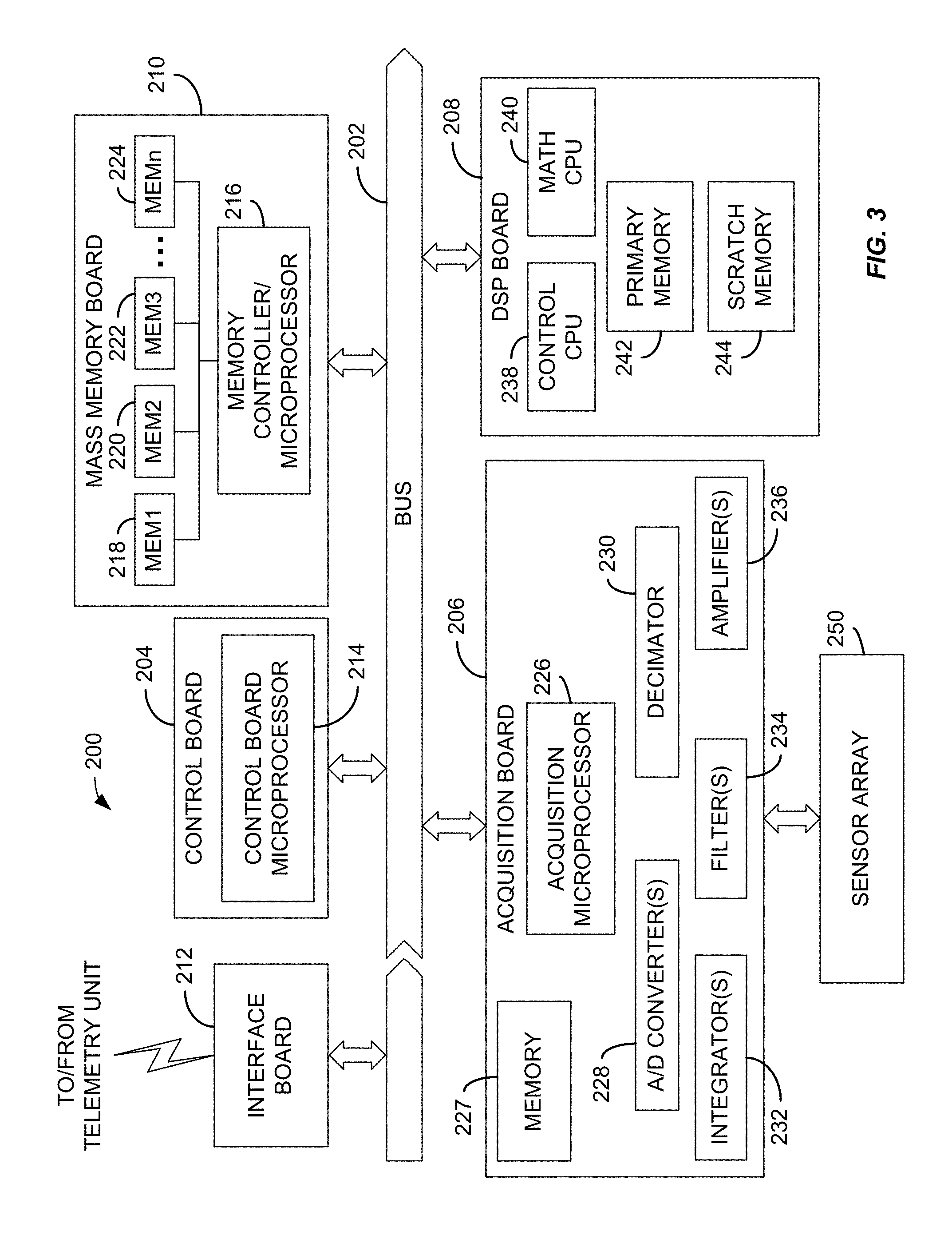
[0059] FIG. 3 is a schematic illustration of a drilling measurement system 200, such as may be contained, at least in part, within the bit sub 118 shown in FIG. 1. Generally, the drilling measurement system 200 is configured to receive signals from a sensor array and to process the signals to determine one or more mechanical rock property values. The drilling measurement system 200 may be further configured to at least one of transmit to a remote receiver (such as the remote receiver 132 of FIG. 1) and store drilling data corresponding to the signals and/or the mechanical property values.
[0060] The drilling measurement system 200 generally includes a plurality of modules configured to perform various functions of the drilling measurement system 200. In FIG. 3, for example, each module is represented as a separate circuit board coupled to a central bus 202 that facilitates communication between the different modules/boards. The modules/circuit boards included in the drilling measurement system 200 include a control board 204, a data acquisition board 206, a digital signal processing (DSP) board 208, a mass memory board 210, and an interface board 212. Although illustrated as physically separate boards, which each may include a printed circuit board with various hardware elements mounted and interconnected thereon, any or all of the control board 204, the data acquisition board 206, the digital signal processing (DSP) board 208, the mass memory board 210, and the interface board 212 may be integrated into a single board or otherwise provided in any number of boards. Moreover, functions of the various modules/boards of the drilling measurement system 200 may be performed using dedicated hardware or software. For example, the drilling measurement system 200 may include one or more application-specific integrated circuits (ASICs) or similar custom integrated circuits that are programmed to perform the various functions described herein.
[0061] The control board 204 includes a control board microprocessor 214. The control board microprocessor 214 is communicatively coupled to the bus 202 and facilitates communication between the various components of the drilling measurement system 200. In certain implementations, the control board microprocessor 214 is configured to selectively activate or deactivate functions of other boards, such as the DSP board 208, the mass memory board 210, and the interface board 212, based on a drilling state. For example, the control board microprocessor 214 may selectively energize one or more the boards 208-212 or components of the one or more boards. In other implementations, the control board 214 selectively changes one or more boards or components thereof between a low-power state, such as a "sleep" state, and an active state.
[0062] The data acquisition board 206 includes an acquisition microprocessor 226 that receives signals from a sensor array 250 communicatively coupled to the data acquisition board 206. The data acquisition board 206 generally includes components and/or software for processing signals received from the sensor array 250 to generate drill bit mechanics data and mechanical rock property values based on the drill bit mechanics data. Processing of the signals received from the sensors to generate drill bit mechanics data may include, without limitation, (i) amplifying the signals using one or more amplifiers 236; (ii) integrating the vibration signals using one or more integrators 232; (iii) filtering the vibration signals using one or more filters 234; (iv) converting the signals to a digital form using an analog-to-digital converter 228; and (v) down-sampling or decimating a digital form of the signals using a decimator 230. The data acquisition board 206 may further include (or otherwise have access to) a memory 227 that stores computer executable instructions for execution by the acquisition microprocessor 226 to perform or coordinate performance of the various processing functions of the acquisition board 206.
[0063] In certain implementations, the acquisition microprocessor 226 executes instructions to determine mechanical rock property values based on the drill bit mechanics data. The process of determining mechanical rock properties based on drill bit mechanics data is provided in detail in U.S. patent application Ser. Nos. 14/850,710 and 15/182,012, both of which are titled "Apparatus and Method Using Measurements Taken while Drilling to Map Mechanical Boundaries and Mechanical Rock Properties Along a Borehole," however, a summary of the process is provided below.
[0064] In one implementation, mechanical rock properties are determined by deriving stress-strain relationships by systematically relating forces acting on the formation. The forces acting on the formation are generally ascertained from the drill bit mechanics measured during the cutting action of the bit. This approach allows elastic coefficients (K) to be derived in accordance with the following equation:
S=K e
where (e) is the general deformation (strain) of a rock formation in response to the forces acting on a rock formation (S) (stress).
[0065] Strain can generally be derived from motion of the drill bit. For example, one or more accelerometers may be disposed near the drill bit to provide acceleration signals in response to vibrations of the drill bit during active drilling. Integration of the acceleration signals can then be applied to determine the corresponding velocity and position of the drill bit and, as a result, the strain behavior of the formation. Stress, on the other hand, is generally derived from forces acting on the bit. For example, in various implementations, stress may be determined from any of (i) downhole measurements of torque and/or weight on bit; (ii) surface measurements of torque and/or weight on bit; or (iii) the accelerations of the drill bit as the acceleration is a representation of force per unit mass. Such forces can be converted to stresses with knowledge of the effective contact area of the drill bit and formation and the effective rock volume the drill bit is acting on. Conversely, forces can be substituted for stresses with the understanding that a geometric correction in relation to the effective contact area is required to obtain absolute values for the mechanical rock properties. One example of such a contact area is the area of the drill bit.
[0066] Equations of linear elasticity are useful for describing the relationship between the changes in shape and position of a material in relation to the forces acting on the material. Such stress-strain relationships are known in general as Hooke's law where the coupling of the stress-strain relationship behavior is described through a matrix of coefficients whose values depend on the conditions used to load the material in relation to the structural symmetry of the material being loaded. These coefficients (colloquially known as the cij's) can be arranged in well-known and convenient forms to represent various mechanical properties including, without limitation, Young's Modulus of Elasticity (YME) and Poisson's Ratio (PR).
[0067] In one specific implementation, linear elasticity equations are uniquely expressed through the application and use of drill bit mechanics data to (i) populate the variables of the constitutive equations of linear elasticity and (ii) undertake an analysis of the constitutive equations to obtain measurements of near-wellbore mechanical rock properties, such as YME and PR. Further, variations in the mechanical rock properties (e.g., YME and PR) are used to identify the nature and occurrence of mechanical boundaries or discontinuities in the subsurface such as fractures.
[0068] Techniques to determine near-wellbore mechanical rock properties from drill bit mechanics data may involve processing drill bit mechanics data including, without limitation, the weight on bit, torque on bit, annular fluid pressure, angular bit speed, and components of motion describing the acceleration of the drill bit, including axial and rotary or tangential accelerations to: (i) obtain sets of MWD data corresponding to known temporal and spatial positions along the borehole; (ii) calculate the forces acting on the rock formation in connection with the drilling apparatus and drilling fluids, (iii) calculate the displacements of the drill bit as it is accommodated by the deformation of the rock formation; (iv) inform the terms and loading conditions (variables) of a linear, elastic stress-strain relationship that describes the constitutive behavior of the rock formation in relation to the orientation of the well; (v) calculate mechanical rock properties using the constitutive linear elastic equations as determined through the application and use of the drill bit mechanics data; and (vi) analyze the mechanical rock properties with respect to the axis of material symmetry in relation to the orientation of the well to identify the nature and occurrence of mechanical boundaries and discontinuities such as fractures and bedding planes among other things.
[0069] Typical values for mechanical rock properties and mechanical rock property relationships have been well established and are well known with respect to various formations typically encountered when drilling. The values of YME typically range between 1-20 Mpsi and PR typically falls between 0.1 and 0.45. By systematically comparing the rock properties obtained using systems and methods in accordance with this disclosure to typical values or ranges of values expected for a given formation, it is possible to determine when the bit is interacting or otherwise engaged with the formation. By systematically comparing the mechanical rock properties with respect to the axis of material symmetry in relation to the orientation of the well it is possible to predict the nature and occurrence of mechanical boundaries and discontinuities such as fractures and bedding planes in the formation, among other things.
[0070] In certain implementations, after determining the mechanical rock property values corresponding to the drill bit mechanics data, the acquisition microprocessor 214 determines whether the calculated mechanical rock property values indicate that the drill bit is actively engaged with or disengaged from a subterranean formation. For example, in certain implementations the acquisition microprocessor 214 calculates values corresponding to mechanical rock properties, such as Poisson's ratio (PR) and Young's modulus of elasticity (YME), and compares the calculated values to one or more predetermined ranges of the mechanical rock properties corresponding to known subterranean formations. If the calculated value falls within one of the one or more predetermined ranges, it is likely that the drill bit is actively engaged with the subterranean formation. Alternatively, if the calculated value falls outside of each of the one or more predetermined ranges, it is likely that the drill bit is disengaged from the subterranean formation.
[0071] In addition to determining whether the drill bit is engaged with or disengaged from the subterranean formation, the mechanical rock property values may be used to infer characteristics of the subterranean formation. The properties and characteristics may include, without limitation, one or more of the occurrence, location, and nature of features within the formation such as fractures, boundaries, and bedding planes. Such features may be naturally occurring within the formation or may be the result of other activity, such as drilling and fracturing activity, within the formation. For example, and without limitation, the mechanical rock properties may be used to identify fractures within the formation that may be the result of fracturing operations conducted on a nearby well.
[0072] The characteristics of the subterranean formation inferred from the mechanical rock property data may be used in various ways including, without limitation, monitoring the current drilling operations and controlling the drilling system to modify a drilling system behavior. For example, in one implementation, detecting a feature of the subterranean formation within the mechanical rock property data may be used to confirm the location of the drill bit within the formation, such as by cross-referencing the location of the feature with previously obtained seismic or similar geologic data. In another example implementation, the formation characteristics may be stored in addition to seismic or other geological data to supplement or verify the geological data.
[0073] In still other implementations, drilling operations may be controlled in various ways in response to the formation characteristics. Control of drilling operations may include, without limitation, one or more of changing a drilling mode (e.g., slide drilling or rotational drilling); altering a direction of the drill bit (such as by altering an orientation of a bent sub of the drilling system); altering a rotational speed of a drill bit or top drive; and increasing or decreasing a rate of penetration of the drill bit. In a first example implementation, the drilling operations may be controlled to maintain the drill bit at a predetermined distance or within a range of predetermined distances relative to a feature of the formation. So, for example, the drilling system may automatically modify one or more of an orientation of the drill bit, a rotational speed of the drill bit, a rotational speed of a top drive, or a drilling mode in response to detecting certain features of the formation. In another example implementation, the drilling operations may be controlled to maintain the drill bit at a predetermined orientation relative to a feature, such as maintaining the drill bit substantially perpendicular to a natural fracture within the formation.
[0074] In yet another example implementation, the drilling system may automatically adjust one or more drilling parameters to reduce deviation from a predetermined drilling trajectory that may result from a bias induced on the drill bit during drilling. More specifically, certain properties of the formation may cause the drill bit to hold, bend, drop, turn, or other otherwise deviate from a predetermined trajectory due to the interaction of the drill bit with the rock face during drilling. Accordingly, based on the mechanical rock properties and corresponding characteristics of the formation, the drilling system may automatically adjust drilling parameters to offset or otherwise account for the bias caused by the formation. For example and without limitation, the drilling system may automatically adjust one or more of the orientation of a drill bit (e.g., by adjusting the orientation of a bent sub when in a slide drilling mode), a drilling mode (e.g., by changing between a slide drilling mode and a rotational drilling mode), the amount of weight-on-bit, a rotational speed of the mud motor or top drive, or any other operational parameter that may affect the drilling direction.
[0075] In the foregoing examples, the information regarding the formation is used as a means of continuous feedback for controlling the drilling system. In still other implementations, the information regarding the formation may be used as triggers for transitions between different phases of a drilling operation. For example, a drilling operation may proceed in a first direction and at a first rate until a certain feature of the formation (e.g., a fracture) is detected. Following detection of the feature, the drilling operation may continue in a second direction at a second rate. Similarly, detection of a certain feature or characteristics of the formation based on the mechanical rock property data may be used to trigger a stoppage or shutdown of drilling operations. So, for example, if the mechanical rock property data indicates the presence of a fracture or discontinuity in close proximity, the drilling operations may be automatically stopped to avoid breaching the feature.
[0076] In certain implementations, the information regarding the formation and, more specifically, the characteristics of the formation may also be used to trigger the generation and transmission of one or more messages. Such messages may be used, for example, to inform personnel regarding the detection of features of characteristics of the formation or the progress of the drilling operations and may be provided in various forms including, without limitation, one or more of text messages, email, prerecorded voice messages, and the like.
[0077] In certain implementations, the information regarding the subterranean formation inferred from the mechanical rock property data may also be used to modify, supplement, or classify the mechanical rock property data collected and/or transmitted by the drilling measurement system. For example, in certain implementations, the system may determine that a portion of the subterranean formation is particularly susceptible to hydraulic fracturing or similar treatment operations and classify the corresponding mechanical rock property data accordingly. Such classification may include, among other things, tagging the data with a corresponding identifier or maintaining a separate log including coordinates or other information for relevant portions of the subterranean formation.
[0078] After determining whether the drill bit is actively engaged with the subterranean formation and/or whether the drill bit is actively engaged with the subterranean formation that is conducive or otherwise susceptible to hydraulic fracture stimulation treatment operations, the acquisition microprocessor 214 may communicate the drilling state to the control board 204. In certain implementations, the acquisition microprocessor 214 transmits a message containing the current drilling state to the control board 204. In other implementations, a shared memory may be used to store a drilling state variable that is updateable by the acquisition microprocessor 214 and retrievable by the control board 204. Based on the drilling state, the control board 204 activates or deactivates functions of the other components of the drilling measurement system 200. More specifically, when the drilling state indicates the drill bit is actively engaged with the subterranean formation and/or that the drill bit is actively engaged with the subterranean formation that is conducive or otherwise susceptible to hydraulic fracture stimulation treatment operations, the control board 204 operates the drilling measurement system 200 in a first mode and when the drilling state indicates the drill bit is disengaged from the subterranean formation, the control board 204 operates the drilling measurement system 200 in a second mode. The second mode generally corresponds to a low power consumption mode in which one or more components or functions of the drilling measurement system 200 are deactivated. For example, the component or functions deactivated in the first mode may correspond to components or functions configured to perform processing, store data, or transmit data. Accordingly, the second mode corresponds to a mode in which the drilling measurement system 200 monitors signals from the accelerometer array 250 to identify when drilling has begun. In contrast, when operating in the first mode, one or more of the components or functions deactivated in the second mode are activated. For example, when operating in the first mode, the drilling measurement system 200 may be configured to perform at least one of additional signal processing, data storage, and data transmission using the DSP board 206, the mass memory board 210, and the interface board 212, respectively.
[0079] The data acquisition board 206 generally includes sufficient computing power and computing modules to perform processing of at least a portion of the signals received from the sensor array 250 or derived from the received signals by the acquisition board 206. In certain operational modes, however, additional processing power may be required to generate greater quantities of drilling data. Such processing power may be provided by the DSP board 208 or a similar data processing module. For example, in certain implementations, the DSP board 208 includes a DSP control microprocessor 238, a DSP math processor 240, and one or more memories, such as a DSP primary memory 242 and a DSP scratchpad memory 244. In such implementations, the DSP control microprocessor 238 provides control of the DSP board 208, including managing data flow into and out of the DSP math processor 240, by executing instructions stored in the DSP primary memory 242. The DSP math processor 240, on the other hand, is a high-speed math processor configured to transform time-domain vibration signals received from the accelerometer array 250 into the frequency domain, such as by performing a fast Fourier transform (FFT) on the received time-domain signals. Such an FFT performed by the DSP board 208 may transform n points (for example, n=1024 points) of time domain information into n/2 (n/2=512) points of frequency domain data, which include the amplitude and frequency components present in the originally received signals. To facilitate processing by the DSP math processor 240, the DSP math processor 240 may store calculations, data, and other work in the DSP scratchpad memory 244. In certain implementations, the various filtering functions described above as being performed on the acquisition board 226 may instead be performed by the DSP board 208.
[0080] During operation, the control board 204 may selectively activate and deactivate the DSP board 208 or components of the DSP board 208 based on the drilling state as determined by the data acquisition board 206. If the data acquisition board 206 determines that active drilling is underway, the control board 204 may energize the DSP board 208 or otherwise send a message to the DSP board 208 to begin transformation of time-domain data received from the acquisition board 206 into the frequency domain.
[0081] The mass memory board 210 stores drilling data received from the acquisition board 206. More specifically, the mass memory board 210 generally includes a memory microprocessor or microcontroller 216 and one or more memory modules 218-224. The memory microprocessor/microcontroller 216 generally performs memory management functions including, without limitation, reading, writing, and deleting data in the memory modules 218-224. In certain implementations, each of the memory modules 218-224 are dynamic random access memory (DRAM) modules or any other suitable type of memory for storing data associated with the signals received from the sensor array 250. Such data includes, without limitation, drill bit mechanics data generated by the acquisition board 206 from the sensor signals during active drilling and mechanical rock property data derived from the drill bit mechanics data. The mass memory board 210 may store the data for remote retrieval, such as by the remote receiver 132 of FIG. 1. For example, the mass memory board 210 may be configured to provide, in response to a data retrieval request, at least a portion of the drilling data stored in one or more of the memory module 218-224. In certain implementations, the memory board 210 is configured to deenergize or otherwise deactivate write functionality when the drill bit is disengaged from a subterranean formation, thereby conserving memory resources of the drilling measurement system 200.
[0082] The interface board 212 communicates data from the drilling measurement system 200 to one or more external devices. In certain implementations the interface board 212 is configured to communicate with a downhole telemetry device, such as a mud pulser in proximity to the drilling measurement system 200. For example, the interface board 212 may be directly wired to or communicate wirelessly with a mud pulser disposed on the BHA. In wireless implementations, the interface board 212 may be configured to transmit data to the mud pulser using a short hop wireless system. The mud pulser may then transmit the data from the interface board 212 to a remote receiver.
[0083] The sensor array 250 includes one or more sensors that generate electrical signals in response to motion of the drill bit and/or forces experienced by the drill bit. The sensor array 250 may include sensors of different types and configured to measure different behavior of the drill bit. Sensors of the sensor array 250 may include, but are not limited to, accelerometers, gyros, strain gauges, pressure switches, load cells, potentiometers, encoders, optical switches, tachometers, Hall effect sensors, and the like. In certain implementations, the sensor array 250 includes one or more single or multi-axis accelerometers each of which may produce signals over one or more channels. In certain implementations, accelerometers of the sensor array 250 are low-power accelerometers selected to have performance characteristics conducive to a drill bit vibration measurement application. For example, such performance characteristics may include, without limitation, having an accuracy of .+-.5% from 100 to 10000 Hz and .+-.3 dB up to 30 kHz, being able to operate at temperatures up to 150 degrees Celsius, and having a turn-on settling time of less than a few minutes. The accelerometers may also be selected to have particular bandwidths and dynamic ranges conducive to drill bit vibration monitoring. For example, in certain applications, accelerometers may be selected to have a bandwidth of 10-50000 Hz and dynamic ranges of +/-300 g's and +/-100 g's for measuring motion in the radial or tangential direction and axial direction, respectively. The accelerometers of the sensor array 250 may be arranged in a recording configuration to simultaneously measure the axial and lateral or tangential and radial or centripetal components of motion about the axis of drilling. The accelerometers of the sensor array 250 may also be placed in an orthogonal arrangement of channels sufficient to cancel linear motions of the drill bit using summations of the accelerometer signals.
[0084] During operation, the drilling measurement system 200 may collect drill bit mechanics data in various data collection modes. In general, the data collection modes are designed to accommodate a native sample rate for obtaining signals from the accelerometer array 250 that is above or equal to the rate at which such signals can be processed and stored by the other components of the drilling measurement system 200. To the extent the drilling measurement system 200 stores data, data storage may be at a predetermined resolution that provides meaningful differentiation. For example, in one implementation, the drilling measurement system 200 has a native sample rate of 50 kHz and is configured to process and store data at a minimum of 5 kHz at a resolution of no less than 16-bits. In certain implementations, the drilling measurement system 200 is configured to automatically enter one of the data collection modes after the occurrence of predetermined events, such as the drill bit reaching a specified depth or a particular amount of time elapsing, such as the time required to introduce the drilling measurement system 200 into a wellbore.
[0085] A first possible data collection mode, referred to herein as "native mode," involves continuous sampling and storage of signals from the accelerometer array 250 at the native sample rate and at full resolution until memory is full. As such, the native mode may be useful for testing and troubleshooting the drilling measurement system 200.
[0086] In a second possible data collection mode, referred to herein as "burst mode," the accelerometer array 250 is sampled and the corresponding data is stored at the native sample rate during discrete time windows that occur at regular intervals. For example, in one implementation, the accelerometer array 250 is sampled and the corresponding data is processed and stored at the native sample rate for an 8 second "burst" that occurs every 120 seconds. The length of the discrete time windows may vary depending on the native sample rate and the available memory. The burst mode may be appreciated in instances when accurate determination of formation properties requires a relatively high sampling rate but power available to the drilling measurement system 200 is sufficiently limited that continuous sampling at the high sampling rate would detrimentally impact overall drilling time. In certain implementations, the burst mode may be used to determine what bandwidth would be sufficient to retrieve information related to the accelerations of the bit and the motions of the bit that would be most representative of the mechanical rock properties. For example, the burst mode may be used with different settings (e.g., number of measurements per burst, time between measurements within a given burst, time between bursts) to identify the optimal settings for a given drilling application.
[0087] In a third possible data collection mode, referred to herein as "continuous mode," the accelerometer array 250 is continuously sampled at the native sample rate, but only a decimated or down-sampled form of the signals or corresponding data are stored. For example, in one implementation of continuous mode, 1 out of every 10 samples retrieved form the accelerometer array 250 is processed and stored. Notably, this mode allows post-processing of the stored data for discrete fracture detection. In certain implementations, the down-sampling rate may be based on data previously obtained during operation of the drilling measurement system 200 in burst mode. For example, an operator may perform a first drilling run in which the drilling measurement system 200 is operated in burst mode. The operator may then analyze the data collected during the first drilling run may be evaluated to determine the frequency of samples required to accurately assess the heterogeneity of the formation and its mechanical properties. A subsequent drilling run may then be performed using the drilling measurement system 200 in continuous mode with a down-sampling rate corresponding to the frequency determined from the first drilling run.
[0088] In a fourth possible data collection mode, referred to herein as "continuous-plus-burst mode," the drilling measurement system 200 alternates between the previously described continuous and burst modes at regular intervals. For example, the drilling measurement system 200 may generally process signals and store data corresponding to 1 out of every 10 samples, except for regular intervals of time in which the drilling measurement system 200 operates in burst mode. During the burst mode intervals, the drilling measurement system 200 samples and stores data at the native sample rate. An example time window and interval of the burst mode could be 10 seconds every 600 seconds. In other words, the drilling measurement system 200 would operate in continuous mode for 590 seconds and then would switch to burst mode for 10 seconds before returning to continuous mode. In certain implementations, the continuous-plus-burst mode is the standard operational mode for the drilling measurement system 200.
[0089] Any of the foregoing data collection modes benefit from operating only when the drill bit is engaged with a formation and/or engaged with a formation that is specifically conducive to hydraulic fracture stimulation treatment operations as determined by the data acquisition board 206. More specifically, by limiting power consumption and memory usage to periods corresponding to only active drilling or when the drilling mechanics indicates the presence of natural fractures, such resources may be more effectively used to capture a greater proportion of relevant drilling data and/or drilling data at a higher resolution. For example, when operating in burst mode, additional memory that would otherwise be used to store irrelevant (i.e., non-active) drilling data) may be used to accommodate longer burst durations and/or increased burst frequencies as compared to a drilling measurement system that does not differentiate between active and non-active drilling periods and, as a result, constantly collects data in burst mode. Similarly, when operating in continuous mode, the additional memory that would otherwise be used to store irrelevant drilling data may instead be used to decrease the rate of decimation (e.g., reducing decimation from 1 in 10 samples to 1 in 5 samples) as compared to a drilling measurement system that does not differentiate between active and non-active drilling periods. For example, when drilling through a reservoir that is naturally fractured, the ability to determine the nature and occurrences of natural fractures from the processing and analysis of the drilling dynamics data may benefit from a continuous mode of acquisition.
[0090] In addition to the collecting and storing data, the drilling measurement system 200 may also be configured to transmit drilling data to a remote receiver. For example, the drilling measurement system 200 may transmit data using a short hop communication system to a mud pulser or other telemetry unit that then transmits the data to a remote receiver. In certain implementations, the transmission of data to the remote received occurs in real-time. Alternatively, the drilling measurement system 200 may store data, such as in the memory board 210, and transmit the data to the remote server in batches at regular intervals or in response to receiving a request from the remote receiver.
[0091] The data transmitted from the drilling measurement system 200 to the remote receiver may correspond to a reduced set of the data generated by and/or stored by the drilling measurement system 200. Such reduced data sets may be useful for obtaining real-time data and feedback from the drilling measurement system 200 during a drilling operation. For example, the drilling measurement system 200 may sample the sensor array 250 at the native sample rate but only transmit (and also possibly store) a band-limited root mean square (RMS) average of the drill bit mechanics data corresponding to a specific time window or record of the data. The RMS or other attributes of the data could be further processed to obtain mechanical rock property values. The mechanical rock property measurements, or an average thereof over a particular period of time, may then be transmitted to the remote receiver. Similarly, the drilling measurement system 200 may be configured to retrieve data from the memory board 210, perform further processing on the retrieved data, and transmit the further processed data to the remote receiver. For example, in one implementation, the drilling measurement system 200 retrieves decimated/down-sampled data obtained during operation in the continuous mode and processes the data to obtain band-limited RMS measurements or mechanical rock property values corresponding to the retrieved data. The band-limited RMS measurements or mechanical rock property measurements may then be transmitted to the remote receiver.
[0092] FIG. 4 is a schematic illustration of a data acquisition board 300 that may be used in the drilling measurement system 200 of FIG. 3. The data acquisition board 300 includes an acquisition microprocessor 326 in communication with one or more components configured to receive and process signals from an accelerometer array, such as the sensor array 250 of FIG. 3. More specifically, the acquisition board 300 generally consists of digital selectable circuits to amplify, integrate, filter and otherwise process signals received from the sensor array 250.
[0093] To maintain low power consumption, the acquisition microprocessor 326 may utilize a relatively slow microprocessor, particularly as compared to the DSP math processor 240 of the DSP board 208 shown in FIG. 3. The data acquisition board 300 may include a read-only memory (ROM) 372, such as a PROM, for storing instructions executable by the acquisition microprocessor 326 and a random access memory (RAM) 374 for transitory storage of data used by the acquisition microprocessor 326 during execution of the instructions stored in the ROM 372. In general, the acquisition microprocessor 326 is configured to perform functions, such as obtaining RMS averages of digitized and filtered signals held in the RAM 374, and arithmetic functions such as multiplication, division, addition, and subtraction, including performing such arithmetic functions on the calculated RMS averages.
[0094] The data acquisition board 300 is communicatively coupled, such as by a bus, to a control board, such as the control board 204 of FIG. 3. During operation, the control board 204 communicates data and instructions to the acquisition microprocessor 326 such as a mode of operation and a time during which the data acquisition board 300 is to be acquiring data from the sensor array. The data and instructions from the control board 204 are generally used as inputs during execution of the instructions stored in the ROM 372 by the acquisition microprocessor 326. For example, the instructions stored in the ROM 372 may cause the acquisition microprocessor 326 to digitally control, without limitation, one or more of the rate at which the sensor array is sampled, the gain applied to signals received from the sensor array, the parameters of any filtration performed on signals received from the sensor array, and other parameters related to signal processing.
[0095] In one implementation, the data acquisition board 300 supplies excitation current to the sensors of the sensor array through a power supply 376 and determines the status of the sensors. To determine the status of the sensors, the data acquisition board 300 may first test for short and open circuits of each of the channels of the sensor array. For example, under control of the acquisition microprocessor 326 and prior to sampling, the acquisition board 300 may examine the DC component of signals from sensors of the sensor array. If the DC component of the signals is found to be too near the voltage of a supply rail, the circuit between the corresponding sensor and the acquisition board 300 may be deemed to be open. Conversely, if the DC component of a signal received from the sensor array is too near ground, the corresponding circuit may be considered shorted. If the sensor status test indicates either an open or short circuit condition exists, the acquisition board 300 may be configured to transmit a corresponding notification message or update a global sensor status variable in response. The control board 204 may then receive the message or retrieve the global variable identifying the abnormal state and proceed with remedial measures including, without limitation, activating or deactivating components of the drilling measurement system 200 and transmitting an alarm or similar message to an operator. Such an alarm or message may cause, without limitation, illumination of a light emitting diode, a color change of an icon or similar indicator of a system interface, generation of an audible alarm, and the like.
[0096] In certain implementations, the sensor array consists of one or more tri-axial mounted accelerometers where the axis of the accelerometers are oriented to (i) the drilling face, (ii) the axis of drilling, and (iii) the drilling collar. Accordingly, one component (the axial channel) is perpendicular to the drilling face, a second component (the lateral channel) is tangential to the drilling collar and perpendicular to the direction of drilling, and a third component (the radial channel) is oriented perpendicular to each of the drilling collar and the drilling face. Multiple pairs of accelerometers may be arranged in this configuration. In such implementations, the lateral and radial channels of accelerometers may be oriented perpendicular to each other, thereby forming an accelerometer "dipole." By doing so, the lateral and radial components of the accelerometers of the dipole may be summed, such as by a summer 352 to produce a measurement of the angular acceleration. In the implementation of FIG. 4, the summer 352 receives signals from the sensor array over multiple channels 382. The summer 352 then combines the channels 382 to produce two signals; the first signal (a) corresponding to the linear acceleration of the drill bit and the second signal (a) corresponding to the angular acceleration of the drill bit.
[0097] After summation of the sensor signals, the data acquisition board 300 may perform gain ranging on each received signal using one or more amplifiers 354. The amplifiers 354 amplify the signals received from the accelerometers, which may be in the range of a few millivolts, into higher voltage signals, which may span several volts. Doing so aids in attenuating noise components of the accelerometer signals and facilitates later processing of the accelerometer signals.
[0098] In certain applications, drill bit mechanics, such as drilling-induced vibrations, may be expected to have a wide dynamic range. To enhance the resolution of the data, automatic gain switching of the analog amplifiers may be used. In such implementations, the amplifiers 354 may be digitally controlled amplifiers under control of the acquisition microprocessor 326. During operation, the acquisition microprocessor 326 may adjust the gain applied by the amplifier 354 such that the highest suitable gain is applied to the incoming accelerometer signals. For example, at the beginning of each data collection, the amplifiers 354 are initially set to maximum gain and the incoming vibration signals are sampled. If the amplified signals equal or exceed a predetermined threshold, the amplifier gain may be reduced by a predetermined amount, for example, by use of a gain select bit operating switch to change the feedback impedance of the gain amplifier. In certain implementations, the corresponding gain setting is attached or otherwise associated with data generated from the amplified signals and stored with the data for future reference.
[0099] After amplification, each of the sensor signals may be passed through one or more integrators 356. For example, in implementations in which the sensor signals include acceleration signals received from one or more accelerometers, the accelerometer signals may be passed through a first integrator circuit, which converts the acceleration signals into velocity signals. The output of the first integrator circuit is then passed through a second integrator circuit, thereby converting the velocity signals into position signals. Such conversion may be performed for each incoming channel of the accelerometers of the sensor array. Accordingly, in implementations in which there are two input channels, one corresponding to angular acceleration and one corresponding to axial acceleration, a minimum of six signals may be generated using a two-integrator arrangement. Referring to the implementation of FIG. 4, the integrators 356 receive an axial acceleration signal (a) and an angular acceleration signal (a) as amplified by the amplifiers 354. The acceleration signals are then integrated using the integrators 356 to generate corresponding velocity and displacement signals. More specifically, the axial acceleration signal (a) is integrated to obtain an axial velocity or rate of penetration signal (ROP), which is then integrated to obtain an axial displacement signal (d). Similarly, the angular acceleration signal (.alpha.) is first integrated to obtain an angular velocity signal (.omega.), which is then integrated to obtain an angular displacement signal (.theta.).
[0100] Each of the axial signals (a, ROP, d) and the angular signals (.alpha., .omega., .theta.) may then be filtered using one or more filters. Filtering conditions the signals prior to digitization and limits the bandwidths over which data averaging calculations, such as calculations for obtaining a band-limited RMS measure of the signals, are obtained. In certain implementations, filtering may be conducted using two successively cascaded switch capacitive filter networks, the cutoff frequency of which may be digitally controlled by the acquisition microprocessor 326. For example, the acquisition board 300 may include two cascaded switch capacitive filters, a high-pass filter 358 and a low-pass filter 360, which form the high- and a low-pass elements, respectively, of a band pass filter 362. In certain implementations, each filter stage is implemented using a four-pole capacitive filter network set at preselected frequencies. For example, the frequencies could be 150 Hz for the high pass stage and 1500 Hz for the low pass stage. The low pass element of the band-pass filter 364 may facilitate anti-aliasing of the vibration signals. Alternatively, a separate anti-aliasing filter 380, such as a separate low pass filter, may be used to reduce aliasing. The output of the band pass filter 362 may also be fed into an additional filter for removing spiking transients associated with the switch capacitive filters. For example, one such additional filter may be a low-pass two-pole Butterworth filter.
[0101] The acquisition board 326 may also include a filter channel selector 366 and a filter signal selector 368. The filter channel selector 366 and filter signal selector 368 may control the flow of signals to and from the various filters of the acquisition board 300. For example, filter channel selector 366, under control of the acquisition microprocessor 326, may select a particular one of the signals generated by the integrators 356 and a corresponding one or more of the filters of the acquisition board 326. Similarly, the filter signal selector 368, under control of the acquisition microprocessor 326, may selectively choose one or more filtered signals to pass to an analog-to-digital (A/D) converter 370.
[0102] After filtration, the filtered signals are sent to the A/D converter 370 for conversion into a digital format. For example, in certain implementations, the A/D converter 370 is configured to convert an analog signal into a 16-bit digital signal. In other implementations, the A/D converter 370 may selectively convert the analog signal to different resolutions based on commands received from the acquisition microprocessor 326. For example, the acquisition microprocessor may increase the resolution to 32-bit in certain operational modes. The A/D conversion may also include a track-and-hold circuit. Such a converter with 15-bit digitization enables a dynamic range of 32768:1 (90 dB). When the last bit is combined with the additional 20 dB of dynamic range that results from the use of switchable gains in the analog amplifier, the result is an overall data acquisition dynamic range of 110 dB.
[0103] After A/D conversion, the digitized time-domain data is stored temporarily in a memory coupled to the acquisition microprocessor 326, such as the RAM 374. After a predetermined number of samples are acquired to form a record of a specified length, such as the time required for a full rotation of the corresponding drill bit, and depending on the mode of operation of the drilling measurement system, the collected data is one or more of (i) processed using the acquisition microprocessor 326; (ii) transferred to storage, such as in the memory board 210 shown in FIG. 3; or (iii) transferred to a DSP module for processing.
[0104] In embodiments in which the collected data is processed using the acquisition microprocessor 326, such processing may include, without limitation, one or more of: (i) taking band-limited RMS averages of the drill bit mechanics; (ii) using the RMS averages to inform mathematical functions related to the "zero-frequency" level of the bit displacements, the motion of the bit, and/or the forces on the bit, where the zero-frequency level corresponds to mechanics of the drill bit when it is disengaged from a subterranean formation; (iii) scaling the mechanics to stress and strain experienced by the drill bit; (iv) processing the stress and strain measurements to obtain mechanical rock property values; (v) verifying that the mechanical rock property values fall within a reasonable range of values for the formation being drilled; and (vi) determining the status of drilling from the mechanical rock property values. In certain implementations, the mechanical rock property values obtained by the acquisition microprocessor 326 may be stored in the memory 370 to enable taking an average of mechanical rock property values obtained from several consecutive records.
[0105] In certain implementations, the drilling status may be determined without comparing the calculated mechanical rock properties to known rock property values. More specifically, the drilling status may be derived from the sensor signals or a statistical attribute derived therefrom. For example, in certain implementations, measurements of drill bit mechanics during a drilling operation may be compared to empirical drill bit mechanics data, such as drill bit mechanics data collected during previous drilling operations. Notably, one benefit of using mechanical rock properties derived from drill bit mechanics measurements is that derivation of mechanical rock properties generally requires a multivariate analysis that includes multiple drill bit mechanics measurements. The multivariate nature of the analysis reduces the likelihood of an ambiguous result regarding the drilling state. Accordingly, in implementations in which drilling state is determined based on an empirical analysis of drill bit mechanics data, such an analysis may include comparing multiple signals or corresponding statistical attributes.
[0106] If the mechanical rock property values are outside of a specified range, the acquisition microprocessor 326 may determine that the drill bit is not actively engaged with a subterranean formation and may update a corresponding drilling state. For example, the acquisition microprocessor 326 may transmit a drilling state message to the control board 204 or may update a global drilling state variable accessible by the control board 204. In certain embodiments, the acquisition microprocessor 326 only updates the drilling state to a new drilling state if a predetermined number of cycles or a predetermined amount of time has passed during which the new drilling state is maintained. By doing so, the acquisition microprocessor 326 avoids inadvertently changing drilling states. Depending on the mode of operation of the drilling measurement system, the acquisition microprocessor 326 may also send one or more of the processed drill bit mechanics data, the mechanical rock property values, or summary data corresponding to either of the drill bit mechanics data and the mechanical rock property values to an interface board, such as interface board 212, for transmission to a remote receiver.
[0107] FIG. 5 is a flow chart illustrating a method 400 for controlling functions of a drilling measurement system for use in drilling operations. Such a drilling measurement system may be disposed in a bottom hole assembly (BHA) that further includes a drill bit. The drilling measurement system may be configured to measure and process mechanics of the drill bit during the course of drilling operations and to selectively control components and/or functions of the drilling measurement system based on a drilling status that indicates whether the drill bit is actively engaged/disengaged with a subterranean formation and/or engaged/disengaged with a subterranean formation having specific structural characteristics, such as natural fractures. The method 400 may be executed by an acquisition board, such as the acquisition board 300 of FIG. 3. For example, the method 400 may be stored as instructions in the read-only memory 372 of the acquisition board 300 and executed by the acquisition microprocessor 326.
[0108] The method 400 of FIG. 5 is directed to controlling a drilling measurement system based on drill bit mechanics measured using a sensor array and, more specifically, accelerometers within a sensor array. Accelerometers are used merely as an example and, as a result, the method 400 may be readily adapted for use with other types of sensors. More specifically, although accelerometers may be used to measure both motion of the drill bit and forces acting on the drill bit, such information may also be obtained using other combinations of sensors.
[0109] At operation 402, the acquisition microprocessor 326 updates a drilling state to "not drilling." A "not drilling" state generally corresponds to an operational state in which the drill bit is not engaged with a subterranean formation. The current drilling state is generally accessible by the acquisition board 300 and a control board, such as the control board 206 of FIG. 3, of the drilling measurement system. The drilling state may take several forms and may be implemented in various ways. For example, in certain implementations, the drilling state is stored in a global memory accessible by each of the acquisition board 300 and the control board 206. Alternatively, each of the acquisition board 300 and the control board 206 may have local memories that include a drilling state variable. In such implementations, the acquisition board 300 may send messages or otherwise communicate changes to the drilling state to the control board 206 and, in response to such messages, the control board may update its local memory to reflect the new drilling state.
[0110] At operation 404, the acquisition board 300 samples one or more accelerometers of a sensor array, such as the sensor array 250 of FIG. 2. More specifically, the sensor array 250 may include one or more accelerometers coupled to the BHA and configured to generate signals in response to vibrations of the drill bit. In certain implementations, the sensor array 250 includes at least one accelerometer configured to generate a first signal in response to axial acceleration of the drill bit and at least one accelerometer configured to generate a second signal in response to rotational or tangential acceleration of the drill bit. Each of the signals may be communicated to the acquisition board 300 over a respective channel.
[0111] At operation 406, the signals received from the sensor array 250 are processed and digitized into drill bit mechanics data. For example, in certain implementations, the vibration signals are processed by amplifying the signals, integrating the amplified signals, and filtering, digitizing, and decimating each of the signals obtained from the integration. Regarding integration, each of the amplified signals, which may correspond to acceleration of the drill bit, may undergo a first integration to obtain velocities of the drill bit and a second integration to obtain displacements of the drill bit.
[0112] At operation 408, the acquisition board 300 determines whether the current drilling state is "drilling," indicating that the drill bit is actively engaged with the subterranean formation. As previously discussed in the context of FIG. 3, the control board 206 selectively activates and deactivates components and/or functions of the drilling measurement system based on the current drilling state. These components and functions may interact directly with the acquisition board 300. For example, as shown in FIG. 3, the drilling measurement system 200 may include each of a mass memory board 210 for onboard data storage, a DSP board 208 for additional signal processing of signals received by an acquisition board 206, and an interface board 212 for transmitting data to a remote receiver. Whether such components/functions are active may generally be ascertained by the current drilling state. As a result, to the extent any components or functions that depend on drill bit mechanics data derived from signals provided by the sensor array are active, the acquisition board 300 transmits the drill bit mechanics data to the modules corresponding to the active components/functions (operation 410).
[0113] In certain implementations, the acquisition board 300 is configured to determine mechanical rock properties based on the drill bit mechanics data. To do so, the acquisition board 300 may collect multiple samples of the drill bit mechanics data and generate a root mean square (RMS) value corresponding to the sampled data. Accordingly, the acquisition board 300 generally determines whether sufficient samples for the RMS calculation have been collected (operation 412). If not, the current drill bit mechanics data is stored in memory (operation 414), such as the RAM 374 shown in FIG. 3, and a subsequent signal is sampled from the accelerometers of the sensor array 250. If sufficient drill bit mechanics data has been collected, the acquisition board 300 calculates an RMS value for the collected data (operation 416). The calculated RMS value may then be used by the acquisition board 300 to determine mechanical rock property values (operation 418). The process of determining rock property values from the digitized vibration data and RMS values obtained therefrom are provided in more detail in U.S. patent application Ser. No. 14/850,710, filed Sep. 10, 2015 and titled "Apparatus and Method Using Measurements Taken while Drilling to Map Mechanical Boundaries and Mechanical Rock Properties Along a Borehole" and U.S. patent application Ser. No. 15/182,012, filed Jun. 14, 2016, also titled "Apparatus and Method Using Measurements Taken while Drilling to Map Mechanical Boundaries and Mechanical Rock Properties Along a Borehole."
[0114] After determining the mechanical rock property value, the acquisition board may again determine whether the current drilling state is "drilling," indicating that the drill bit is actively engaged with the subterranean formation (operation 420). If so, the acquisition board 300 may transmit the mechanical rock property values to other modules of the drilling measurement system (operation 422). For example, in certain implementations, the mechanical rock property values may be transmitted to the mass memory board 210 for storage or to the interface board 212 for transmission to a remote server.
[0115] The mechanical rock property values may then be compared to a range of mechanical rock property values (operation 424). More specifically, the mechanical rock property values may be compared to one or more predetermined ranges of mechanical rock property values corresponding to known subterranean formations. For example, in certain implementations the acquisition board 300 determines the Young's modulus of elasticity (YME) and Poisson's ratio (PR) corresponding to the calculated RMS value and compares the YME and PR values to known values for one or more types of rock formations. If the calculated mechanical rock property values will fall outside the known range, the acquisition board 300 determines that the drill bit is not currently engaged with a subterranean formation and updates the current drilling state accordingly (return to operation 402). If, on the other hand, the acquisition board 300 determines the mechanical rock property values fall within a known range, the acquisition board 300 updates the drilling state to indicate the drill bit is drilling (operation 426) and the process of sampling the accelerometers begins again.
[0116] In the example method of FIG. 5, the mechanical rock property data is used to determine a drilling state of the drilling system (e.g., drilling v. not drilling) and to control storage and transmission of data accordingly. In other implementations of the present disclosure, the mechanical rock property values generated by the drilling system (such as during operation 418) may be used to control other drilling operations in addition to or instead of controlling operations related to the storage and transmission of data. For example, the calculated mechanical rock property values may be used to identify features (e.g., fractures, boundaries, bedding planes, etc.) or other characteristics of the subterranean formation. Based on such characteristics, one or more operating parameters of the drilling operation may be modified to change the drilling system behavior.
[0117] As previously discussed herein, control of the drilling system and corresponding drilling system behavior may include, without limitation changes to a drilling mode, a drilling direction, a drilling speed, a rotational speed of a drill bit or top drive, a rate of penetration of the drill bit, or various other drilling parameters. The characteristics of the formation may be used as continuous feedback for controlling the drilling system or may be used to indicate the occurrence of a particular event for triggering a change in the operational parameters of the drilling system. In the feedback context, for example, information regarding the formation may be used to maintain the drill bit within a particular section of the formation (such as by maintaining the drill bit within a predetermined distance of a feature or maintaining the drill bit within a portion of the formation having particular characteristics), to maintain the drill bit at a particular orientation relative to a feature or portion of the formation having particular characteristics, or to preemptively adjust the direction of the drill bit to account for deviations that may result from drilling into the formation.
[0118] In certain implementations, the characteristics of the subterranean formation inferred from the mechanical rock property data may also be used to modify, supplement, or classify the mechanical rock property data collected and/or transmitted by the drilling measurement system. For example, in certain implementations, the system may determine that a portion of the subterranean formation is particularly susceptible to hydraulic fracturing or similar treatment operations and classify the corresponding mechanical rock property data accordingly. Such classification may include, among other things, tagging the data with a corresponding identifier or maintaining a separate log including coordinates or other information for relevant portions of the subterranean formation.
[0119] FIG. 6 is an example data output 600 of a drilling measurement system in accordance with this disclosure, such as the drilling measurement system 200 of FIG. 3. The data output 600 may correspond to an output of a computing device communicatively coupled to a surface receiver, such as the surface receiver 132 of FIG. 1, the computing device adapted to collect and display data received from the drilling measurement system 200.
[0120] The example data output 600 includes a drilling state plot 602, a Young's modulus of elasticity (YME) plot 604, and a Poisson's ratio (PR) plot 610. The drilling state plot 602 indicates whether a drill bit coupled to the drilling measurement system 200 is engaged with a subterranean formation over time. More specifically, the drilling state plot 602 indicates a value of "1" when the drill bit is determined to be engaged with the subterranean formation and a value of "0" when the drill bit is determined to be disengaged from the subterranean formation.
[0121] The drilling state indicated in the drilling state plot 602 is based, at least in part, on YME and PR values calculated by the drilling measurement system 200 based on sensor signals, which are displayed in the YME plot 604 and the PR plot 606, respectively. The YME plot 604 includes a high YME line 606 and a low YME line 608 indicating the limits of YME values indicative of engagement of the drill bit with the subterranean formation. Similarly, the PR plot 610 includes a high PR line 612 and a low PR line 614 indicating the limits of PR values indicative of engagement of the drill bit with the subterranean formation. As illustrated in FIG. 6, the drilling state plot 602 indicates that the drill bit is engaged with a subterranean formation when each of the YME plot 604 and the PR plot 606 indicate that the calculated YME value is between the high YME line 606 and the low YME line 608 and the PR plot 606 is between the high PR line 612 and the low PR line 614.
[0122] The data output 600 of FIG. 6 is intended to illustrate merely one possible output corresponding to data and measurements collected using the drilling measurement system 200. In other implementations, the data output 600 may include more or fewer data plots for displaying data relevant to the drilling operation. Such data may include one or more of the measurements or signals collected by the data acquisition board 206 from the sensor array 250 and/or data derived therefrom. Data plots may also be used to display measurements or signals corresponding to other sensors of a bottom hole assembly into which the drilling measurement system 200 is integrated, such as a weight-on-bit or torque measurement. Data plots may also be used to illustrate downhole conditions, such as temperature and pressure, and diagnostic information, such as memory usage, power consumption, remaining battery life, and the like of the drilling measurement system 200 or any other component of a bottom hole assembly including the drilling measurement system 200.
[0123] FIG. 7 is a flow chart illustrating a method 700 of controlling a drilling system during a drilling operation in which a drill bit is used to form a wellbore in a subterranean formation. The method 700 may be executed by a system including a drilling measurement system, such as the drilling measurement system 200 of FIG. 2. In general and as described below in more detail, the method 700 includes deriving mechanical rock property data based on drill bit mechanics data (e.g., vibration measurements) obtained during drilling of a subterranean formation using a drill bit. The mechanical rock property data is then used to identify characteristics of the subterranean formation which may include, without limitation, features of the subterranean formation or properties of the subterranean formation. Based on the characteristics of the subterranean formation, the drilling system modifies an operational parameter, resulting in a change in the behavior of the drilling system. In response to identifying particular characteristics of the subterranean formation the drilling system may, for example, change one or more of a drilling direction, a drilling speed, or a drilling mode of the drilling system.
[0124] Referring now to FIG. 7, at operation 702, the system receives sensor signals from one or more sensors, the sensor signals corresponding to mechanics of the drill bit. For example, and with reference to the drilling measurement system 200 of FIG. 2, one or more signals may be generated by the sensor array 250 and transmitted to the acquisition board 206. As previously discussed, the sensor array 250 may include, among other things, accelerometers or similar sensors adapted to measure vibration and other mechanics of the drill bit. The sensor signals received at operation 702 may also include signals received from sensors of the drilling system. For example the drilling system may further include sensors adapted to measure and generate signals corresponding to, among other things, one or more of a weight on bit, a torque on bit, a rotational speed of the drill bit, a rotational speed of a drill string coupled to the drill bit, downhole pressure, downhole temperature, and operational characteristics of a downhole motor or other bottom hole assembly component. By processing the received sensor signals, the system generates drill bit mechanics data (operation 704).
[0125] At operation 706, the system derives mechanical rock property data from the drill bit mechanics data. The mechanical rock property data may include, among other things, a Young's modulus of elasticity (YME) or a Poisson's ratio (PR) of the subterranean formation through which the drill bit drilled during recordation of the drill bit mechanics, as previously described in this disclosure. The mechanical rock properties may also include relationships between different properties of the formation and/or properties of different portions of the formation.
[0126] At operation 708, the system identifies a characteristic of the subterranean based on the mechanical rock property data. As previously noted in this disclosure, such characteristics may, in certain implementations, include a geological feature of the subterranean formation. Such geological features may include, among other things, fractures (whether natural or the result of fracturing operations), bedding planes, boundary layers, voids, discontinuities, or other similar features that may be located within the subterranean formation. The characteristics of the subterranean formation may also include properties of the subterranean formation related to drilling and/or other operations that may be conducted on the subterranean formation. For example, in one implementation, the property of the subterranean formation may be a susceptibility of the subterranean formation to a subsequent fracturing operation. As another example, discussed below in more detail, the property of the subterranean formation derived from the mechanical rock properties may include a direction and/or degree of a predicted bias that the drill bit is likely to experience as the drilling system continues to drill through the subterranean formation.
[0127] At operation 710, the system modifies an operational parameter of the drilling system to modify the drilling system behavior based on the identified characteristic of the subterranean formation. The operational parameter of the drilling system may include, without limitation, an operational state of the drilling system (e.g., on/off, drilling/not drilling), a drilling mode of the drill system (e.g., slide drilling, rotational drilling), a rotational speed of the drill bit, a rotational speed of a top drive assembly, a direction or orientation of the drill bit, a weight on bit, a rate of penetration, or any other similar parameter of the drilling system that may be controlled. By changing such operational parameters the behavior of the drilling system can be modified accordingly.
[0128] In a first example, the characteristic of the subterranean formation may be a geological feature such as a fracture or bedding plane. In such cases, upon identifying the feature, the operational parameters of the drilling system may be modified such that the drill bit is maintained within at predetermined distance or within a predetermined range of distances relative to the feature. Alternatively, the system may be configured to maintain the drill bit at a predetermined orientation relative to the feature. In another example in which the characteristic of the subterranean formation is a geological feature, the system may be configured to automatically cease drilling operations if the drill bit is within a certain range or the feature. Upon ceasing drilling operations, the system may be further configured to generate and transmit an alarm or alert message (e.g., an email, an automated voice message, a text message, etc.) to relevant personnel.
[0129] In yet another implementation, the characteristic of the subterranean formation may be a predicted bias that may be experienced by the drill bit during a drilling operation. As the drill bit is rotated to drill through a subterranean formation, the drill bit generally experiences counter forces from the interaction of the drill bit with the rock face. Such forces can result in a deviation of the drill bit from an intended drilling trajectory and, as a result, can cause unintended drift of the drill bit.
[0130] The nature of the counter forces experienced by the drill bit and the resulting bias imposed on the drill bit may vary based on variables of the drilling operation. For example and without limitation, operational parameters of the drilling system, such as the direction of drilling, the rotational speed of the drill bit, the rotational speed of a top drive, and the amount of weight on bit, each contribute to the nature of the interaction between the drill bit and the rock face and, as a result, contribute to any deviation from the intended drilling trajectory resulting from drilling into the rock face. The characteristics of the subterranean formation also contribute to the degree and direction of bias experienced during drilling. For example, the YME and PR of the rock being drilled may, at least in part, change each of the degree and direction of bias likely to be experienced during drill. Other characteristics of the subterranean formation, such as the presence of fractures or other geological features, the direction of the rock, the presence of certain deposits within the formation, and the like, may similarly contribute to the degree and direction of the bias.
[0131] In response to predicting a bias based on characteristics of the subterranean formation, the drilling system may be controlled to change one or more operational parameters of the drilling system to offset or otherwise account for the bias. For example, in response to determining a predicted bias, one or more of a direction of the drill bit, a drilling mode (e.g., rotational versus sliding drilling), a weight on bit, or similar parameter may be modified to offset or otherwise account for the predicted bias.
[0132] This general concept of offsetting a predicted bias derived from mechanical rock properties is illustrated in more detail in FIG. 8. FIG. 8 is a graphical representation 800 of biases and offsets experienced by a drill bit of a drilling system. The graphical representation 800 includes a first axis 802 and a second axis 804 extending perpendicular to the first axis 802. The first axis 802 and the second axis 804 indicate degrees of deviation in a build/drop direction (the first axis 802) or a right/left direction (the second axis 804). Accordingly, the intersection 806 of the first axis 802 and the second axis 804 generally corresponds to a straight ahead or "hold" condition.
[0133] The graphical representation 800 includes a plurality of bias circles 808A-808D indicating the predicted bias resulting from a particular combination of subterranean formation characteristics. The location of the bias circles 808A-808D may also be based, at least in part, on operational parameters of the drilling system, such as the current drilling direction, rotational speeds of the drill bit/top drive, weight on bit, and the like.
[0134] As illustrated, each of the bias circles 808A-8080 represent different combinations of formation characteristics and/or operational parameters resulting in varying degrees and directions of biases in a rightward and building direction. Similarly, the bias circle 808D corresponds to a combination of formation characteristics and/or operational parameters resulting in a leftward and dropping direction.
[0135] For each of the bias circles 808A-808D, the graphical representation 800 also includes a corresponding offset circle 810A-810D. In general, each of the offset circles 810A-810D indicates a drilling direction for correcting the bias associated with the respective bias circles 808A-808D. For example, the offset circle 810A indicates a leftward and dropping direction intended to offset the rightward and building bias indicated by the bias circle 808A. Accordingly, if the drilling system is made to drill in the direction indicated by the offset circle 810A, the bias represented by the bias circle 808A may be overcome such that the drill bit is maintained along a preferred drilling trajectory.
[0136] In summary, for a predicted bias resulting from a particular combination of formation characteristics and/or operational parameters, the system may determine a corresponding offset intended to account for the bias such that the drill bit is maintained along a desired drilling trajectory. As illustrated in FIG. 8, the offset may simply be a "mirror" of the corresponding predicted bias. For example, a leftward and dropping offset in a first direction and having a first magnitude may be used to offset a rightward and building bias in a second direction opposite the first direction of the same magnitude. In other implementations, the characteristics of the subterranean formation as determined by the drill bit mechanics and/or operational parameters of the drilling system may be such that the appropriate offset may require correction or modification to properly account for the bias. For example, the subterranean formation may be non-uniform/heterogeneous such that the offset required to account for the predicated bias is not simply a mirror of the predicted bias. In such cases, the mechanical rock properties may be further used to determine any modification or correction of the offset required to properly account for the bias.
[0137] FIG. 9 is an example schematic diagram of a computing module 900 that may implement various methodologies discussed herein. For example, the computing module 900 may correspond to one or more circuit boards discussed herein, such as the acquisition board 300 of FIG. 3. The computing module 900 includes a bus 901, at least one processor 902 or other computing element, at least one communication port 903, a main memory 904, a removable storage media 905, a read-only memory 906, and a mass storage device 907. Processor(s) 902 can be any known processor, such as, but not limited to, an Intel.RTM. Itanium.RTM. or Itanium 2.RTM. processor(s), AMD.RTM. Opteron.RTM. or Athlon MP.RTM. processor(s), or Motorola.RTM. lines of processors. Communication port 903 can be any known communication port, such as, but not limited to an RS-232 port for use with a modem based dial-up connection, a 10/100 Ethernet port, a Gigabit port using copper or fiber, or a USB port. Communication port(s) 903 may be chosen depending on a network such as a Local Area Network (LAN), a Wide Area Network (WAN), or any network to which the computing module 900 connects. The computing module 900 may further include a transport and/or transit network 955, a display screen 960, an I/O port 940, and an input device 945 such as a mouse or keyboard.
[0138] The main memory 904 can be Random Access Memory (RAM) or any other dynamic storage device(s) commonly known in the art. The read-only memory 906 can be any static storage device(s) such as Programmable Read-Only Memory (PROM) chips for storing static information such as instructions for processor 902. The mass storage device 907 can be used to store information and instructions. For example, hard disks such as the Adaptec.RTM. family of Small Computer Serial Interface (SCSI) drives, an optical disc, an array of disks such as Redundant Array of Independent Disks (RAID), such as the Adaptec.RTM. family of RAID drives, or any other mass storage devices, may be used.
[0139] The bus 901 communicatively couples the processor(s) 902 with the other memory, storage, and communications blocks. The bus 901 can be any known bus, such as a PCI/PCI-X, SCSI, or Universal Serial Bus (USB) based system bus depending on the storage devices used. The removable storage media 905 can be any kind of external hard drives, thumb drives, Compact Disc-Read Only Memory (CD-ROM), Compact Disc-Re-Writable (CD-RW), Digital Video Disk-Read Only Memory (DVD-ROM), and the like.
[0140] Embodiments herein may be provided as a computer program product, which may include a machine-readable medium having stored thereon instructions which may be used to program a computer (or other electronic devices) to perform a process. The machine-readable medium may include, but is not limited to optical discs, CD-ROMs, magneto-optical disks, ROMs, RAMs, erasable programmable read-only memories (EPROMs), electrically erasable programmable read-only memories (EEPROMs), magnetic or optical cards, flash memory, or other type of media/machine-readable medium suitable for storing electronic instructions. Moreover, embodiments herein may also be downloaded as a computer program product, wherein the program may be transferred from a remote computer to a requesting computer by way of data signals embodied in a carrier wave or other propagation medium via a communication link (e.g., modem or network connection).
[0141] As shown, the main memory 904 is encoded instructions executable by the processor 902 for performing the functionality discussed herein. For example, in one embodiment, the executable instructions may include or otherwise implement functions for processing analog vibration signals to generate corresponding digitized data, determine mechanical rock property values from the digitized data, store or transmit any of the digitized data and the mechanical rock property data, and selectively activate other components based on a drilling state. At least a portion of the executable instructions can be embodied as software code such as data and/or logic instructions (e.g., code stored in the memory or on another computer readable medium such as a disk) that support processing functionality according to different embodiments described herein. During operation of one embodiment, the processor(s) 902 accesses the main memory 904 via use of the bus 901 in order to launch, run, execute, interpret, or otherwise perform processes, such as through logic instructions, executing on the processor(s) 902 and associated software modules stored in the main memory 904 or otherwise tangibly stored.
[0142] The description above includes example systems, methods, techniques, instruction sequences, and/or computer program products that embody techniques of the present disclosure. However, it is understood that the described disclosure may be practiced without these specific details. In the present disclosure, the methods disclosed may be implemented as sets of instructions or software readable by a device. Further, it is understood that the specific order or hierarchy of steps in the methods disclosed are instances of example approaches. Based upon design preferences, it is understood that the specific order or hierarchy of steps in the method can be rearranged while remaining within the disclosed subject matter. The accompanying method claims present elements of the various steps in a sample order, and are not necessarily meant to be limited to the specific order or hierarchy presented.
[0143] The described disclosure may be provided as a computer program product, or software, that may include a machine-readable medium having stored thereon instructions, which may be used to program a computer system (or other electronic devices) to perform a process according to the present disclosure. A machine-readable medium includes any mechanism for storing information in a form (e.g., software, processing application) readable by a machine (e.g., a computer). The machine-readable medium may include, but is not limited to optical storage medium (e.g., CD-ROM); magneto-optical storage medium, read only memory (ROM); random access memory (RAM); erasable programmable memory (e.g., EPROM and EEPROM); flash memory; or other types of medium suitable for storing electronic instructions.
[0144] It is believed that the present disclosure and many of its attendant advantages should be understood by the foregoing description, and it should be apparent that various changes may be made in the form, construction, and arrangement of the components without departing from the disclosed subject matter or without sacrificing all of its material advantages. The form described is merely explanatory, and it is the intention of the following claims to encompass and include such changes.
[0145] While the present disclosure has been described with reference to various implementations, it will be understood that these implementations are illustrative and that the scope of the disclosure is not limited to them. Many variations, modifications, additions, and improvements are possible. More generally, implementations in accordance with the present disclosure have been described in the context of particular implementations. Functionality may be separated or combined in blocks differently in various embodiments of the disclosure or described with different terminology. These and other variations, modifications, additions, and improvements may fall within the scope of the disclosure as defined in the claims that follow.
* * * * *
D00000
D00001
D00002
D00003
D00004
D00005
D00006
D00007
D00008
XML
uspto.report is an independent third-party trademark research tool that is not affiliated, endorsed, or sponsored by the United States Patent and Trademark Office (USPTO) or any other governmental organization. The information provided by uspto.report is based on publicly available data at the time of writing and is intended for informational purposes only.
While we strive to provide accurate and up-to-date information, we do not guarantee the accuracy, completeness, reliability, or suitability of the information displayed on this site. The use of this site is at your own risk. Any reliance you place on such information is therefore strictly at your own risk.
All official trademark data, including owner information, should be verified by visiting the official USPTO website at www.uspto.gov. This site is not intended to replace professional legal advice and should not be used as a substitute for consulting with a legal professional who is knowledgeable about trademark law.