Washing Machine
Yonezawa; Takaaki ; et al.
U.S. patent application number 15/771034 was filed with the patent office on 2018-12-27 for washing machine. This patent application is currently assigned to Qingdao Haier Washing Machine Co., Ltd.. The applicant listed for this patent is Aqua Co., Ltd., Qingdao Haier Washing Machine Co., Ltd.. Invention is credited to Yoshikazu Banba, Tomonari Kawaguchi, Wataru Nakagawa, Takashi Onishi, Hiroki Sato, Takaaki Yonezawa.
| Application Number | 20180371668 15/771034 |
| Document ID | / |
| Family ID | 59743489 |
| Filed Date | 2018-12-27 |


| United States Patent Application | 20180371668 |
| Kind Code | A1 |
| Yonezawa; Takaaki ; et al. | December 27, 2018 |
WASHING MACHINE
Abstract
Provided is a washing machine including: a housing having a housing body, a fixing lid and a movable lid, arranged for accommodating the tub, having a bottom wall supporting the tub from the lower side, and enables an upper end to be opened, the fixing lid is fixed to the upper end of the housing body, the movable lid is movably arranged on the fixing lid, the upper end of the housing body is selectively opened outwards and a lid side opening which upwards opens a drum side opening formed in the upper end part of a drum can be formed in the fixing lid; a damper vertically arranged from the bottom wall; and a hopper arranged between the drum side opening and the lid side opening.
| Inventors: | Yonezawa; Takaaki; (Tokyo, JP) ; Kawaguchi; Tomonari; (Tokyo, JP) ; Sato; Hiroki; (Tokyo, JP) ; Banba; Yoshikazu; (Tokyo, JP) ; Onishi; Takashi; (Tokyo, JP) ; Nakagawa; Wataru; (Tokyo, JP) | ||||||||||
| Applicant: |
|
||||||||||
|---|---|---|---|---|---|---|---|---|---|---|---|
| Assignee: | Qingdao Haier Washing Machine Co.,
Ltd. Shandong CN Aqua Co., Ltd. Tokyo JP |
||||||||||
| Family ID: | 59743489 | ||||||||||
| Appl. No.: | 15/771034 | ||||||||||
| Filed: | February 28, 2017 | ||||||||||
| PCT Filed: | February 28, 2017 | ||||||||||
| PCT NO: | PCT/CN2017/075185 | ||||||||||
| 371 Date: | April 25, 2018 |
| Current U.S. Class: | 1/1 |
| Current CPC Class: | D06F 37/267 20130101; D06F 2202/065 20130101; D06F 37/06 20130101; D06F 37/24 20130101; D06F 37/203 20130101; D06F 2204/065 20130101; D06F 23/04 20130101; D06F 35/00 20130101; D06F 37/266 20130101; D06F 39/14 20130101 |
| International Class: | D06F 37/24 20060101 D06F037/24; D06F 37/06 20060101 D06F037/06; D06F 35/00 20060101 D06F035/00; D06F 37/20 20060101 D06F037/20 |
Foreign Application Data
| Date | Code | Application Number |
|---|---|---|
| Feb 29, 2016 | JP | 2016-038470 |
Claims
1. A washing machine, comprising: a drum for accommodating laundry and formed with a drum side opening; a tub for accommodating the drum; and a housing for accommodating the drum and the tub, wherein the washing machine comprises: a damper vertically arranged from a bottom wall, absorbing vibration of the tub and supporting a lower end of the tub; and a hopper arranged between the drum side opening and a lid side opening and configured to guide throwing-in and taking-out of laundry from the lid side opening to the drum side opening.
2. The washing machine according to claim 1, wherein the hopper comprises: a lower end part connected with an upper end part of the drum; and a large-diameter upper end part formed with a diameter which gradually increases upwards from the lower end part.
3. The washing machine according to claim 1, wherein at least part of the housing and the hopper are transparent or semitransparent.
4. The washing machine according to claim 1, wherein the hopper is made of material with a specific gravity smaller than that of the materials of the tub and the drum.
5. The washing machine according to claim 1, wherein the hopper performs a function as a heightened drum for storing water with a water level higher than the upper end of the drum.
6. The washing machine according to claim 5, wherein the hopper comprises: an extending part extending from an inner circumference of the tub to the drum side opening; and a hopper body integrally arranged vertically from the extending part.
7. The washing machine according to claim 2, wherein at least part of the housing and the hopper are transparent or semitransparent.
8. The washing machine according to claim 2, wherein the hopper is made of material with a specific gravity smaller than that of the materials of the tub and the drum.
9. The washing machine according to claim 2, wherein the hopper performs a function as a heightened drum for storing water with a water level higher than the upper end of the drum.
10. The washing machine according to claim 9, wherein the hopper comprises: an extending part extending from an inner circumference of the tub to the drum side opening; and a hopper body integrally arranged vertically from the extending part.
Description
TECHNICAL FIELD
[0001] The present disclosure relates to a washing machine mainly suitable for household use.
BACKGROUND
[0002] In the past, for a top-loading washing machine, four positions of a tub are supported by hoisting rods, so as to prevent the tub and a drum near a resonance point from generating vibration and rotation (e.g., refer to a patent literature 1).
[0003] The hoisting rods extend from the lower end of the tub to an inclined top; the tub is suspended and supported by a damping spring; and a dead angle between an angular part of a housing which is rectangular when observed from top and the tub is used as an accommodating place.
EXISTING TECHNICAL LITERATURE
Patent Literature
[0004] Patent Literature 1: Japan specifically disclosed No. 2005-253626 Bulletin
[0005] However, under a condition of applying a structure with the above hoisting rods, since components of forming the hoisting rods are in sliding contact with the tub, a potential problem of impossibility of eliminating abnormal noise exists. In addition, recently, except a design appearance, from perspectives of visualization of a washing state, visual confirmation of a fault part and the like, a requirement of enabling the housing of the washing machine to be transparent so as to see an interior may exist. In order to meet the requirements, the hoisting rods become obstacles and a supporting structure needs to be reconsidered.
[0006] Therefore, as a new supporting structure, it can be contemplated that: the top-loading washing machine is the same as a horizontal washing machine which is called as a front-loading washing machine, and is supported with a damper from the lower side of the tub. In this way, it can be firstly contemplated that: considering propagation of the vibration to the housing, the damper is arranged near the bottom wall of the housing. However, under a condition of applying the structure, compared with the structures of the hoisting rods, the position of the tub is lowered. Therefore, if heights of an operating plate and the like of a cover part of the housing are the same as those of the structures of the hoisting rods, a new problem may be caused, i.e., a distance from the tub/drum to an opening of the cover part of the housing is larger than that of the washing machine which applies the hoisting rods.
SUMMARY
[0007] The present disclosure is completed to effectively solve such problem. A purpose of the present disclosure is to provide a washing machine. The washing machine adopts a supporting structure which is so far not present, and vibration in a working process may be well inhibited compared with a structure which applies a hoisting rod.
SOLUTION FOR SOLVING THE PROBLEMS
[0008] The present disclosure is a technical solution completed in view of the above problem.
[0009] That is, the washing machine of the present disclosure includes: a drum for accommodating laundry and formed with a drum side opening; a tub for accommodating the inner drum; and a housing for accommodating the drum and the tub, the washing machine includes: a damper vertically arranged from a bottom wall, absorbing vibration of the tub and supporting a lower end of the tub; and a hopper arranged between the drum side opening and a lid side opening and configured to guide throwing-in and taking-out of laundry from the lid side opening to the drum side opening.
[0010] In addition, in the present disclosure, the hopper is formed with an approximately conical shape, and includes: a lower end part connected with an upper end part of the drum; and a large-diameter upper end part formed with a diameter which gradually increases upwards from the lower end part.
[0011] In addition, in the present disclosure, at least part of the housing and the hopper are provided to be transparent or semitransparent.
[0012] In addition, in the present disclosure, the hopper is made of material with a specific gravity smaller than that of the materials of the tub and the drum.
[0013] In addition, in the present disclosure, the hopper performs a function as a heightened drum for storing water with a water level higher than the upper end of the drum.
[0014] In addition, in the present disclosure, the hopper includes: an extending part extending from an inner circumference of the tub to the drum side opening; and a hopper body integrally arranged vertically from the extending part.
EFFECTS OF THE INVENTION
[0015] The present disclosure described above has: the damper vertically arranged from the bottom wall of the housing, absorbing vibration of the tub and supporting the lower end of the tub; and the hopper arranged between the drum side opening and the lid side opening and configured to guide throwing-in and taking-out of the laundry from the lid side opening to the drum side opening. Thus, generation of abnormal noise caused by sliding contact between the hoisting rods and the tub is eliminated by removing the hoisting rod; and the damper is provided for supporting near the bottom wall of the housing, thereby effectively inhibiting an influence of the vibration caused by an overturning moment on the housing. In addition, the hopper is clamped between the housing and the drum; and even if a distance between the drum side opening and the lid side opening is increased, taking-out and throwing-in of the laundry can be properly guided.
[0016] In addition, according to the present disclosure, the hopper is formed with the approximately conical shape, and includes: a lower end part connected with the upper end part of the drum; and the large-diameter upper end part formed with a diameter which gradually increases upwards from the lower end part. In other words, an inverted truncated cone shape or an approximate mortar shape is adopted. Therefore, an opening area of the upper end part of the hopper can be obtained more broadly than the drum, thereby further enhancing convenience of taking-out and throwing-in of the laundry.
[0017] In addition, according to the present disclosure, at least part of the housing and the hopper are provided to be transparent or semitransparent. Therefore, except a design appearance, visualization of a washing state and visual confirmation of a fault part can be enhanced.
[0018] In addition, according to the present disclosure, the hopper is made of the material with a specific gravity smaller than that of the materials of the tub and the drum. Therefore, components supported by the damper have light weight, thereby increasing natural vibration frequency and reducing vibration during general dewatering.
[0019] In addition, according to the present disclosure, the hopper performs a function as the heightened drum for storing the water with a water level higher than the upper end of the drum. Therefore, the same effect as the washing machine with an increased volume of the drum can be obtained.
[0020] In addition, according to the present disclosure, the hopper includes: the extending part extending from the inner circumference of the tub to the drum side opening; and the hopper body integrally arranged vertically from the extending part. Therefore, the strength of the hopper can be effectively enhanced regardless of the used material.
BRIEF DESCRIPTION OF DRAWINGS
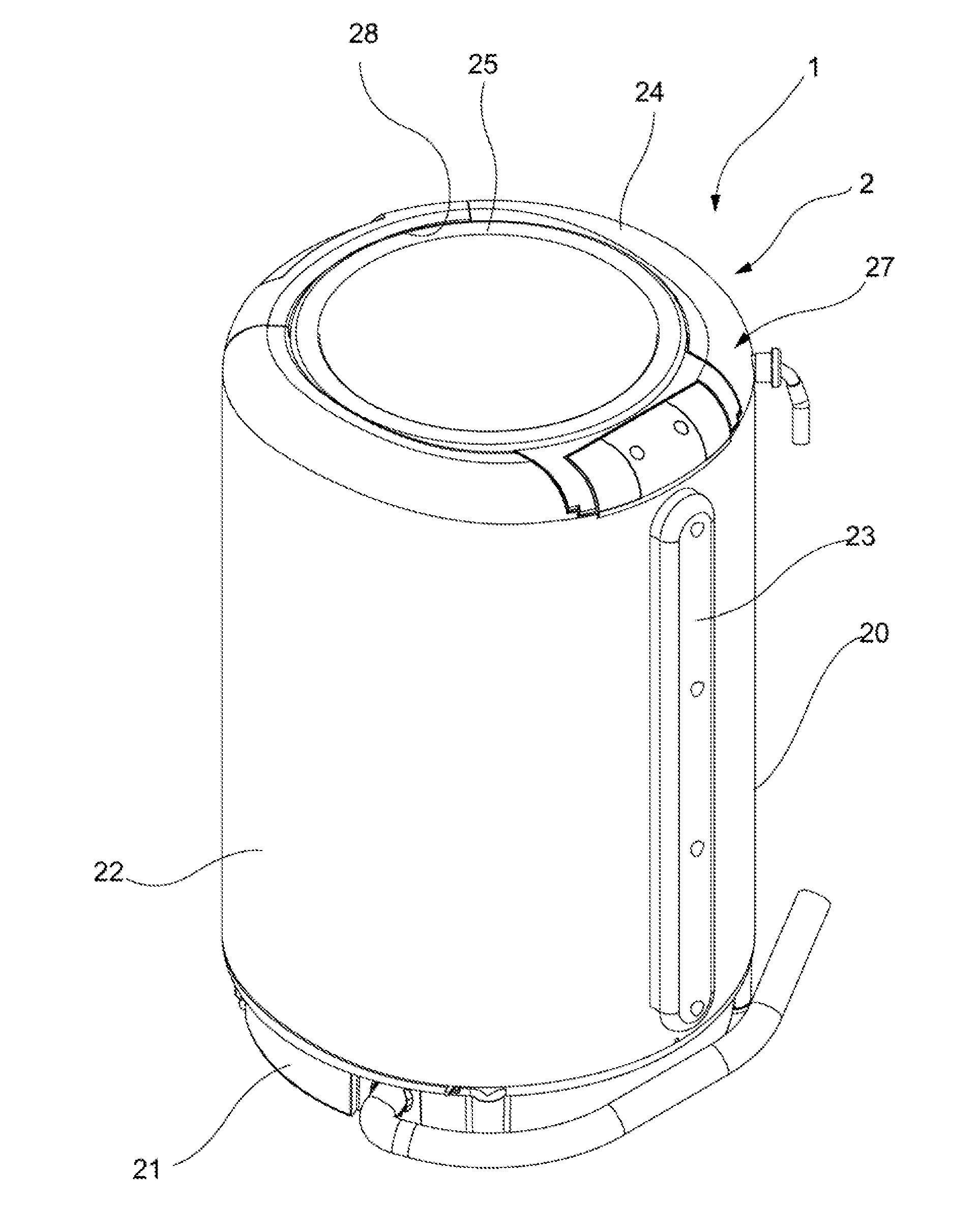
[0021] FIG. 1 is a three-dimensional diagram illustrating an appearance of a washing machine in an embodiment of the present disclosure;
[0022] FIG. 2 is another three-dimensional diagram illustrating the same embodiment;
[0023] FIG. 3 is a side sectional view illustrating the same embodiment;
[0024] FIG. 4 and FIG. 5 are diagrams illustrating effect of the same embodiment; and
[0025] FIG. 6 is an enlarged view illustrating part A in FIG. 3.
A LIST OF REFERENCE NUMERALS
[0026] 1: washing machine; 2: housing; 20: housing body; 22: bottom wall; 24: fixing lid; 25: movable lid; 28: lid side opening; 3: tub; 4: drum; 43: drum side opening; 6: damper; and 7: hopper.
DETAILED DESCRIPTION
[0027] An embodiment of the present disclosure is described in detail below based on drawings.
[0028] FIG. 1 is a three-dimensional diagram illustrating an appearance of a washing machine 1 in the present embodiment. FIG. 2 is an external view illustrating a confirmation state in a washing machine 1 of the present embodiment. In addition, FIG. 3 is a sectional view illustrating a main internal structure of a same washing machine 1. A driving part, a control-related part and a figure of the control-related part of the washing machine 1 are omitted properly in FIG. 3.
[0029] The washing machine 1 in the present embodiment is, for example, suitable for use in families, and includes: a drum 4 for accommodating laundry; a tub 3 for accommodating the drum 4; and a housing 2 for accommodating the drum 4 and the tub 3 in such a manner that visual confirmation can be performed well from an outer side. In addition, besides the tub 3, the drum 4 and the housing 2, the washing machine 1 also includes: a hopper 7 installed at an upper part of the tub 3; a damper 6 installed at a lower side of the tub 3; and a labyrinth-type sealing part 8 arranged between the upper end of the tub 3 and the drum 4.
[0030] The washing machine 1 in the present embodiment includes: a housing 2 having a housing body 20, a fixing lid 24 and a movable lid 25, the housing body 20 is arranged for a purpose of accommodating the tub 3, has a bottom wall 21 supporting the tub 3 from the lower side, and enables the upper end to be opened. The fixing lid 24 is fixed to the upper end of the housing body 20, and the movable lid 25 is movably arranged on the fixing lid 24, enables the upper end of the housing body 20 to be selectively opened outwards and can form a lid side opening 28 which upwards opens the inner drum side opening 43 formed in the upper end part of the drum 4 on the fixing lid 24; a damper 6 vertically arranged from the bottom wall 21, absorbing vibration of the tub 3 and supporting the lower end of the tub 3; and a hopper 7 arranged between the drum side opening 43 and a lid side opening 28 and is configured to guide throwing-in of the laundry from the lid side opening 28 to the drum side opening 43 or taking-out of the laundry from the drum side opening 43 to the cover side opening 28.
[0031] Structures of constitutive elements which form the washing machine 1 are illustrated as follows. Firstly, as shown in FIG. 1 and FIG. 2, the housing 2 is formed with a bottomed approximately-cylindrical shape and is separated from the tub 3 accommodated inside by an approximately uniform dimension when observed from top. The housing 2 includes: a housing body 20 using a cylindrical body 22 which is cylindrical and open at an upper end as a main body; a bottom wall 21 arranged on the housing body 20, i.e., a lower end of the cylindrical body 22 and supporting the tub 3 from the lower side; a fixing lid 24 fixed to the upper end of the housing body 20 and has a circular annular shape when observed from top; and a movable lid 25 has an approximately circular shape when observed from top, movably arranged on the fixing lid 24, enables the upper end of the housing body 20 to be selectively opened outwards and forming a lid side opening 28 which upwards opens the drum side opening 43 formed in the upper end part of the drum 4.
[0032] The housing body 20 includes: a cylindrical body 22 with a cylindrical shape, for example, formed by transparent or semitransparent resin of acrylic acid and the like; a wire cover 23 arranged across the top and bottom of the cylindrical body 22 and configured to accommodate various wires; and a bottom wall 21 indirectly supporting the outer drum 3 from the lower side at a bottom surface side of the housing body 20. The fixing lid 24 has a lid side opening 28 with an approximately circular-shaped opening in a circumferential side, and has a hinging part 26 movably supporting the movable lid 25 in a manner of opening and closing. Moreover, a water supply part 27 is arranged. The water supply part 27 is disposed in a position for displacing from the hinging part 26 to a circumferential direction and is configured to supply water to the drum 4.
[0033] The tub 3 is a bottomed cylindrical component configured in the housing 2, and can store washing water inside. The tub 3 has: a tub body 31 for storing water; a tub cover 32 arranged on an upper end of the tub body 31; and a packing water-sealing part 34 clamped between the tub body 31 and the tub cover 32 and configured to prevent the water from leaking outwards. The packing water-sealing part 34 includes: a water-sealing component 36 arranged on the lower side of the tub cover 32; and a packing component 35 configured to prevent the water from leaking. In addition, nearby specific structures about the packing water-sealing part 34 are described later.
[0034] The drum 4 is a bottomed cylindrical component configured coaxially with the tub 3 in the tub 3 and supported in a manner of free rotation. The drum 4 can generally accommodate laundry inside, and has a plurality of water through holes in a wall surface. As shown in FIG. 3, a balancer 41 protruding inwards in a circular annular shape and three baffles 42 protruding inwards on a lower side of the balancer 41 are arranged on an upper end side of an inner circumferential surface of the drum 4. Then, in a top-loading full automatic washing machine 1 in the present embodiment, a pulsator (agitating wing) 5 driven by a driving device 50 shown by an imaginary line is configured in a manner of free rotation in a bottom center of the drum 4.
[0035] The pulsator 5 generally includes: an approximately disk-shaped pulsator body and a plurality of blade parts formed on an upper surface of the pulsator body. The pulsator 5 agitates the washing water stored in the tub 3 to produce a water flow. With respect to the driving device 50, although the position of the driving device 50 is shown only by the imaginary line in the same figure, a motor not shown is used as a main body so that a driving shaft extending to a bottom of the drum 4 rotates to rotate the drum 4 and the pulsator 5. The washing machine 1 mainly rotates the pulsator 5 in a washing process and rotates the drum 4 and the pulsator 5 integrally at high speed in a dewatering process.
[0036] Then, in the present embodiment, the tub 3 and the drum 4 in the housing 2 are supported on the bottom wall 21 of the housing 2 by means of the damper 6 from the lower side. Then, the tub 3 is not supported by a hoisting rod from a side surface or an upper side. That is, the configuration of the hoisting rod is avoided in the washing machine 1 in the present embodiment, thereby further increasing visual confirmation of the laundry to be observed from the upper side, which will be described in detail subsequently.
[0037] The damper 6 is configured to support the tub 3 in a operating state from a lower side and effectively reduce vibration generated by the tub 3 in the operating state. The damper 6 includes: an inner shaft 61 fixed to the bottom wall 21 of the housing 2; an outer shaft 62 covering an outer side of the inner shaft 61 and fixed to the tub 3 side; and a spring 63 serving as a helical compression spring, arranged between the lower end of the outer shaft 62 and the bottom wall 21 side of the housing 2 and configured to alleviate the vibration transferred to the housing 2 through proper extension and contraction with up and down movement or vibration of the tub 3. In addition, a buffer rubber 64 is arranged between the outer shaft 62 and the tub 3 and between the inner shaft 61 and the bottom wall 21. In the present embodiment, as shown in FIG. 2 and FIG. 3, the damper 6 is configured at a position with a largest diameter or near the position within a range without protrusion, when observed from top, from the bottom of the tub 3. In addition, in the present embodiment, the spring 63 reduces an elastic constant in such a degree that the spring is not close during dewatering and such a degree that the tub 3 is not inclined during operation.
[0038] Then, as mentioned above, in the present embodiment, the hopper 7 is arranged in such a manner of being clamped from an upper side of the tub 3, i.e., specifically from the lid side opening 28 of the fixing lid 24, to the drum side opening 43. As shown in FIG. 2 and FIG. 3, the hopper 7 is arranged between the lid side opening 28 and the drum side opening 43, performs a function as a water receiving guidance component for guiding throwing-in of the laundry from the lid side opening 28 to the drum side opening 43 or taking-out of the laundry from the drum side opening 43 to the lid side opening 28, and is configured to guide throwing-in of the laundry from the lid side opening 28 to the drum side opening 43 or taking-out of the laundry from the drum side opening 43 to the lid side opening 28.
[0039] The hopper 7 is formed by an integrally formed product constituted to be transparent or semitransparent resinaceous, and includes: a hopper body 71 formed in an approximately conical shape, i.e., a conical shape; and an extending part 72 extending from a lower end part of the hopper body 71 to an outer side. A diameter of an opening part as an inner edge of the protrusion part 72 is formed into a diameter approximately matching with the opening at the drum 4 side. In addition, the hopper body 71 includes: a large-diameter upper end part 73 which is open to a greater degree than the drum side opening 43 at the upper end of the hopper body 71; a retracing end 74 arranged on the large-diameter upper end part 73; and an overflow hole 75 which is an opening formed in any position of a middle position in an up-down direction of the hopper body 71 for setting upper limit water levels of the washing process and the rinsing process. When resin material is used as the material, the material with a specific gravity smaller than that of the material used in the tub 3 is also used sometimes for the hopper 7; and thus, compared with the tub 3, the hopper 7 has a light structure.
[0040] Then, as shown in FIG. 2 and FIG. 4, an overflow pipe 76 is connected to the outer side of the overflow hole 75. The overflow pipe 76 is configured to drain water from the overflow hole 75 to the outer side of the washing machine in order to prevent the water from being stored at the upper side of the overflow hole 75. The overflow pipe 76 uses a part which has a bent oval section when observed from top as a main body in order to effectively use a space bent into a circumferential shape between the cylindrical housing 2 and the tub 3. In addition, since a mechanism and a structure for discharging the water from the overflow pipe 76 to the outer side of the washing machine belong to an existing art, the related description is omitted.
[0041] In addition, in the present embodiment, especially as shown in FIG. 4, the inner circumference of the lid side opening 28 of the fixing lid 24 is configured as a shape and size of integrally opening the drum side opening 43 approximately upwards, and the drum side opening 43 arranged in the upper end part of the drum 4 is approximately integrally configured as a shape and a size of upward opening. In other words, an open edge of the lid side opening 28 is located on the outer side of any position of the open edge of the drum side opening 43.
[0042] Then, in the present embodiment, the hopper 7 performs a function as a heightened drum for storing water with a water level higher than the upper end of the drum 4. That is, the hopper 7 performs a function as a washing drum. In addition, in the present embodiment, as mentioned above, since the cylindrical body 22, the movable lid 25 and the hopper 7 of the housing body 20 are configured to be transparent or semitransparent, it is easy to perform visual confirmation on laundry which rise near a water surface of the hopper 7 by means of the fixing lid 24 and perform visual confirmation on laundry near the water surface from the side by means of the cylindrical body 22 and the hopper 7 during washing. In other words, visualization of the laundry is good. In addition, by providing the cylindrical body 22 to be transparent or semitransparent, visualization of internal mechanism components is also increased. Therefore, the grasping of the operating state by a user and the convenience for operations are improved.
[0043] In addition, in the present embodiment, the hopper 7 performs a function as the heightened drum during washing. Since an approximately conical shape, i.e., a conical shape is adopted, and the laundry is guided to the drum 4 as a dewatering drum during dewatering, thereby reliably accommodating the laundry into the drum 4.
[0044] In addition, in the present embodiment, especially as shown in FIG. 5, the damper 6 is provided at the lower part of the tub 3 and the hopper 7 as the heightened drum is formed with a light type, thereby increasing natural vibration frequency of the part supported by the damper 6 and further reducing vibration during dewatering.
[0045] Further, in the present embodiment, the hopper 7 is fixed to the tub 3 and cannot rotate; and on the other hand, undoubtedly, the drum 4 is formed to be rotatable. However, the water does not leak between the drum 4 and the hopper 7.
[0046] That is, in the present embodiment, especially as shown in FIG. 6, the labyrinth-type sealing part 8 is formed across regions of the hopper 7, the tub 3 and the upper end of the drum 4, and includes: an upper side rib 81 arranged on the extending part 72 of the hopper 7 and extending to the lower side of a vertical direction; a lower side rib 82 arranged on the upper end of the drum 4 and extending to the upper side of the vertical direction; and an air retention part 83. The packing component 35 is arranged at the upper end of the tub 3 and is arranged at a position including the upper side of the vertical direction of an imaginary plane of the top part of the upper side rib 81, to seal the upper end of the tub 3 and the extending part 73. Thus, air of the air retention part 83 can be prevented from exceeding the packing component 35 and leaking from the tub 3.
[0047] When the water is accumulated on the upper side of the balancer 41 of the drum 4, a liquid level in the labyrinth sealing part 8 is formed to be in a same plane approximately as the top part of the upper side rib 81, and the air-filled part 83 is formed between the liquid level and the inner circumferential surface of the extending part 72 above the liquid level. By forming the air-filled part 83, even if the water in the hopper 7 moves from a place between the upper and the lower ribs 81 and 82 to the outer side, the water can be inhibited from moving outwards strongly by the air-filled part 83 since the air-filled part is already formed near the packing component 35. In addition, since the packing component 35 is arranged, even if the water exceeds the air-filled part 83 and immerges, the water can be prevented from flowing to the outer side of the tub 3. Thus, the quantity of connecting components required for connecting the tub 3 with the hopper 7 can be effectively reduced.
[0048] As mentioned above, the washing machine 1 in the present embodiment includes: a damper 6 vertically arranged from the bottom wall 21 of the housing 2, absorbing vibration of the tub 3 and supporting the lower end of the tub 3; and a hopper 7 arranged between the drum side opening 43 and a lid side opening 28 and configured to guide throwing-in of the laundry from the lid side opening 28 to the drum side opening 43 or taking-out of the laundry from the drum side opening 43 to the lid side opening 28. Thus, generation of abnormal noise caused by sliding contact between the hoisting rod and the tub 3 is eliminated by removing the hoisting rod; and the damper 6 is provided for supporting near the bottom wall 21 of the housing 2, thereby effectively inhibiting an influence of the vibration caused by an overturning moment on the housing 2. In addition, the hopper 7 is clamped between the housing 2 and the drum 4; and even if a distance between the drum side opening 43 and the lid side opening 28 is increased, taking-out and throwing-in of laundry can be properly guided.
[0049] In addition, according to the present embodiment, the hopper 7 is formed in an approximately conical shape, and includes: a lower end part connected with an upper end part of the drum 4; and a large-diameter upper end part 73 formed with a diameter which gradually increases upwards from the lower end part. In other words, an inverted truncated cone shape or an approximate mortar shape is adopted. Therefore, an opening area of the upper end part of the hopper 7 can be obtained more broadly than the drum 4, thereby further enhancing convenience of taking-out and throwing-in of the laundry.
[0050] Further, according to the present embodiment, at least part of the housing 2 and the hopper 7 are provided to be transparent or semitransparent. Therefore, except a design appearance, visualization of a washing state and visual confirmation of a fault part can be enhanced.
[0051] In addition, according to the present embodiment, the hopper 7 is made of the material with a specific gravity smaller than that of the materials of the tub 3 and the drum 4. Therefore, components supported by the damper 6 have light weight, thereby increasing natural vibration frequency of the part supported by the damper 6 and reducing vibration during general dewatering.
[0052] Then, according to the present embodiment, the hopper 7 performs a function as the heightened drum for storing the water with a water level higher than the upper end of the drum 4. Therefore, the same effect as the washing machine with a simple structure and an increased volume of the drum 4 can be obtained.
[0053] In addition, according to the present embodiment, the hopper 7 includes: an extending part 72 extending from an inner circumference of the tub 3 to the drum side opening 43; and a hopper body 71 integrally arranged vertically from the extending part 72. Therefore, although the material with light weight is used, the strength of the hopper 7 is effectively enhanced since the shape of the material is difficult to be bent.
[0054] Although an embodiment of the present disclosure is described above, the structure of the present embodiment is not limited to the above-mentioned contents and can be varied in any forms.
[0055] For example, in above embodiments, a structure configured with three dampers is disclosed. However, undoubtedly, a manner of more than four dampers can also be applied as long as the manner supports the tub.
[0056] In addition, in above embodiments, the structure that the hopper is fixed to the tub is disclosed. However, undoubtedly, a structure that the hopper is configured at the housing side can be adopted. Specifically, the structure that the hopper is fixed to the fixing lid and the housing body is adopted.
[0057] Various variations can also be made to other structures without departing from the scope of the spirit of the present disclosure.
* * * * *
D00000
D00001
D00002
D00003
D00004
D00005
D00006
XML
uspto.report is an independent third-party trademark research tool that is not affiliated, endorsed, or sponsored by the United States Patent and Trademark Office (USPTO) or any other governmental organization. The information provided by uspto.report is based on publicly available data at the time of writing and is intended for informational purposes only.
While we strive to provide accurate and up-to-date information, we do not guarantee the accuracy, completeness, reliability, or suitability of the information displayed on this site. The use of this site is at your own risk. Any reliance you place on such information is therefore strictly at your own risk.
All official trademark data, including owner information, should be verified by visiting the official USPTO website at www.uspto.gov. This site is not intended to replace professional legal advice and should not be used as a substitute for consulting with a legal professional who is knowledgeable about trademark law.