Removable Printhead
Tan; Liling ; et al.
U.S. patent application number 15/628727 was filed with the patent office on 2018-12-27 for removable printhead. The applicant listed for this patent is Datamax-O'Neil Corporation. Invention is credited to Kenneth Colonel, Liling Tan.
| Application Number | 20180370261 15/628727 |
| Document ID | / |
| Family ID | 64691823 |
| Filed Date | 2018-12-27 |

| United States Patent Application | 20180370261 |
| Kind Code | A1 |
| Tan; Liling ; et al. | December 27, 2018 |
REMOVABLE PRINTHEAD
Abstract
A printhead mounting system includes one or more pins attached to a printhead, and configured to be inserted through one or more slots in a support frame coupled to a printer, and one or more fasteners configured to engage with the pins inserted through the support frame slots. The fasteners can be detachable, operably coupled to the support frame, or coupled to each other. Additionally, the system can have locating pins for aligning the printhead with the support frame. A method for attaching a printhead includes inserting posts located at a top of a printhead through openings in a printhead support frame, and engaging one or more quick-release fasteners with the posts above the support frame.
| Inventors: | Tan; Liling; (Singapore, SG) ; Colonel; Kenneth; (Oviedo, FL) | ||||||||||
| Applicant: |
|
||||||||||
|---|---|---|---|---|---|---|---|---|---|---|---|
| Family ID: | 64691823 | ||||||||||
| Appl. No.: | 15/628727 | ||||||||||
| Filed: | June 21, 2017 |
| Current U.S. Class: | 1/1 |
| Current CPC Class: | B41J 11/006 20130101; B41J 2/33505 20130101; B41J 2202/31 20130101; B41J 2/32 20130101; B41J 25/312 20130101; B41J 25/34 20130101; B41J 2/325 20130101 |
| International Class: | B41J 25/312 20060101 B41J025/312; B41J 25/34 20060101 B41J025/34; B41J 11/00 20060101 B41J011/00; B41J 2/335 20060101 B41J002/335 |
Claims
1. A printhead mounting assembly, comprising: a printhead having a longitudinal axis, a top face and a bottom face; one or more support posts mechanically coupled to the top face of the printhead at a predetermined distance along the longitudinal axis; a support bracket having a longitudinal axis, a top face and a bottom face; wherein the bracket includes one or more openings located at a distance matching the predetermined distance between the support posts, and is configured to support the printhead in a mounted position when the support posts are inserted through the openings from the bottom face of the bracket; and one or more retention clips configured to engage with the one or more support posts to affix the printhead to the support bracket coupled to a printer when the printhead is in the mounted position, and to disengage to release the printhead from the support bracket.
2. The assembly according to claim 1, wherein the retention clips include a locking assembly configured to secure the clips being engaged with the support posts.
3. The assembly according to claim 1, wherein the support posts include one or more grooves configured to secure the retention clips being engaged with the support posts.
4. The assembly according to claim 1, wherein the support posts and/or the retention clips include steel.
5. A printhead mounting system, comprising: one or more pins attached to a printhead, and configured to be inserted through one or more slots in a bracket coupled to a printer; and one or more fasteners configured to engage with the one or more pins inserted through the bracket slots.
6. The system according to claim 5, wherein the fasteners comprise metal clips.
7. The system according to claim 6, wherein the metal clips include an opening to accommodate the pin, and one or more tabs configured to secure the pin in the engaged position.
8. The system according to claim 5, wherein the one or more fasteners include one or more spring wires.
9. The system according to claim 8, wherein a top of the pin includes a chamfer configured to allow the spring wire to displace and snap into the slot when the printhead is pressed against the bracket.
10. The system according to claim 5, wherein the one or more pins comprise a shaft having one or more grooves configured to engage with the fasteners.
11. The system according to claim 5, further including a locating assembly configured to align the printhead and the bracket.
12. The system according to claim 5, wherein the fasteners include spring sheet material.
13. The system according to claim 5, wherein the fasteners have a minimum Rockwell hardness of C40.
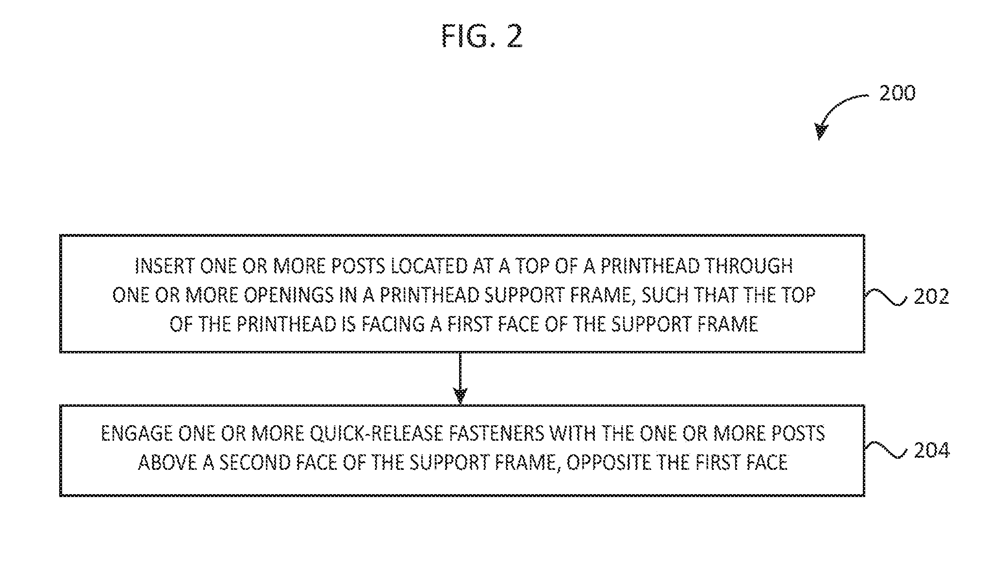
14. A method for attaching a printhead, comprising: inserting one or more posts located at a top of a printhead through one or more openings in a printhead support frame, such that the top of the printhead is facing a first face of the support frame; and engaging one or more quick-release fasteners with the one or more posts above a second face of the support frame, opposite the first face.
15. The method according to claim 14, wherein engaging the quick-release fasteners includes sliding the post through a slot in a bottom part of the fastener, and securing the post by placing a top part of the fastener over the post.
16. The method according to claim 14, wherein engaging the quick-release fasteners includes engaging detachable fasteners.
17. The method according to claim 14, wherein engaging the quick-release fasteners includes engaging fasteners operably coupled to the support frame.
18. The method according to claim 14, wherein engaging the quick-release fasteners includes engaging one or more fasteners coupled together.
19. The method according to claim 14, further including using one or more locating pins to align the printhead with the support frame.
20. The method according to claim 14, wherein engaging the quick-release fasteners includes having one or more spring wires to displace and snap into the one or more openings.
Description
FIELD OF THE INVENTION
[0001] The present invention relates to thermal printing, and more particularly to printhead mounting assemblies, and methods of attaching a printhead.
BACKGROUND
[0002] Generally speaking, thermal printers operate using printheads fastened to brackets. Whenever such printhead assemblies are replaced, the printhead is removed along with the bracket. Standard means of attaching a printhead include a printhead firmly attached to a bracket, wherein the bracket is also coupled with a ribbon diverting shaft and shaft lock clip. To replace a printhead, the whole assembly needs to be removed. To avoid the unnecessary wastage of brackets, a printhead assembly capable of disengaging the printhead from the bracket is needed.
[0003] Several attempts have been made to address this issue. For example, U.S. Pat. No. 8,366,335 by Colquitt et al. discloses a platen roller assembly for a printer having a platen roller, a retaining clip, a plurality of bearings, and a pulley assembly. In order to remove the platen roller, a screw assembly is removed by unscrewing a clip. While the reference mentions using a clip to hold together the components, the clip is not used for easy attachment/removal of the printhead to/from the bracket. U.S. Pat. No. 7,399,130 by Hirte et al. discloses a printer with quick release printhead and platen. The reference discloses guide tabs of a printhead support structure, which mate with guide slots of the printhead bracket. The assembly aligns the printhead with the platen using a pair of alignment pins projecting from the bracket, and secures it with fasteners. However, the reference does not mention any particular features of the pins (e.g., an undercut) meant for securing the retention clip in place. E.P. Pat. No. 1,055,522 by Barrus et al. discloses a thermal printer with improved ribbon transport. The reference discloses a structure where a pair of pins rises from a bottom of a gimbal plate to stabilize it. A gimbaled roller is supported in a set of bearing housings, which are attached by screws or other fastening means. Although the reference mentions a method of connecting the gimbal plate to the assembly, it does not specifically mention connecting the printhead and a bracket. Additionally, retention is performed by using nuts or screws, and not retention clips or other quick-release mechanisms.
[0004] Therefore, a need exists for a system and a method for easily attaching and removing a printhead.
SUMMARY
[0005] Accordingly, in one aspect, the present invention embraces printhead mounting assemblies, and a method of attaching a printhead.
[0006] In an exemplary embodiment, a printhead mounting assembly includes a printhead with one or more support posts; a support bracket having one or more openings located at a distance matching the distance between the support posts, and configured to support the printhead in a mounted position when the support posts are inserted through the openings of the bracket; and one or more retention clips configured to engage with the one or more support posts to affix the printhead to the support bracket coupled to a printer when the printhead is in the mounted position, and to disengage to release the printhead from the support bracket.
[0007] In another exemplary embodiment, a printhead mounting system includes one or more pins attached to a printhead, and configured to be inserted through one or more slots in a bracket coupled to a printer; and one or more fasteners configured to engage with the one or more pins inserted through the bracket slots.
[0008] In another aspect, the present invention embraces a method for attaching a printhead. The method includes inserting one or more posts located at a top of a printhead through one or more openings in a printhead support frame; and engaging one or more quick-release fasteners with the one or more posts above the support frame.
[0009] The foregoing illustrative summary, as well as other exemplary objectives and/or advantages of the invention, and the manner in which the same are accomplished, are further explained within the following detailed description and its accompanying drawings.
BRIEF DESCRIPTION OF THE DRAWINGS
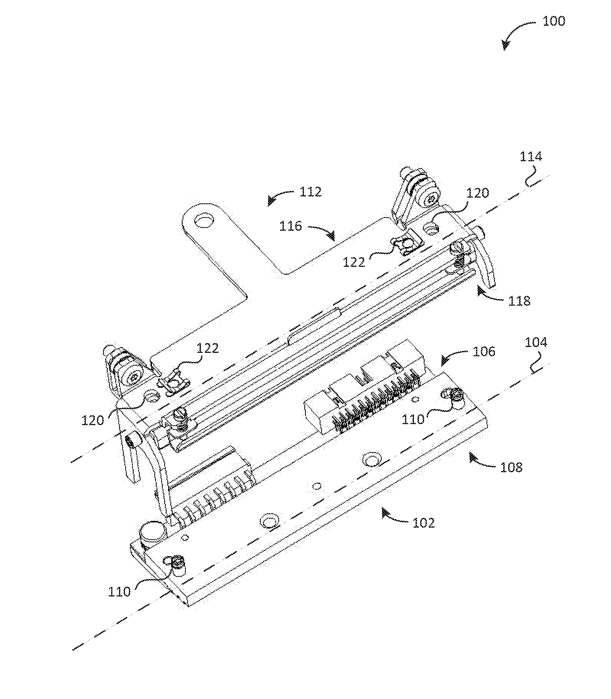
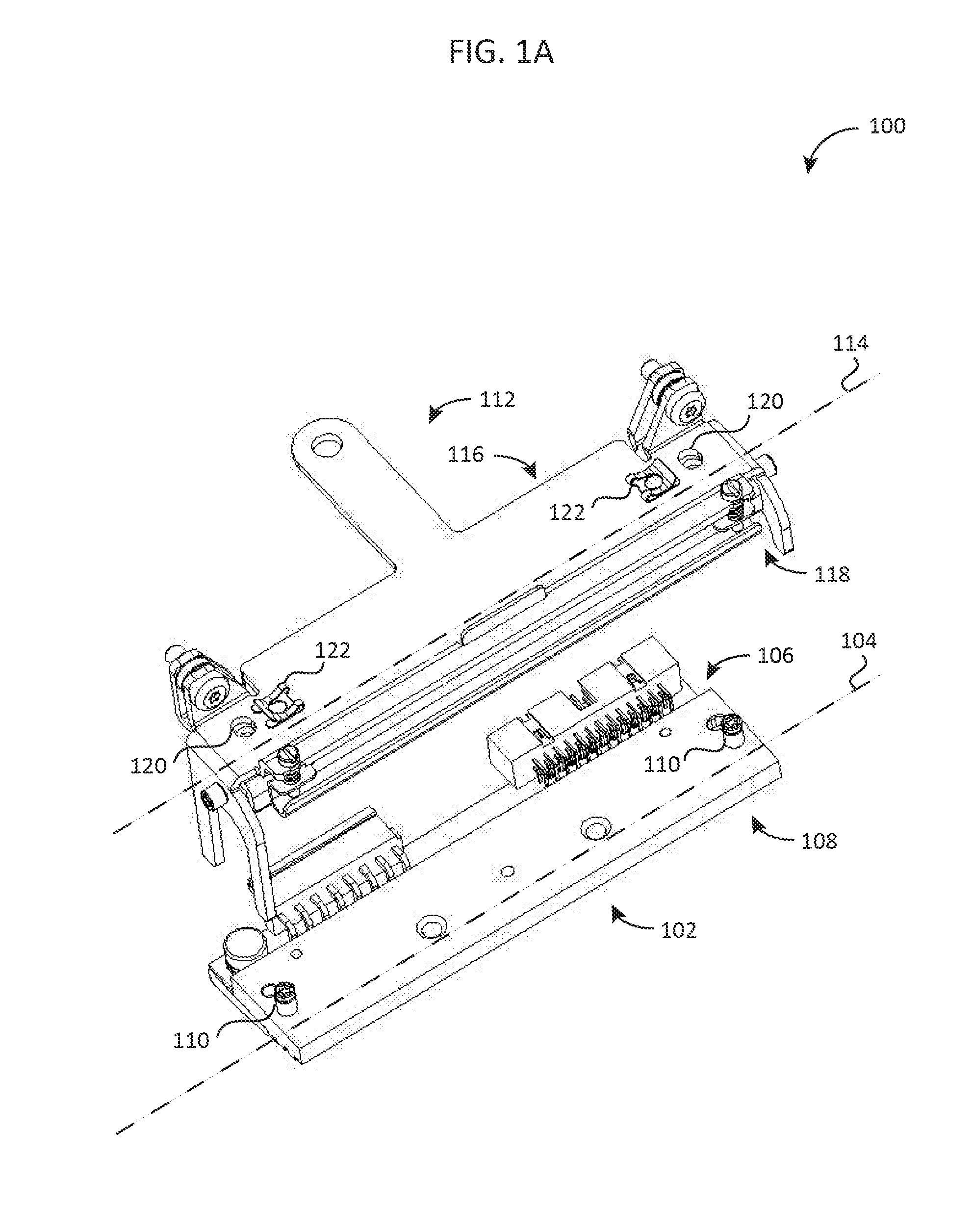
[0010] FIG. 1A graphically depicts a printhead mounting assembly in a dismounted position, according to an embodiment.
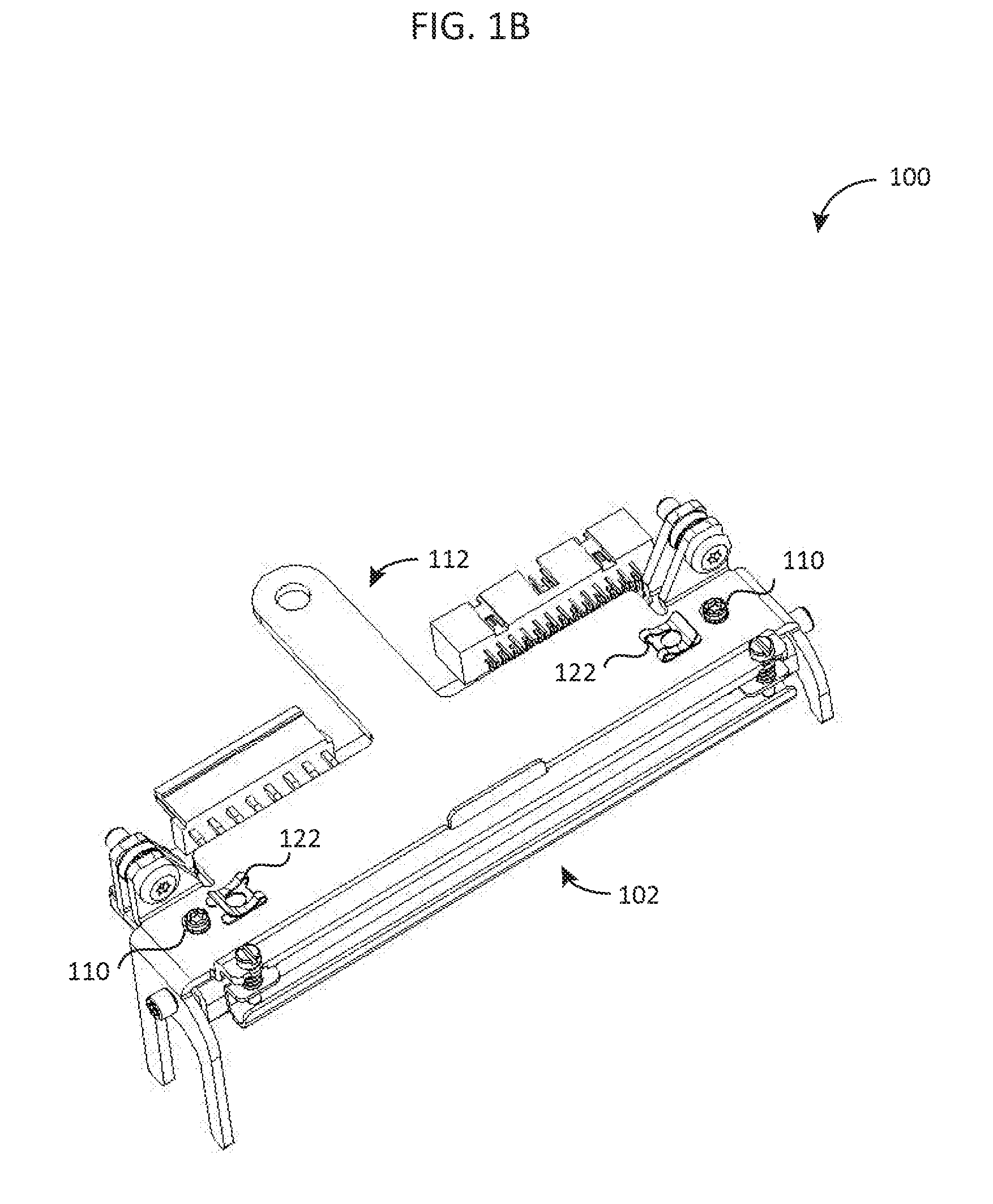
[0011] FIG. 1B graphically depicts a printhead mounting assembly with disengaged retention clips, according to an embodiment.
[0012] FIG. 1C graphically depicts a printhead mounting assembly in a fully mounted position, according to an embodiment.
[0013] FIG. 2 schematically depicts a method for attaching a printhead, according to an embodiment.
DETAILED DESCRIPTION
[0014] The present invention embraces a system and method for mounting a printhead.
[0015] FIGS. 1A-1C show a printhead mounting assembly 100, according to an embodiment. The assembly 100 includes a printhead 102 having a longitudinal axis 104, a top face 106, and a bottom face 108. One or more support posts 110 are mechanically coupled to the top face 106 of the printhead 102 at a predetermined distance along the longitudinal axis 104. A support bracket 112 has a longitudinal axis 114, a top face 116, and a bottom face 118. The bracket 112 includes one or more openings 120 located at a distance matching the predetermined distance between the support posts 110, and is configured to support the printhead 102 in a mounted position when the support posts 110 are inserted through the openings 120 from the bottom face 118 of the bracket 112. One or more retention clips 122 are configured to engage with the one or more support posts 110 to affix the printhead 102 to the support bracket 112 coupled to a printer (not shown) when the printhead 102 is in the mounted position, and to disengage to release the printhead 102 from the support bracket 112. Specifically, FIG. 1A shows a printhead mounting assembly 100 in a dismounted position, where the printhead 102 is separated from the bracket 112. FIG. 1B shows a printhead mounting assembly 100 with disengaged retention clips 122. FIG. 1C shows a printhead mounting assembly 100 in a fully mounted position with the retention clips 122 engaged with the support posts 110, according to an embodiment.
[0016] In an embodiment, the retention clips 122 can include a locking assembly configured to secure the clips being engaged with the support posts. The support posts 110 can include one or more grooves configured to secure the retention clips 122 being engaged with the support posts 110. The support posts 110 and/or the retention clips 122 can include steel.
[0017] In an exemplary embodiment, a printhead mounting system 200 can include one or more pins attached to a printhead, and configured to be inserted through one or more slots in a bracket coupled to a printer; and one or more fasteners configured to engage with the one or more pins inserted through the bracket slots.
[0018] In an embodiment, the fasteners can comprise metal clips. The metal clips can include an opening to accommodate the pin, and one or more tabs configured to secure the pin in the engaged position. The one or more fasteners can include one or more spring wires. The fasteners can include spring sheet material, and/or have a minimum Rockwell hardness of C40. A top of the pin can include a chamfer configured to allow the spring wire to displace and snap into the slot when the printhead is pressed against the bracket. Additionally or alternatively, the one or more pins can include a shaft having one or more grooves configured to engage with the fasteners. The system 200 can further include a locating assembly configured to align the printhead and the bracket.
[0019] In an embodiment, the support posts 110 can be asymmetrical or located at different distance from a centerline of the printhead 102. For example, mechanical features can be used, such as different size pins or features, as well as male and female features that present an obvious orientation of the printhead 102 to the support bracket 112. In an embodiment, some or all of the support posts 110 can be cylindrical, triangular, or other type and/or shape; additionally, posts of several types, sizes, and/or shapes can be used simultaneously.
[0020] In an embodiment, mechanical locking can be performed with a positive interlocking feature configured to secure the printhead 102 in place. For example, two retention clips 122 can be coupled or produced as a single sliding part. In which case, a separate motion by the operator to slide the retention clip into place may be required. Additionally or alternatively, a spring wire or ball detent can be used to provide a positive locking without requiring an additional motion. The compliant member of the ball detent or spring wire can provide the motion through its deflection. The detent member can then be moved by the user to relieve the retention force holding the printhead 102 with the support bracket 112 in place.
[0021] FIG. 2 shows a method 300 for attaching a printhead, according to an embodiment. At 302, one or more posts located at a top of a printhead are inserted through one or more openings in a printhead support frame, such that the top of the printhead is facing a first face of the support frame. At 304, one or more quick-release fasteners are engaged with the one or more posts above a second face of the support frame, opposite the first face.
[0022] In an embodiment, engaging the quick-release fasteners at 304 can include sliding the post through a slot in a bottom part of the fastener, and securing the post by placing a top part of the fastener over the post. Additionally or alternatively, engaging the quick-release fasteners can include engaging detachable fasteners. In an embodiment, the quick-release fasteners can be operably coupled to the support frame. Additionally or alternatively, engaging the quick-release fasteners at 304 can include engaging one or more fasteners coupled together. The method 300 can further include using one or more locating pins to align the printhead with the support frame. Additionally, engaging the quick-release fasteners can include having one or more spring wires to displace and snap into the one or more openings.
[0023] As used herein, the terms pin, post, screw and fastener may be used interchangeably and considered synonymous depending on the context, unless further definition is provided. Additionally, used herein, the terms clip and quick-release fastener may be used interchangeably and considered synonymous depending on the context, unless further definition is provided.
[0024] Device and method components are meant to show only those specific details that are pertinent to understanding the embodiments of the present disclosure so as not to obscure the disclosure with details that will be readily apparent to those of ordinary skill in the art having the benefit of the description herein. In various embodiments, the sequence in which the elements of appear in exemplary embodiments disclosed herein may vary. Two or more method steps may be performed simultaneously or in a different order than the sequence in which the elements appear in the exemplary embodiments.
[0025] To supplement the present disclosure, this application incorporates entirely by reference the following commonly assigned patents, patent application publications, and patent applications: [0026] U.S. Pat. No. 6,832,725; U.S. Pat. No. 7,128,266; [0027] U.S. Pat. No. 7,159,783; U.S. Pat. No. 7,413,127; [0028] U.S. Pat. No. 7,726,575; U.S. Pat. No. 8,294,969; [0029] U.S. Pat. No. 8,317,105; U.S. Pat. No. 8,322,622; [0030] U.S. Pat. No. 8,366,005; U.S. Pat. No. 8,371,507; [0031] U.S. Pat. No. 8,376,233; U.S. Pat. No. 8,381,979; [0032] U.S. Pat. No. 8,390,909; U.S. Pat. No. 8,408,464; [0033] U.S. Pat. No. 8,408,468; U.S. Pat. No. 8,408,469; [0034] U.S. Pat. No. 8,424,768; U.S. Pat. No. 8,448,863; [0035] U.S. Pat. No. 8,457,013; U.S. Pat. No. 8,459,557; [0036] U.S. Pat. No. 8,469,272; U.S. Pat. No. 8,474,712; [0037] U.S. Pat. No. 8,479,992; U.S. Pat. No. 8,490,877; [0038] U.S. Pat. No. 8,517,271; U.S. Pat. No. 8,523,076; [0039] U.S. Pat. No. 8,528,818; U.S. Pat. No. 8,544,737; [0040] U.S. Pat. No. 8,548,242; U.S. Pat. No. 8,548,420; [0041] U.S. Pat. No. 8,550,335; U.S. Pat. No. 8,550,354; [0042] U.S. Pat. No. 8,550,357; U.S. Pat. No. 8,556,174; [0043] U.S. Pat. No. 8,556,176; U.S. Pat. No. 8,556,177; [0044] U.S. Pat. No. 8,559,767; U.S. Pat. No. 8,599,957; [0045] U.S. Pat. No. 8,561,895; U.S. Pat. No. 8,561,903; [0046] U.S. Pat. No. 8,561,905; U.S. Pat. No. 8,565,107; [0047] U.S. Pat. No. 8,571,307; U.S. Pat. No. 8,579,200; [0048] U.S. Pat. No. 8,583,924; U.S. Pat. No. 8,584,945; [0049] U.S. Pat. No. 8,587,595; U.S. Pat. No. 8,587,697; [0050] U.S. Pat. No. 8,588,869; U.S. Pat. No. 8,590,789; [0051] U.S. Pat. No. 8,596,539; U.S. Pat. No. 8,596,542; [0052] U.S. Pat. No. 8,596,543; U.S. Pat. No. 8,599,271; [0053] U.S. Pat. No. 8,599,957; U.S. Pat. No. 8,600,158; [0054] U.S. Pat. No. 8,600,167; U.S. Pat. No. 8,602,309; [0055] U.S. Pat. No. 8,608,053; U.S. Pat. No. 8,608,071; [0056] U.S. Pat. No. 8,611,309; U.S. Pat. No. 8,615,487; [0057] U.S. Pat. No. 8,616,454; U.S. Pat. No. 8,621,123; [0058] U.S. Pat. No. 8,622,303; U.S. Pat. No. 8,628,013; [0059] U.S. Pat. No. 8,628,015; U.S. Pat. No. 8,628,016; [0060] U.S. Pat. No. 8,629,926; U.S. Pat. No. 8,630,491; [0061] U.S. Pat. No. 8,635,309; U.S. Pat. No. 8,636,200; [0062] U.S. Pat. No. 8,636,212; U.S. Pat. No. 8,636,215; [0063] U.S. Pat. No. 8,636,224; U.S. Pat. No. 8,638,806; [0064] U.S. Pat. No. 8,640,958; U.S. Pat. No. 8,640,960; [0065] U.S. Pat. No. 8,643,717; U.S. Pat. No. 8,646,692; [0066] U.S. Pat. No. 8,646,694; U.S. Pat. No. 8,657,200; [0067] U.S. Pat. No. 8,659,397; U.S. Pat. No. 8,668,149; [0068] U.S. Pat. No. 8,678,285; U.S. Pat. No. 8,678,286; [0069] U.S. Pat. No. 8,682,077; U.S. Pat. No. 8,687,282; [0070] U.S. Pat. No. 8,692,927; U.S. Pat. No. 8,695,880; [0071] U.S. Pat. No. 8,698,949; U.S. Pat. No. 8,717,494; [0072] U.S. Pat. No. 8,717,494; U.S. Pat. No. 8,720,783; [0073] U.S. Pat. No. 8,723,804; U.S. Pat. No. 8,723,904; [0074] U.S. Pat. No. 8,727,223; U.S. Pat. No. D702,237; [0075] U.S. Pat. No. 8,740,082; U.S. Pat. No. 8,740,085; [0076] U.S. Pat. No. 8,746,563; U.S. Pat. No. 8,750,445; [0077] U.S. Pat. No. 8,752,766; U.S. Pat. No. 8,756,059; [0078] U.S. Pat. No. 8,757,495; U.S. Pat. No. 8,760,563; [0079] U.S. Pat. No. 8,763,909; U.S. Pat. No. 8,777,108; [0080] U.S. Pat. No. 8,777,109; U.S. Pat. No. 8,779,898; [0081] U.S. Pat. No. 8,781,520; U.S. Pat. No. 8,783,573; [0082] U.S. Pat. No. 8,789,757; U.S. Pat. No. 8,789,758; [0083] U.S. Pat. No. 8,789,759; U.S. Pat. No. 8,794,520; [0084] U.S. Pat. No. 8,794,522; U.S. Pat. No. 8,794,525; [0085] U.S. Pat. No. 8,794,526; U.S. Pat. No. 8,798,367; [0086] U.S. Pat. No. 8,807,431; U.S. Pat. No. 8,807,432; [0087] U.S. Pat. No. 8,820,630; U.S. Pat. No. 8,822,848; [0088] U.S. Pat. No. 8,824,692; U.S. Pat. No. 8,824,696; [0089] U.S. Pat. No. 8,842,849; U.S. Pat. No. 8,844,822; [0090] U.S. Pat. No. 8,844,823; U.S. Pat. No. 8,849,019; [0091] U.S. Pat. No. 8,851,383; U.S. Pat. No. 8,854,633; [0092] U.S. Pat. No. 8,866,963; U.S. Pat. No. 8,868,421; [0093] U.S. Pat. No. 8,868,519; U.S. Pat. No. 8,868,802; [0094] U.S. Pat. No. 8,868,803; U.S. Pat. No. 8,870,074; [0095] U.S. Pat. No. 8,879,639; U.S. Pat. No. 8,880,426; [0096] U.S. Pat. No. 8,881,983; U.S. Pat. No. 8,881,987; [0097] U.S. Pat. No. 8,903,172; U.S. Pat. No. 8,908,995; [0098] U.S. Pat. No. 8,910,870; U.S. Pat. No. 8,910,875; [0099] U.S. Pat. No. 8,914,290; U.S. Pat. No. 8,914,788; [0100] U.S. Pat. No. 8,915,439; U.S. Pat. No. 8,915,444; [0101] U.S. Pat. No. 8,916,789; U.S. Pat. No. 8,918,250; [0102] U.S. Pat. No. 8,918,564; U.S. Pat. No. 8,925,818; [0103] U.S. Pat. No. 8,939,374; U.S. Pat. No. 8,942,480; [0104] U.S. Pat. No. 8,944,313; U.S. Pat. No. 8,944,327; [0105] U.S. Pat. No. 8,944,332; U.S. Pat. No. 8,950,678; [0106] U.S. Pat. No. 8,967,468; U.S. Pat. No. 8,971,346; [0107] U.S. Pat. No. 8,976,030; U.S. Pat. No. 8,976,368; [0108] U.S. Pat. No. 8,978,981; U.S. Pat. No. 8,978,983; [0109] U.S. Pat. No. 8,978,984; U.S. Pat. No. 8,985,456; [0110] U.S. Pat. No. 8,985,457; U.S. Pat. No. 8,985,459; [0111] U.S. Pat. No. 8,985,461; U.S. Pat. No. 8,988,578; [0112] U.S. Pat. No. 8,988,590; U.S. Pat. No. 8,991,704; [0113] U.S. Pat. No. 8,996,194; U.S. Pat. No. 8,996,384; [0114] U.S. Pat. No. 9,002,641; U.S. Pat. No. 9,007,368; [0115] U.S. Pat. No. 9,010,641; U.S. Pat. No. 9,015,513; [0116] U.S. Pat. No. 9,016,576; U.S. Pat. No. 9,022,288; [0117] U.S. Pat. No. 9,030,964; U.S. Pat. No. 9,033,240; [0118] U.S. Pat. No. 9,033,242; U.S. Pat. No. 9,036,054; [0119] U.S. Pat. No. 9,037,344; U.S. Pat. No. 9,038,911; [0120] U.S. Pat. No. 9,038,915; U.S. Pat. No. 9,047,098; [0121] U.S. Pat. No. 9,047,359; U.S. Pat. No. 9,047,420; [0122] U.S. Pat. No. 9,047,525; U.S. Pat. No. 9,047,531; [0123] U.S. Pat. No. 9,053,055; U.S. Pat. No. 9,053,378; [0124] U.S. Pat. No. 9,053,380; U.S. Pat. No. 9,058,526; [0125] U.S. Pat. No. 9,064,165; U.S. Pat. No. 9,064,167; [0126] U.S. Pat. No. 9,064,168; U.S. Pat. No. 9,064,254; [0127] U.S. Pat. No. 9,066,032; U.S. Pat. No. 9,070,032; [0128] U.S. Design Pat. No. D716,285; [0129] U.S. Design Pat. No. D723,560; [0130] U.S. Design Pat. No. D730,357; [0131] U.S. Design Pat. No. D730,901; [0132] U.S. Design Pat. No. D730,902; [0133] U.S. Design Pat. No. D733,112; [0134] U.S. Design Pat. No. D734,339; [0135] International Publication No. 2013/163789; [0136] International Publication No. 2013/173985; [0137] International Publication No. 2014/019130; [0138] International Publication No. 2014/110495; [0139] U.S. Patent Application Publication No. 2008/0185432; [0140] U.S. Patent Application Publication No. 2009/0134221; [0141] U.S. Patent Application Publication No. 2010/0177080; [0142] U.S. Patent Application Publication No. 2010/0177076; [0143] U.S. Patent Application Publication No. 2010/0177707; [0144] U.S. Patent Application Publication No. 2010/0177749; [0145] U.S. Patent Application Publication No. 2010/0265880; [0146] U.S. Patent Application Publication No. 2011/0202554; [0147] U.S. Patent Application Publication No. 2012/0111946; [0148] U.S. Patent Application Publication No. 2012/0168511; [0149] U.S. Patent Application Publication No. 2012/0168512; [0150] U.S. Patent Application Publication No. 2012/0193423; [0151] U.S. Patent Application Publication No. 2012/0203647; [0152] U.S. Patent Application Publication No. 2012/0223141; [0153] U.S. Patent Application Publication No. 2012/0228382; [0154] U.S. Patent Application Publication No. 2012/0248188; [0155] U.S. Patent Application Publication No. 2013/0043312; [0156] U.S. Patent Application Publication No. 2013/0082104; [0157] U.S. Patent Application Publication No. 2013/0175341; [0158] U.S. Patent Application Publication No. 2013/0175343; [0159] U.S. Patent Application Publication No. 2013/0257744; [0160] U.S. Patent Application Publication No. 2013/0257759; [0161] U.S. Patent Application Publication No. 2013/0270346; [0162] U.S. Patent Application Publication No. 2013/0287258; [0163] U.S. Patent Application Publication No. 2013/0292475; [0164] U.S. Patent Application Publication No. 2013/0292477; [0165] U.S. Patent Application Publication No. 2013/0293539; [0166] U.S. Patent Application Publication No. 2013/0293540; [0167] U.S. Patent Application Publication No. 2013/0306728; [0168] U.S. Patent Application Publication No. 2013/0306731; [0169] U.S. Patent Application Publication No. 2013/0307964; [0170] U.S. Patent Application Publication No. 2013/0308625; [0171] U.S. Patent Application Publication No. 2013/0313324; [0172] U.S. Patent Application Publication No. 2013/0313325; [0173] U.S. Patent Application Publication No. 2013/0342717; [0174] U.S. Patent Application Publication No. 2014/0001267; [0175] U.S. Patent Application Publication No. 2014/0008439; [0176] U.S. Patent Application Publication No. 2014/0025584; [0177] U.S. Patent Application Publication No. 2014/0034734; [0178] U.S. Patent Application Publication No. 2014/0036848; [0179] U.S. Patent Application Publication No. 2014/0039693; [0180] U.S. Patent Application Publication No. 2014/0042814; [0181] U.S. Patent Application Publication No. 2014/0049120; [0182] U.S. Patent Application Publication No. 2014/0049635; [0183] U.S. Patent Application Publication No. 2014/0061306; [0184] U.S. Patent Application Publication No. 2014/0063289; [0185] U.S. Patent Application Publication No. 2014/0066136; [0186] U.S. Patent Application Publication No. 2014/0067692; [0187] U.S. Patent Application Publication No. 2014/0070005; [0188] U.S. Patent Application Publication No. 2014/0071840; [0189] U.S. Patent Application Publication No. 2014/0074746; [0190] U.S. Patent Application Publication No. 2014/0076974; [0191] U.S. Patent Application Publication No. 2014/0078341; [0192] U.S. Patent Application Publication No. 2014/0078345; [0193] U.S. Patent Application Publication No. 2014/0097249; [0194] U.S. Patent Application Publication No. 2014/0098792; [0195] U.S. Patent Application Publication No. 2014/0100813; [0196] U.S. Patent Application Publication No. 2014/0103115; [0197] U.S. Patent Application Publication No. 2014/0104413; [0198] U.S. Patent Application Publication No. 2014/0104414; [0199] U.S. Patent Application Publication No. 2014/0104416; [0200] U.S. Patent Application Publication No. 2014/0104451; [0201] U.S. Patent Application Publication No. 2014/0106594; [0202] U.S. Patent Application Publication No. 2014/0106725; [0203] U.S. Patent Application Publication No. 2014/0108010; [0204] U.S. Patent Application Publication No. 2014/0108402; [0205] U.S. Patent Application Publication No. 2014/0110485; [0206] U.S. Patent Application Publication No. 2014/0114530; [0207] U.S. Patent Application Publication No. 2014/0124577; [0208] U.S. Patent Application Publication No. 2014/0124579; [0209] U.S. Patent Application Publication No. 2014/0125842; [0210] U.S. Patent Application Publication No. 2014/0125853; [0211] U.S. Patent Application Publication No. 2014/0125999; [0212] U.S. Patent Application Publication No. 2014/0129378; [0213] U.S. Patent Application Publication No. 2014/0131438; [0214] U.S. Patent Application Publication No. 2014/0131441; [0215] U.S. Patent Application Publication No. 2014/0131443; [0216] U.S. Patent Application Publication No. 2014/0131444; [0217] U.S. Patent Application Publication No. 2014/0131445; [0218] U.S. Patent Application Publication No. 2014/0131448; [0219] U.S. Patent Application Publication No. 2014/0133379; [0220] U.S. Patent Application Publication No. 2014/0136208; [0221] U.S. Patent Application Publication No. 2014/0140585; [0222] U.S. Patent Application Publication No. 2014/0151453; [0223] U.S. Patent Application Publication No. 2014/0152882; [0224] U.S. Patent Application Publication No. 2014/0158770; [0225] U.S. Patent Application Publication No. 2014/0159869; [0226] U.S. Patent Application Publication No. 2014/0166755; [0227] U.S. Patent Application Publication No. 2014/0166759; [0228] U.S. Patent Application Publication No. 2014/0168787; [0229] U.S. Patent Application Publication No. 2014/0175165; [0230] U.S. Patent Application Publication No. 2014/0175172; [0231] U.S. Patent Application Publication No. 2014/0191644; [0232] U.S. Patent Application Publication No. 2014/0191913; [0233] U.S. Patent Application Publication No. 2014/0197238; [0234] U.S. Patent Application Publication No. 2014/0197239; [0235] U.S. Patent Application Publication No. 2014/0197304; [0236] U.S. Patent Application Publication No. 2014/0214631; [0237] U.S. Patent Application Publication No. 2014/0217166; [0238] U.S. Patent Application Publication No. 2014/0217180; [0239] U.S. Patent Application Publication No. 2014/0231500; [0240] U.S. Patent Application Publication No. 2014/0232930; [0241] U.S. Patent Application Publication No. 2014/0247315; [0242] U.S. Patent Application Publication No. 2014/0263493; [0243] U.S. Patent Application Publication No. 2014/0263645; [0244] U.S. Patent Application Publication No. 2014/0267609; [0245] U.S. Patent Application Publication No. 2014/0270196; [0246] U.S. Patent Application Publication No. 2014/0270229; [0247] U.S. Patent Application Publication No. 2014/0278387; [0248] U.S. Patent Application Publication No. 2014/0278391; [0249] U.S. Patent Application Publication No. 2014/0282210; [0250] U.S. Patent Application Publication No. 2014/0284384; [0251] U.S. Patent Application Publication No. 2014/0288933; [0252] U.S. Patent Application Publication No. 2014/0297058; [0253] U.S. Patent Application Publication No. 2014/0299665; [0254] U.S. Patent Application Publication No. 2014/0312121; [0255] U.S. Patent Application Publication No. 2014/0319220; [0256] U.S. Patent Application Publication No. 2014/0319221; [0257] U.S. Patent Application Publication No. 2014/0326787; [0258] U.S. Patent Application Publication No. 2014/0332590; [0259] U.S. Patent Application Publication No. 2014/0344943; [0260] U.S. Patent Application Publication No. 2014/0346233; [0261] U.S. Patent Application Publication No. 2014/0351317; [0262] U.S. Patent Application Publication No. 2014/0353373; [0263] U.S. Patent Application Publication No. 2014/0361073; [0264] U.S. Patent Application Publication No. 2014/0361082; [0265] U.S. Patent Application Publication No. 2014/0362184; [0266] U.S. Patent Application Publication No. 2014/0363015; [0267] U.S. Patent Application Publication No. 2014/0369511; [0268] U.S. Patent Application Publication No. 2014/0374483; [0269] U.S. Patent Application Publication No. 2014/0374485; [0270] U.S. Patent Application Publication No. 2015/0001301; [0271] U.S. Patent Application Publication No. 2015/0001304; [0272] U.S. Patent Application Publication No. 2015/0003673; [0273] U.S. Patent Application Publication No. 2015/0009338; [0274] U.S. Patent Application Publication No. 2015/0009610; [0275] U.S. Patent Application Publication No. 2015/0014416; [0276] U.S. Patent Application Publication No. 2015/0021397; [0277] U.S. Patent Application Publication No. 2015/0028102; [0278] U.S. Patent Application Publication No. 2015/0028103;
[0279] U.S. Patent Application Publication No. 2015/0028104; [0280] U.S. Patent Application Publication No. 2015/0029002; [0281] U.S. Patent Application Publication No. 2015/0032709; [0282] U.S. Patent Application Publication No. 2015/0039309; [0283] U.S. Patent Application Publication No. 2015/0039878; [0284] U.S. Patent Application Publication No. 2015/0040378; [0285] U.S. Patent Application Publication No. 2015/0048168; [0286] U.S. Patent Application Publication No. 2015/0049347; [0287] U.S. Patent Application Publication No. 2015/0051992; [0288] U.S. Patent Application Publication No. 2015/0053766; [0289] U.S. Patent Application Publication No. 2015/0053768; [0290] U.S. Patent Application Publication No. 2015/0053769; [0291] U.S. Patent Application Publication No. 2015/0060544; [0292] U.S. Patent Application Publication No. 2015/0062366; [0293] U.S. Patent Application Publication No. 2015/0063215; [0294] U.S. Patent Application Publication No. 2015/0063676; [0295] U.S. Patent Application Publication No. 2015/0069130; [0296] U.S. Patent Application Publication No. 2015/0071819; [0297] U.S. Patent Application Publication No. 2015/0083800; [0298] U.S. Patent Application Publication No. 2015/0086114; [0299] U.S. Patent Application Publication No. 2015/0088522; [0300] U.S. Patent Application Publication No. 2015/0096872; [0301] U.S. Patent Application Publication No. 2015/0099557; [0302] U.S. Patent Application Publication No. 2015/0100196; [0303] U.S. Patent Application Publication No. 2015/0102109; [0304] U.S. Patent Application Publication No. 2015/0115035; [0305] U.S. Patent Application Publication No. 2015/0127791; [0306] U.S. Patent Application Publication No. 2015/0128116; [0307] U.S. Patent Application Publication No. 2015/0129659; [0308] U.S. Patent Application Publication No. 2015/0133047; [0309] U.S. Patent Application Publication No. 2015/0134470; [0310] U.S. Patent Application Publication No. 2015/0136851; [0311] U.S. Patent Application Publication No. 2015/0136854; [0312] U.S. Patent Application Publication No. 2015/0142492; [0313] U.S. Patent Application Publication No. 2015/0144692; [0314] U.S. Patent Application Publication No. 2015/0144698; [0315] U.S. Patent Application Publication No. 2015/0144701; [0316] U.S. Patent Application Publication No. 2015/0149946; [0317] U.S. Patent Application Publication No. 2015/0161429; [0318] U.S. Patent Application Publication No. 2015/0169925; [0319] U.S. Patent Application Publication No. 2015/0169929; [0320] U.S. Patent Application Publication No. 2015/0178523; [0321] U.S. Patent Application Publication No. 2015/0178534; [0322] U.S. Patent Application Publication No. 2015/0178535; [0323] U.S. Patent Application Publication No. 2015/0178536; [0324] U.S. Patent Application Publication No. 2015/0178537; [0325] U.S. Patent Application Publication No. 2015/0181093; [0326] U.S. Patent Application Publication No. 2015/0181109; [0327] U.S. patent application Ser. No. 13/367,978 for a Laser Scanning Module Employing an Elastomeric U-Hinge Based Laser Scanning Assembly, filed Feb. 7, 2012 (Feng et al.); [0328] U.S. patent application Ser. No. 29/458,405 for an Electronic Device, filed Jun. 19, 2013 (Fitch et al.); [0329] U.S. patent application Ser. No. 29/459,620 for an Electronic Device Enclosure, filed Jul. 2, 2013 (London et al.); [0330] U.S. patent application Ser. No. 29/468,118 for an Electronic Device Case, filed Sep. 26, 2013 (Oberpriller et al.); [0331] U.S. patent application Ser. No. 14/150,393 for Indicia-reader Having Unitary Construction Scanner, filed Jan. 8, 2014 (Colavito et al.); [0332] U.S. patent application Ser. No. 14/200,405 for Indicia Reader for Size-Limited Applications filed Mar. 7, 2014 (Feng et al.); [0333] U.S. patent application Ser. No. 14/231,898 for Hand-Mounted Indicia-Reading Device with Finger Motion Triggering filed Apr. 1, 2014 (Van Horn et al.); [0334] U.S. patent application Ser. No. 29/486,759 for an Imaging Terminal, filed Apr. 2, 2014 (Oberpriller et al.); [0335] U.S. patent application Ser. No. 14/257,364 for Docking System and Method Using Near Field Communication filed Apr. 21, 2014 (Showering); [0336] U.S. patent application Ser. No. 14/264,173 for Autofocus Lens System for Indicia Readers filed Apr. 29, 2014 (Ackley et al.); [0337] U.S. patent application Ser. No. 14/277,337 for MULTIPURPOSE OPTICAL READER, filed May 14, 2014 (Jovanovski et al.); [0338] U.S. patent application Ser. No. 14/283,282 for TERMINAL HAVING ILLUMINATION AND FOCUS CONTROL filed May 21, 2014 (Liu et al.); [0339] U.S. patent application Ser. No. 14/327,827 for a MOBILE-PHONE ADAPTER FOR ELECTRONIC TRANSACTIONS, filed Jul. 10, 2014 (Hejl); [0340] U.S. patent application Ser. No. 14/334,934 for a SYSTEM AND METHOD FOR INDICIA VERIFICATION, filed Jul. 18, 2014 (Hejl); [0341] U.S. patent application Ser. No. 14/339,708 for LASER SCANNING CODE SYMBOL READING SYSTEM, filed Jul. 24, 2014 (Xian et al.); [0342] U.S. patent application Ser. No. 14/340,627 for an AXIALLY REINFORCED FLEXIBLE SCAN ELEMENT, filed Jul. 25, 2014 (Rueblinger et al.); [0343] U.S. patent application Ser. No. 14/446,391 for MULTIFUNCTION POINT OF SALE APPARATUS WITH OPTICAL SIGNATURE CAPTURE filed Jul. 30, 2014 (Good et al.); [0344] U.S. patent application Ser. No. 14/452,697 for INTERACTIVE INDICIA READER, filed Aug. 6, 2014 (Todeschini); [0345] U.S. patent application Ser. No. 14/453,019 for DIMENSIONING SYSTEM WITH GUIDED ALIGNMENT, filed Aug. 6, 2014 (Li et al.); [0346] U.S. patent application Ser. No. 14/462,801 for MOBILE COMPUTING DEVICE WITH DATA COGNITION SOFTWARE, filed on Aug. 19, 2014 (Todeschini et al.); [0347] U.S. patent application Ser. No. 14/483,056 for VARIABLE DEPTH OF FIELD BARCODE SCANNER filed Sep. 10, 2014 (McCloskey et al.); [0348] U.S. patent application Ser. No. 14/513,808 for IDENTIFYING INVENTORY ITEMS IN A STORAGE FACILITY filed Oct. 14, 2014 (Singel et al.); [0349] U.S. patent application Ser. No. 14/519,195 for HANDHELD DIMENSIONING SYSTEM WITH FEEDBACK filed Oct. 21, 2014 (Laffargue et al.); [0350] U.S. patent application Ser. No. 14/519,179 for DIMENSIONING SYSTEM WITH MULTIPATH INTERFERENCE MITIGATION filed Oct. 21, 2014 (Thuries et al.); [0351] U.S. patent application Ser. No. 14/519,211 for SYSTEM AND METHOD FOR DIMENSIONING filed Oct. 21, 2014 (Ackley et al.); [0352] U.S. patent application Ser. No. 14/519,233 for HANDHELD DIMENSIONER WITH DATA-QUALITY INDICATION filed Oct. 21, 2014 (Laffargue et al.); [0353] U.S. patent application Ser. No. 14/519,249 for HANDHELD DIMENSIONING SYSTEM WITH MEASUREMENT-CONFORMANCE FEEDBACK filed Oct. 21, 2014 (Ackley et al.); [0354] U.S. patent application Ser. No. 14/527,191 for METHOD AND SYSTEM FOR RECOGNIZING SPEECH USING WILDCARDS IN AN EXPECTED RESPONSE filed Oct. 29, 2014 (Braho et al.); [0355] U.S. patent application Ser. No. 14/529,563 for ADAPTABLE INTERFACE FOR A MOBILE COMPUTING DEVICE filed Oct. 31, 2014 (Schoon et al.); [0356] U.S. patent application Ser. No. 14/529,857 for BARCODE READER WITH SECURITY FEATURES filed Oct. 31, 2014 (Todeschini et al.); [0357] U.S. patent application Ser. No. 14/398,542 for PORTABLE ELECTRONIC DEVICES HAVING A SEPARATE LOCATION TRIGGER UNIT FOR USE IN CONTROLLING AN APPLICATION UNIT filed Nov. 3, 2014 (Bian et al.); [0358] U.S. patent application Ser. No. 14/531,154 for DIRECTING AN INSPECTOR THROUGH AN INSPECTION filed Nov. 3, 2014 (Miller et al.); [0359] U.S. patent application Ser. No. 14/533,319 for BARCODE SCANNING SYSTEM USING WEARABLE DEVICE WITH EMBEDDED CAMERA filed Nov. 5, 2014 (Todeschini); [0360] U.S. patent application Ser. No. 14/535,764 for CONCATENATED EXPECTED RESPONSES FOR SPEECH RECOGNITION filed Nov. 7, 2014 (Braho et al.); [0361] U.S. patent application Ser. No. 14/568,305 for AUTO-CONTRAST VIEWFINDER FOR AN INDICIA READER filed Dec. 12, 2014 (Todeschini); [0362] U.S. patent application Ser. No. 14/573,022 for DYNAMIC DIAGNOSTIC INDICATOR GENERATION filed Dec. 17, 2014 (Goldsmith); [0363] U.S. patent application Ser. No. 14/578,627 for SAFETY SYSTEM AND METHOD filed Dec. 22, 2014 (Ackley et al.); [0364] U.S. patent application Ser. No. 14/580,262 for MEDIA GATE FOR THERMAL TRANSFER PRINTERS filed Dec. 23, 2014 (Bowles); [0365] U.S. patent application Ser. No. 14/590,024 for SHELVING AND PACKAGE LOCATING SYSTEMS FOR DELIVERY VEHICLES filed Jan. 6, 2015 (Payne); [0366] U.S. patent application Ser. No. 14/596,757 for SYSTEM AND METHOD FOR DETECTING BARCODE PRINTING ERRORS filed Jan. 14, 2015 (Ackley); [0367] U.S. patent application Ser. No. 14/416,147 for OPTICAL READING APPARATUS HAVING VARIABLE SETTINGS filed Jan. 21, 2015 (Chen et al.); [0368] U.S. patent application Ser. No. 14/614,706 for DEVICE FOR SUPPORTING AN ELECTRONIC TOOL ON A USER'S HAND filed Feb. 5, 2015 (Oberpriller et al.); [0369] U.S. patent application Ser. No. 14/614,796 for CARGO APPORTIONMENT TECHNIQUES filed Feb. 5, 2015 (Morton et al.); [0370] U.S. patent application Ser. No. 29/516,892 for TABLE COMPUTER filed Feb. 6, 2015 (Bidwell et al.); [0371] U.S. patent application Ser. No. 14/619,093 for METHODS FOR TRAINING A SPEECH RECOGNITION SYSTEM filed Feb. 11, 2015 (Pecorari); [0372] U.S. patent application Ser. No. 14/628,708 for DEVICE, SYSTEM, AND METHOD FOR DETERMINING THE STATUS OF CHECKOUT LANES filed Feb. 23, 2015 (Todeschini); [0373] U.S. patent application Ser. No. 14/630,841 for TERMINAL INCLUDING IMAGING ASSEMBLY filed Feb. 25, 2015 (Gomez et al.); [0374] U.S. patent application Ser. No. 14/635,346 for SYSTEM AND METHOD FOR RELIABLE STORE-AND-FORWARD DATA HANDLING BY ENCODED INFORMATION READING TERMINALS filed Mar. 2, 2015 (Sevier); [0375] U.S. patent application Ser. No. 29/519,017 for SCANNER filed Mar. 2, 2015 (Zhou et al.); [0376] U.S. patent application Ser. No. 14/405,278 for DESIGN PATTERN FOR SECURE STORE filed Mar. 9, 2015 (Zhu et al.); [0377] U.S. patent application Ser. No. 14/660,970 for DECODABLE INDICIA READING TERMINAL WITH COMBINED ILLUMINATION filed Mar. 18, 2015 (Kearney et al.); [0378] U.S. patent application Ser. No. 14/661,013 for REPROGRAMMING SYSTEM AND METHOD FOR DEVICES INCLUDING PROGRAMMING SYMBOL filed Mar. 18, 2015 (Soule et al.); [0379] U.S. patent application Ser. No. 14/662,922 for MULTIFUNCTION POINT OF SALE SYSTEM filed Mar. 19, 2015 (Van Horn et al.); [0380] U.S. patent application Ser. No. 14/663,638 for VEHICLE MOUNT COMPUTER WITH CONFIGURABLE IGNITION SWITCH BEHAVIOR filed Mar. 20, 2015 (Davis et al.); [0381] U.S. patent application Ser. No. 14/664,063 for METHOD AND APPLICATION FOR SCANNING A BARCODE WITH A SMART DEVICE WHILE CONTINUOUSLY RUNNING AND DISPLAYING AN APPLICATION ON THE SMART DEVICE DISPLAY filed Mar. 20, 2015 (Todeschini); [0382] U.S. patent application Ser. No. 14/669,280 for TRANSFORMING COMPONENTS OF A WEB PAGE TO VOICE PROMPTS filed Mar. 26, 2015 (Funyak et al.); [0383] U.S. patent application Ser. No. 14/674,329 for AIMER FOR BARCODE SCANNING filed Mar. 31, 2015 (Bidwell); [0384] U.S. patent application Ser. No. 14/676,109 for INDICIA READER filed Apr. 1, 2015 (Huck); [0385] U.S. patent application Ser. No. 14/676,327 for DEVICE MANAGEMENT PROXY FOR SECURE DEVICES filed Apr. 1, 2015 (Yeakley et al.); [0386] U.S. patent application Ser. No. 14/676,898 for NAVIGATION SYSTEM CONFIGURED TO INTEGRATE MOTION SENSING DEVICE INPUTS filed Apr. 2, 2015 (Showering); [0387] U.S. patent application Ser. No. 14/679,275 for DIMENSIONING SYSTEM CALIBRATION SYSTEMS AND METHODS filed Apr. 6, 2015 (Laffargue et al.); [0388] U.S. patent application Ser. No. 29/523,098 for HANDLE FOR A TABLET COMPUTER filed Apr. 7, 2015 (Bidwell et al.); [0389] U.S. patent application Ser. No. 14/682,615 for SYSTEM AND METHOD FOR POWER MANAGEMENT OF MOBILE DEVICES filed Apr. 9, 2015 (Murawski et al.); [0390] U.S. patent application Ser. No. 14/686,822 for MULTIPLE PLATFORM SUPPORT SYSTEM AND METHOD filed Apr. 15, 2015 (Qu et al.); [0391] U.S. patent application Ser. No. 14/687,289 for SYSTEM FOR COMMUNICATION VIA A PERIPHERAL HUB filed Apr. 15, 2015 (Kohtz et al.); [0392] U.S. patent application Ser. No. 29/524,186 for SCANNER filed Apr. 17, 2015 (Zhou et al.); [0393] U.S. patent application Ser. No. 14/695,364 for MEDICATION MANAGEMENT SYSTEM filed Apr. 24, 2015 (Sewell et al.); [0394] U.S. patent application Ser. No. 14/695,923 for SECURE UNATTENDED NETWORK AUTHENTICATION filed Apr. 24, 2015 (Kubler et al.); [0395] U.S. patent application Ser. No. 29/525,068 for TABLET COMPUTER WITH REMOVABLE SCANNING DEVICE filed Apr. 27, 2015 (Schulte et al.); [0396] U.S. patent application Ser. No. 14/699,436 for SYMBOL READING SYSTEM HAVING PREDICTIVE DIAGNOSTICS filed Apr. 29, 2015 (Nahill et al.); [0397] U.S. patent application Ser. No. 14/702,110 for SYSTEM AND METHOD FOR REGULATING BARCODE DATA INJECTION INTO A RUNNING APPLICATION ON A SMART DEVICE filed May 1, 2015 (Todeschini et al.); [0398] U.S. patent application Ser. No. 14/702,979 for TRACKING BATTERY CONDITIONS filed May 4, 2015 (Young et al.); [0399] U.S. patent application Ser. No. 14/704,050 for INTERMEDIATE LINEAR POSITIONING filed May 5, 2015 (Charpentier et al.); [0400] U.S. patent application Ser. No. 14/705,012 for HANDS-FREE HUMAN MACHINE INTERFACE RESPONSIVE TO A DRIVER OF A VEHICLE filed May 6, 2015 (Fitch et al.); [0401] U.S. patent application Ser. No. 14/705,407 for METHOD AND SYSTEM TO PROTECT SOFTWARE-BASED NETWORK-CONNECTED DEVICES FROM ADVANCED PERSISTENT THREAT filed May 6, 2015 (Hussey et al.); [0402] U.S. patent application Ser. No. 14/707,037 for SYSTEM AND METHOD FOR DISPLAY OF INFORMATION USING A VEHICLE-MOUNT COMPUTER filed May 8, 2015 (Chamberlin); [0403] U.S. patent application Ser. No. 14/707,123 for APPLICATION INDEPENDENT DEX/UCS INTERFACE filed May 8, 2015 (Pape); [0404] U.S. patent application Ser. No. 14/707,492 for METHOD AND APPARATUS FOR READING OPTICAL INDICIA USING A PLURALITY OF DATA SOURCES filed May 8, 2015 (Smith et al.); [0405] U.S. patent application Ser. No. 14/710,666 for PRE-PAID USAGE SYSTEM FOR ENCODED INFORMATION READING TERMINALS filed May 13, 2015 (Smith); [0406] U.S. patent application Ser. No. 29/526,918 for CHARGING BASE filed May 14, 2015 (Fitch et al.); [0407] U.S. patent application Ser. No. 14/715,672 for AUGMENTED REALITY ENABLED HAZARD DISPLAY filed May 19, 2015 (Venkatesha et al.); [0408] U.S. patent application Ser. No. 14/715,916 for EVALUATING IMAGE VALUES filed May 19, 2015 (Ackley); [0409] U.S. patent application Ser. No. 14/722,608 for INTERACTIVE USER INTERFACE FOR CAPTURING A DOCUMENT IN AN IMAGE SIGNAL filed May 27, 2015 (Showering et al.); [0410] U.S. patent application Ser. No. 29/528,165 for IN-COUNTER BARCODE SCANNER filed May 27, 2015 (Oberpriller et al.); [0411] U.S. patent application Ser. No. 14/724,134 for ELECTRONIC DEVICE WITH WIRELESS PATH SELECTION CAPABILITY filed May 28, 2015 (Wang et al.); [0412] U.S. patent application Ser. No. 14/724,849 for METHOD OF PROGRAMMING THE DEFAULT CABLE INTERFACE SOFTWARE IN AN INDICIA READING DEVICE filed May 29, 2015 (Barten);
[0413] U.S. patent application Ser. No. 14/724,908 for IMAGING APPARATUS HAVING IMAGING ASSEMBLY filed May 29, 2015 (Barber et al.); [0414] U.S. patent application Ser. No. 14/725,352 for APPARATUS AND METHODS FOR MONITORING ONE OR MORE PORTABLE DATA TERMINALS (Caballero et al.); [0415] U.S. patent application Ser. No. 29/528,590 for ELECTRONIC DEVICE filed May 29, 2015 (Fitch et al.); [0416] U.S. patent application Ser. No. 29/528,890 for MOBILE COMPUTER HOUSING filed Jun. 2, 2015 (Fitch et al.); [0417] U.S. patent application Ser. No. 14/728,397 for DEVICE MANAGEMENT USING VIRTUAL INTERFACES CROSS-REFERENCE TO RELATED APPLICATIONS filed Jun. 2, 2015 (Caballero); [0418] U.S. patent application Ser. No. 14/732,870 for DATA COLLECTION MODULE AND SYSTEM filed Jun. 8, 2015 (Powilleit); [0419] U.S. patent application Ser. No. 29/529,441 for INDICIA READING DEVICE filed Jun. 8, 2015 (Zhou et al.); [0420] U.S. patent application Ser. No. 14/735,717 for INDICIA-READING SYSTEMS HAVING AN INTERFACE WITH A USER'S NERVOUS SYSTEM filed Jun. 10, 2015 (Todeschini); [0421] U.S. patent application Ser. No. 14/738,038 for METHOD OF AND SYSTEM FOR DETECTING OBJECT WEIGHING INTERFERENCES filed Jun. 12, 2015 (Amundsen et al.); [0422] U.S. patent application Ser. No. 14/740,320 for TACTILE SWITCH FOR A MOBILE ELECTRONIC DEVICE filed Jun. 16, 2015 (Bandringa); [0423] U.S. patent application Ser. No. 14/740,373 for CALIBRATING A VOLUME DIMENSIONER filed Jun. 16, 2015 (Ackley et al.); [0424] U.S. patent application Ser. No. 14/742,818 for INDICIA READING SYSTEM EMPLOYING DIGITAL GAIN CONTROL filed Jun. 18, 2015 (Xian et al.); [0425] U.S. patent application Ser. No. 14/743,257 for WIRELESS MESH POINT PORTABLE DATA TERMINAL filed Jun. 18, 2015 (Wang et al.); [0426] U.S. patent application Ser. No. 29/530,600 for CYCLONE filed Jun. 18, 2015 (Vargo et al); [0427] U.S. patent application Ser. No. 14/744,633 for IMAGING APPARATUS COMPRISING IMAGE SENSOR ARRAY HAVING SHARED GLOBAL SHUTTER CIRCUITRY filed Jun. 19, 2015 (Wang); [0428] U.S. patent application Ser. No. 14/744,836 for CLOUD-BASED SYSTEM FOR READING OF DECODABLE INDICIA filed Jun. 19, 2015 (Todeschini et al.); [0429] U.S. patent application Ser. No. 14/745,006 for SELECTIVE OUTPUT OF DECODED MESSAGE DATA filed Jun. 19, 2015 (Todeschini et al.); [0430] U.S. patent application Ser. No. 14/747,197 for OPTICAL PATTERN PROJECTOR filed Jun. 23, 2015 (Thuries et al.); [0431] U.S. patent application Ser. No. 14/747,490 for DUAL-PROJECTOR THREE-DIMENSIONAL SCANNER filed Jun. 23, 2015 (Jovanovski et al.); and [0432] U.S. patent application Ser. No. 14/748,446 for CORDLESS INDICIA READER WITH A MULTIFUNCTION COIL FOR WIRELESS CHARGING AND EAS DEACTIVATION, filed Jun. 24, 2015 (Xie et al.).
[0433] In the specification and/or figures, typical embodiments of the invention have been disclosed. The present invention is not limited to such exemplary embodiments. The use of the term "and/or" includes any and all combinations of one or more of the associated listed items. The figures are schematic representations and so are not necessarily drawn to scale. Unless otherwise noted, specific terms have been used in a generic and descriptive sense and not for purposes of limitation.
* * * * *
D00000
D00001
D00002
D00003
D00004
XML
uspto.report is an independent third-party trademark research tool that is not affiliated, endorsed, or sponsored by the United States Patent and Trademark Office (USPTO) or any other governmental organization. The information provided by uspto.report is based on publicly available data at the time of writing and is intended for informational purposes only.
While we strive to provide accurate and up-to-date information, we do not guarantee the accuracy, completeness, reliability, or suitability of the information displayed on this site. The use of this site is at your own risk. Any reliance you place on such information is therefore strictly at your own risk.
All official trademark data, including owner information, should be verified by visiting the official USPTO website at www.uspto.gov. This site is not intended to replace professional legal advice and should not be used as a substitute for consulting with a legal professional who is knowledgeable about trademark law.