Grinding Device And Grinding Implement For Said Grinding Device
Yamauchi; Kenji ; et al.
U.S. patent application number 16/065490 was filed with the patent office on 2018-12-27 for grinding device and grinding implement for said grinding device. This patent application is currently assigned to NEW REGISTON CO., LTD.. The applicant listed for this patent is NEW REGISTON CO., LTD.. Invention is credited to Tatsuo Kitatani, Daisuke Takita, Kenji Yamauchi.
| Application Number | 20180369982 16/065490 |
| Document ID | / |
| Family ID | 59090004 |
| Filed Date | 2018-12-27 |


View All Diagrams
| United States Patent Application | 20180369982 |
| Kind Code | A1 |
| Yamauchi; Kenji ; et al. | December 27, 2018 |
GRINDING DEVICE AND GRINDING IMPLEMENT FOR SAID GRINDING DEVICE
Abstract
A grinding device has a support unit attached to a rotary shaft so as to be rotatable integrally with the rotary shaft, and a grinding element stacked on the support unit and having an uneven grinding surface formed by a plurality of abrasive grains. The support unit has, in a surface thereof, protruding surface portions to be brought into contact with a rear surface of the grinding element when in use, and recessed surface portions recessed from the protruding surface portions, alternately located in a circumferential direction. An engagement mechanism which makes an engagement at each of predetermined angular positions so as to retain the grinding element or the support unit moved by a predetermined angle in the circumferential direction, is provided between the support unit and the grinding element, between the rotary shaft and the grinding element, or between the rotary shaft and the support unit.
| Inventors: | Yamauchi; Kenji; (Kaizuka-shi, Osaka, JP) ; Kitatani; Tatsuo; (Kaizuka-shi, Osaka, JP) ; Takita; Daisuke; (Kaizuka-shi, Osaka, JP) | ||||||||||
| Applicant: |
|
||||||||||
|---|---|---|---|---|---|---|---|---|---|---|---|
| Assignee: | NEW REGISTON CO., LTD. Kaizuka-shi, Osaka JP |
||||||||||
| Family ID: | 59090004 | ||||||||||
| Appl. No.: | 16/065490 | ||||||||||
| Filed: | September 2, 2016 | ||||||||||
| PCT Filed: | September 2, 2016 | ||||||||||
| PCT NO: | PCT/JP2016/075869 | ||||||||||
| 371 Date: | June 22, 2018 |
| Current U.S. Class: | 1/1 |
| Current CPC Class: | B24B 23/02 20130101; B24D 7/16 20130101; B24D 9/08 20130101; B24B 45/00 20130101 |
| International Class: | B24B 23/02 20060101 B24B023/02; B24D 9/08 20060101 B24D009/08 |
Foreign Application Data
| Date | Code | Application Number |
|---|---|---|
| Dec 25, 2015 | JP | 2015-253715 |
Claims
1. A grinding device comprising: a support unit attached to a rotary shaft driven by a rotary drive unit, so as to be rotatable integrally with the rotary shaft; and a grinding element stacked on the support unit and having an uneven grinding surface formed by a plurality of abrasive grains, wherein the support unit has, in a surface thereof, protruding surface portions to be brought into contact with a rear surface of the grinding element when in use, and recessed surface portions recessed from the protruding surface portions, the protruding surface portions and recessed surface portions being alternately located in a circumferential direction, and the grinding device also comprises an engagement mechanism which makes an engagement at each of predetermined angular positions so as to retain the grinding element or the support unit moved by a predetermined angle in the circumferential direction, the engagement mechanism being located between the support unit and the grinding element, between the rotary shaft and the grinding element, or between the rotary shaft and the support unit.
2. The grinding device according to claim 1, wherein the engagement mechanism includes at least one engaging projection provided on one of the support unit and the grinding element, and a plurality of engaging holes provided in the other of the support unit and the grinding element at respective predetermined angular positions so as to be engageable with or disengageable from the engaging projections.
3. The grinding device according to claim 1, wherein the engagement mechanism includes a ratchet gear constituting an internal gear attached to an inner circumferential surface of the grinding element or the support unit and having a predetermined pitch along the circumferential direction, and at least one ratchet pawl attached to the rotary shaft so as to be engaged with the ratchet gear.
4. The grinding device according to claim 1, further comprising a displacement mechanism which moves the grinding element or the support unit by a predetermined angle in the circumferential direction in response to engaging action of the engagement mechanism.
5. The grinding device according to claim 4, wherein the displacement mechanism includes a guide member provided on one of the grinding element and the support unit, and a displacement member attached to an outer circumference of the guide member so as to be movable in an axial direction along the guide member but be restricted from moving in the circumferential direction, and the engagement mechanism includes at least one engaging pin provided on an outer circumferential surface of the displacement member so as to project outward in a radial direction, and an engaging groove formed on an entirety of the inner circumferential surface of the other of the grinding element and the support unit and including stepped portions each formed at a predetermined angular position.
6. The grinding device according to claim 4, wherein the engagement mechanism includes a first face gear attached to one of the support unit and the grinding element and having a predetermined pitch along the circumferential direction, and a second face gear attached to the other of the support unit and the grinding element and having a pitch which allows the second face gear to mesh with the first face gear, along the circumferential direction, the displacement mechanism includes a third face gear attached to an outer circumference of the second face gear so as to be movable in the axial direction but be restricted from moving in the circumferential direction, and having a pitch which allows the third face gear to mesh with the first face gear, along the circumferential direction, and the third face gear has teeth deviated from the second face gear in the circumferential direction.
7. A grinding implement to be attached, for use, to a base member which is attached to a rotary shaft driven by a rotary drive unit, so as to be rotatable integrally with the rotary shaft and which has an engaging projection on a surface thereof, the grinding implement comprising: a protrusion/recess-forming member attached to the base member and configured to form protruding surface portions and recessed surface portions recessed from the protruding surface portions, alternately located in a circumferential direction; and a grinding element stacked on the protrusion/recess-forming member and having an uneven grinding surface formed by a plurality of abrasive grains, wherein the protrusion/recess-forming member has an attachment hole to be engaged with the engaging projection so as to attach the protrusion/recess-forming member on the base member, and the grinding element has a plurality of engaging holes each provided at a predetermined angular position so as to be engageable with or disengageable from the engaging projection.
8. A grinding implement to be attached, for use, to a support unit which is attached to a rotary shaft driven by a rotary drive unit, so as to be rotatable integrally with the rotary shaft, and which has in a surface thereof protruding surface portions and recessed surface portions recessed from the protruding surface portions, the protruding surface portions and recessed surface portions being alternately located in a circumferential direction, the grinding implement comprising: a grinding element stacked on the support unit and having an uneven grinding surface formed by a plurality of abrasive grains; and a guide member attached to a rear surface of the grinding element, wherein the grinding element is attached to the support unit by inserting the guide member into an inner circumference of a displacement member provided on the support unit, so as to move by a predetermined angle in the circumferential direction with respect to the support unit in response to engaging action of a displacement mechanism included in the support unit.
Description
TECHNICAL FIELD
[0001] The present invention relates to a grinding device for grinding an object, and a grinding implement for use with the grinding device.
BACKGROUND ART
[0002] Grinding devices, such as a disk grinder having a grinding element made of grindstone or a coated abrasive product, are widely utilized to grind or polish a work formed of common steel, stainless steel, aluminum, plastic, or the like (see, for example, Patent Literature 1). Such a grinding device 100 is generally configured as shown in FIG. 26. More specifically, a grinding element 130 having an uneven grinding surface 131 formed by a plurality of abrasive grains is fixed on a flat plate-shaped support member 120, and the support member 120 and the grinding element 130 are integrally supported by a rotary shaft. When the rotary shaft is driven by a rotary drive unit 111, the support member 120 and the grinding element 130 are made to rotate by the rotary shaft, so that the recesses and the projections of the grinding surface 131 of the grinding element 130 grind or polish a work.
CITATION LIST
Patent Literature
[0003] PTL 1: Japanese Unexamined Patent Application Publication No. 2015-42424
SUMMARY OF INVENTION
Technical Problem
[0004] However, with the foregoing conventional grinding device 100, the grinding or polishing load is normally imposed over the same region, and therefore the abrasive grains 132 in that region (see FIG. 27) are evenly worn. To be more specific, whereas the surface 131 of the grinding element 130 is uneven because of the presence of the abrasive grains 132, in the new and unused state shown in FIG. 27(a), the abrasive grains 132 are evenly worn out as shown in FIG. 27(b), as result of a grinding or polishing a work W with the grinding element 130, and the surface 131 of the grinding element 130 becomes smooth. Under such a condition called "dulling", the blades of the abrasive grains 132 become blunt and the cutting performance is drastically degraded, irrespective of whether the abrasive grains 132 still exist. The mentioned phenomenon leads to an increase in grinding resistance and grinding heat, which often provokes a grinding burn.
[0005] The present invention has been made in order to solve the above problem, and provides a grinding device that prevents the surface of a grinding element from being evenly worn, thereby preventing a drastic decline in grinding capability and a grinding burn, and a grinding implement for the grinding device.
Solution to Problem
[0006] A grinding device according to the present invention which solves the above problem includes a support unit attached to a rotary shaft driven by a rotary drive unit, so as to be rotatable integrally with the rotary shaft, and a grinding element stacked on the support unit and having an uneven grinding surface formed by a plurality of abrasive grains. The support unit has, in a surface thereof, protruding surface portions to be brought into contact with a rear surface of the grinding element when in use, and recessed surface portions recessed from the protruding surface portions, the protruding surface portions and recessed surface portions being alternately located in a circumferential direction. An engagement mechanism which makes an engagement at each of predetermined angular positions so as to retain the grinding element or the support unit moved by a predetermined angle in the circumferential direction, is provided between the support unit and the grinding element, between the rotary shaft and the grinding element, or between the rotary shaft and the support unit.
[0007] In the grinding device according to the present invention, the support unit has in the surface thereof the protruding surface portions and the recessed surface portions, alternately located in the circumferential direction, out of which only the protruding surface portions are in contact with the grinding element. Accordingly, when the grinding element grinds a work, the pressure of the grinding element against the work concentrates only in the region where the protruding surface portions are in contact with the grinding element, and therefore the grinding element grinds the work in the region where the protruding surface portions are in contact with the grinding element, but in the region where the grinding element opposes the recessed surface portions, the grinding element is in contact with the work but merely slides on the surface of the work without actually grinding the work. Therefore, in the region where the protruding surface portions are in contact with the grinding element, the abrasive grains are evenly worn, so that the grinding surface, which is initially uneven, is smoothed. However, the relative position of the grinding element with respect to the support unit, i.e., the protruding surface portions, can be changed. Accordingly, the uneven region of the grinding surface, which contributes to grinding the work, can be brought into contact with the protruding surface portions, by changing the position of the grinding element in contact with the protruding surface portions, so that the grinding capability of the grinding element can be recovered. In this process, changing the relative position between the grinding element and the support unit, that is, the protruding surface portions, at each of the predetermined angular positions can ensure that the uneven region of the grinding surface is brought into contact with the protruding surface portions. Changing the position of the grinding element with respect to the protruding surface portions when the grinding capability begins to decline suppresses a drastic decline in grinding capability, thereby preventing an increase in friction due to the decline in grinding capability, thus preventing a grinding burn.
[0008] Here, the term "grind" includes not only scraping off a surface as generally construed, but also a concept of "polish" having a meaning of polishing a surface, and thus broadly refers to cutting away the surface of a work to make the surface smooth.
[0009] In the grinding device according to a preferred embodiment, the engagement mechanism may include at least one engaging projection provided on one of the support unit and the grinding element, and a plurality of engaging holes provided in the other of the support unit and the grinding element at respective predetermined angular positions so as to be engageable with or disengageable from the engaging projections.
[0010] In the grinding device according to another preferred embodiment, the engagement mechanism may include a ratchet gear constituting an internal gear attached to an inner circumferential surface of the grinding element or the support unit and having a predetermined pitch along the circumferential direction, and at least one ratchet pawl attached to the rotary shaft so as to be engaged with the ratchet gear.
[0011] The grinding device according to still another preferred embodiment may further include a displacement mechanism which moves the grinding element or the support unit by a predetermined angle in the circumferential direction in response to engaging action of the engagement mechanism.
[0012] The provision of the displacement mechanism as described above allows the grinding element to be automatically moved relative to the support unit, without the need for the user of the grinding device to intentionally move the grinding element relative to the support unit. Therefore, the user can continue to use the grinding device for a long time, without worrying about a decline in grinding capability.
[0013] In the grinding device according to a more preferred embodiment, the displacement mechanism may include a guide member provided on one of the grinding element and the support unit, and a displacement member attached to an outer circumference of the guide member so as to be movable in an axial direction along the guide member but be restricted from moving in the circumferential direction. The engagement mechanism may include at least one engaging pin provided on an outer circumferential surface of the displacement member so as to project outward in the radial direction, and an engaging groove formed on an entirety of the inner circumferential surface of the other of the grinding element and the support unit, and including stepped portions each formed at a predetermined angular position.
[0014] In the grinding device according to another more preferred embodiment, the engagement mechanism may include a first face gear attached to one of the support unit and the grinding element and having a predetermined pitch along the circumferential direction, and a second face gear attached to the other of the support unit and the grinding element and having a pitch which allows the second face gear to mesh with the first face gear, along the circumferential direction. The displacement mechanism may include a third face gear attached to an outer circumference of the second face gear so as to be movable in the axial direction but be restricted from moving in the circumferential direction, and having a pitch which allows the third face gear to mesh with the first face gear, along the circumferential direction, and the third face gear has teeth deviated from the second face gear in the circumferential direction.
[0015] A grinding implement according to the present invention is a grinding implement to be attached, for use, to a base member which is attached to a rotary shaft driven by a rotary drive unit, so as to be rotatable integrally with the rotary shaft and which has an engaging projection on a surface thereof. The grinding implement includes a protrusion/recess-forming member attached to the base member and configured to form protruding surface portions and recessed surface portions recessed from the protruding surface portions, alternately located in a circumferential direction, and a grinding element stacked on the protrusion/recess-forming member and having an uneven grinding surface formed by a plurality of abrasive grains. The protrusion/recess-forming member has an attachment hole to be engaged with the engaging projection so as to attach the protrusion/recess-forming member on the base member, and the grinding element has a plurality of engaging holes each provided at a predetermined angular position so as to be engageable with or disengageable from the engaging projection.
[0016] Another grinding implement according to the present invention is a grinding implement to be attached, for use, to a support unit which is attached to a rotary shaft driven by a rotary drive unit, so as to be rotatable integrally with the rotary shaft, and which has in a surface thereof protruding surface portions and recessed surface portions recessed from the protruding surface portions, the protruding surface portions and recessed surface portions being alternately located in a circumferential direction. The grinding implement includes a grinding element stacked on the support unit and having an uneven grinding surface formed by a plurality of abrasive grains, and a guide member attached to a rear surface of the grinding element. The grinding element is attached to the support unit by inserting the guide member into an inner circumference of a displacement member provided on the support unit, so as to move by a predetermined angle in the circumferential direction with respect to the support unit in response to engaging action of a displacement mechanism included in the support unit.
Advantageous Effects of Invention
[0017] The grinding device and the grinding implement therefor according to the present invention prevent the surface of the grinding element from being evenly worn, thereby preventing a drastic decline in grinding capability and a grinding burn.
BRIEF DESCRIPTION OF DRAWINGS
[0018] FIG. 1 is a perspective view showing a grinding device according to a first embodiment of the present invention.
[0019] FIG. 2 is an exploded perspective view of the grinding device shown in FIG. 1.
[0020] FIG. 3 is a plan view of a grinding element of the grinding device shown in FIG. 1.
[0021] FIG. 4(a) and FIG. 4(b) are front views of the grinding element and a support unit of the grinding device shown in FIG. 1, respectively showing a first and a second positional relationship between protruding surface portions and the grinding element.
[0022] FIG. 5 is an exploded perspective view showing a first modification of the grinding device according to the first embodiment of the present invention.
[0023] FIG. 6 is a plan view showing a modification of the support unit of the grinding device shown in FIG. 1 and FIG. 5.
[0024] FIG. 7 is an exploded perspective view showing a second modification of the grinding device according to the first embodiment of the present invention.
[0025] FIG. 8 is a plan view showing a modification of the support unit of the grinding device shown in FIG. 7.
[0026] FIG. 9 is a plan view showing another modification of the support unit of the grinding device shown in FIG. 7.
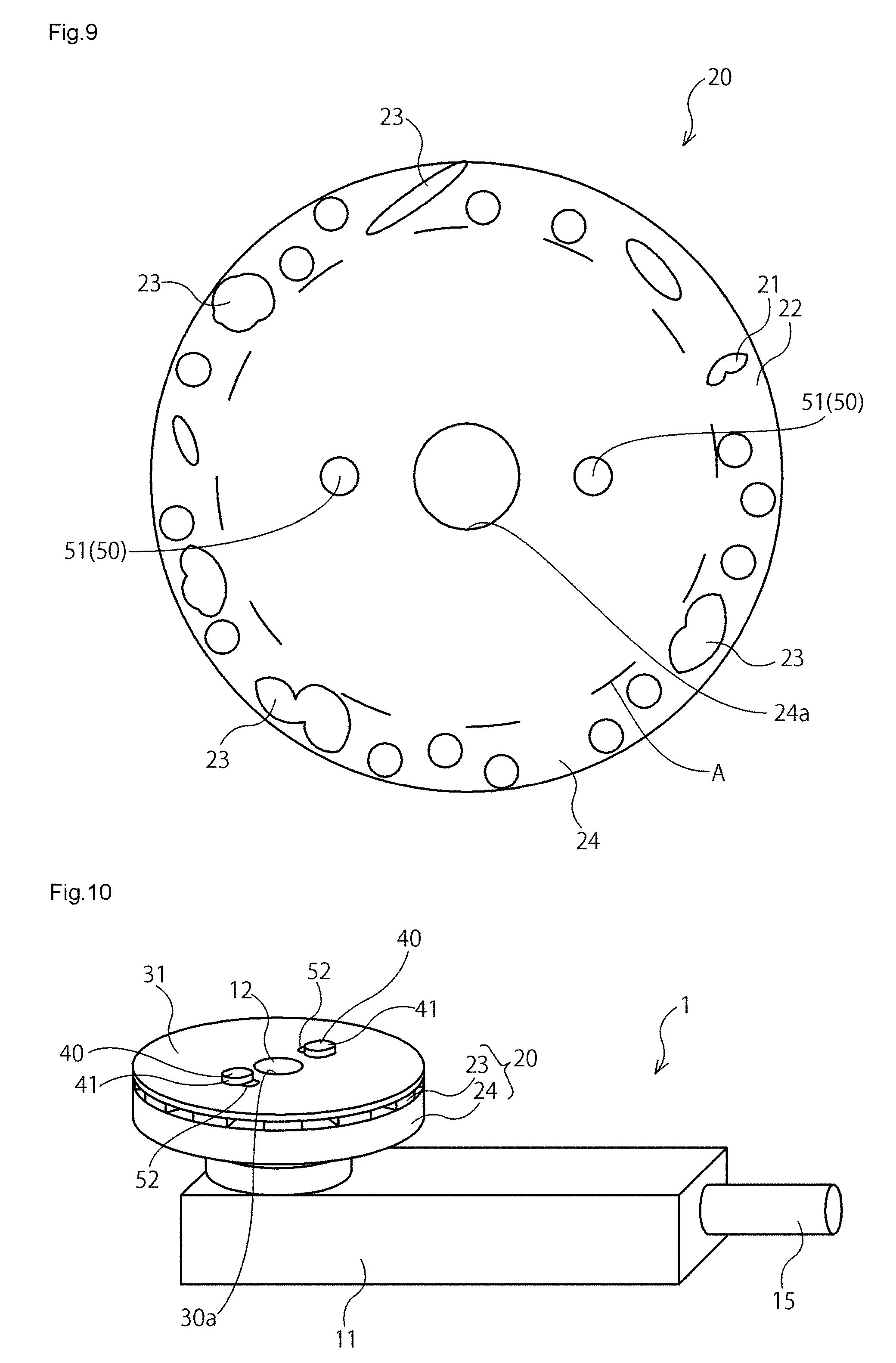
[0027] FIG. 10 is a perspective view showing a third modification of the grinding device according to the first embodiment of the present invention.
[0028] FIG. 11 is an exploded perspective view showing a grinding device according to a second embodiment of the present invention.
[0029] FIG. 12 is a perspective view showing an assembled state of the grinding device shown in FIG. 11.
[0030] FIG. 13 is a cross-sectional view taken along a line A-A in FIG. 12.
[0031] FIG. 14 is an exploded perspective view showing a grinding device according to a third embodiment of the present invention.
[0032] FIG. 15 is an exploded perspective view of the grinding device shown in FIG. 14, as viewed from the rotary drive unit side.
[0033] FIG. 16 is a vertical cross-sectional view of the grinding device shown in FIG. 14.
[0034] FIG. 17 is a perspective view showing a support unit of the grinding device shown in FIG. 14.
[0035] FIG. 18 is a vertical cross-sectional view of the support unit shown in FIG. 17, from which an inner cylindrical portion is omitted.
[0036] FIG. 19 is an exploded perspective view showing a grinding device according to a fourth embodiment of the present invention.
[0037] FIG. 20 is an exploded perspective view of the grinding device shown in FIG. 19, as viewed from the rotary drive unit side.
[0038] FIG. 21 is a vertical cross-sectional view of the grinding device shown in FIG. 19.
[0039] FIG. 22 shows schematic drawings for explaining operation of a first face gear to a third face gear of the grinding device shown in FIG. 19.
[0040] FIG. 23 shows schematic drawings for explaining operation of the first face gear to the third face gear of the grinding device shown in FIG. 19.
[0041] FIG. 24 is a front view showing a modification of protruding surface portions and recessed surface portions of the grinding device according to the present invention.
[0042] FIG. 25 is a front view showing another modification of the protruding surface portions and the recessed surface portions of the grinding device according to the present invention.
[0043] FIG. 26 is a perspective view showing a conventional grinding device.
[0044] FIG. 27(a) and FIG. 27(b) are partially enlarged schematic front views showing an area at and around the grinding element of the grinding device shown in FIG. 26; FIG. 27(a) shows an unused state of the grinding element, and FIG. 27(b) shows a used state thereof.
DESCRIPTION OF EMBODIMENTS
[0045] Hereafter, embodiments of the present invention will be described with reference to the accompanying drawings. Grinding devices 1 according to the embodiments are each a device for grinding a work W (see FIG. 4) formed of common steel, stainless steel, aluminum, plastic, or the like. Although the following will describe a free-hand grinder such as a disk grinder, to be operated by a user with the hands, the present invention is also applicable to a grinding machine that can automatically grind the work W when the work W is set thereon. In the following description, an axial direction, a circumferential direction, and a radial direction are defined on the basis of a rotary shaft 12 of the grinding device 1. In addition, the face of the grinding device 1 which makes contact with the work W is defined as a front surface, and the opposite face as a rear surface.
[0046] With reference to FIG. 1 to FIG. 3, the grinding device 1 according to a first embodiment of the present invention will be described. As shown in FIG. 1 and FIG. 2, the grinding device 1 includes: a support unit 20 which is attached to the rotary shaft 12 driven by a rotary drive unit 11, so as to be rotatable integrally with the rotary shaft 12; a grinding element 30 which is stacked on the support unit 20; and a fixing unit 40 which fixes the grinding element 30 to the support unit 20. The rotary drive unit 11 includes a built-in rotary driving source such as a motor which rotates with power supplied through a power cord 15, so that when the rotary driving source is activated the rotary shaft 12 is made to rotate. Here, a hydraulic motor or a pneumatic motor which utilizes compressed air may be used as the rotary driving source, and, for example, the rotary drive unit 11 may be composed of an air tool with a built-in pneumatic motor. Any one of the known rotary drive units 11 may be employed, provided that the drive unit is capable of driving the rotary shaft 12.
[0047] The support unit 20 includes two members, namely, a protrusion/recess-forming member 23 and a base member 24 having the protrusion/recess-forming member 23 fixed to the surface thereof. In the surface of the support unit 20, protruding surface portions 21 which make contact with the rear surface of the grinding element 30 when in use, and recessed surface portions 22 recessed from the protruding surface portions 21, are alternately formed in the circumferential direction, because of the presence of the protrusion/recess-forming member 23.
[0048] The base member 24 is formed in a disk shape having the same diameter as the grinding element 30, and has a through hole 24a formed at the center thereof for inserting the rotary shaft 12 therethrough. Two engaging projections 51 stick out parallel to the axial direction of the rotary shaft 12, from the surface of the base member 24 at positions around the through hole 24a. Here, the term "disk shape" includes not only a flat plate having no recess, but also such a shape in which, in a side view, the peripheral portion of the plate is flat while the central portion is recessed in a cup shape.
[0049] The protrusion/recess-forming member 23 includes a central portion 25 having a diameter smaller than the outer diameter of the base member 24, and a plurality of peripheral portions 26 radially extending from the central portion 25, and the central portion 25 and the peripheral portions 26 are integrally formed. The peripheral portions 26 each extend to a position corresponding to the outer edge of the base member 24. The central portion 25 has a through hole 25a formed for inserting the rotary shaft 12 therethrough. In addition, attachment holes 26a for inserting the engaging projections 51 therethrough to attach the protrusion/recess-forming member 23 to the base member 24 are formed in the peripheral portion 26 at locations where the engaging projections 51 are located when the protrusion/recess-forming member 23 is attached to the base member 24. The attachment holes 26a each have a size with a clearance which allows the engaging projection 51 to penetrate therethrough. In the protrusion/recess-forming member 23, the peripheral portions 26 form the protruding surface portions 21 and the portions between the protruding surface portions 21 adjacent to each other form the recessed surface portions 22, whereby the protruding surface portions 21 and the recessed surface portions 22 are integrally provided, and the protruding surface portions 21 and the recessed surface portion 22 recessed from the protruding surface portion 21 are alternately located in the circumferential direction. Since the peripheral portions 26 extend radially, the protrusion/recess-forming member 23 is formed such that the protruding surface portions 21 and the recessed surface portions 22 also form a radial pattern.
[0050] The protrusion/recess-forming member 23 and the base member 24 are formed of, for example, a desired material such as a metal, a resin, and rubber. As the material for forming the protrusion/recess-forming member 23 and the base member 24, a material most suitable for the materials of the grinding element 30 and the work W may be selected as appropriate. The protrusion/recess-forming member 23 and the base member 24 do not necessarily need to be formed of the same material. Employing different materials for the protrusion/recess-forming member 23 and the base member 24 allows various types of grinding elements 30 and works W to be adopted or handled, thereby improving the versatility of the grinding device 1. Further, when different materials are to be adopted for the protrusion/recess-forming member 23 and the base member 24, the material for the protrusion/recess-forming member 23 and the material for the base member 24 can be individually selected, and therefore the support unit can have flexibility depending on a combination of the protrusion/recess-forming member 23 and the base member 24.
[0051] The grinding element 30 has a disk shape, with an uneven grinding surface 31 formed by a plurality of abrasive grains. As the grinding element 30, for example, a known grindstone, a coated abrasive product such as a multiple disk and a sanding disk, or a flexible grinding material such as a non-woven abrasive fabric may be used. Here, the term "disk shape" includes not only to a flat plate having no recess, but also such a shape in which, in a side view, the peripheral portion of the plate is flat while the central portion is recessed in a cup shape.
[0052] The grinding element 30 has: a through hole 30a formed at the center thereof for inserting the rotary shaft 12 therethrough; and two engaging holes 52 formed around the through hole 30a at positions where the respective engaging projections 51 are located when the grinding element 30 is stacked on the support unit 20. Each engaging hole 52 extends in the circumferential direction, so that the engaging projection 51 is movable therein within the range corresponding to the length of the engaging hole 52. Accordingly, the grinding element 30 is configured to be displaceable in the circumferential direction about the rotary shaft 12, within the range in which the engaging projection 51 is engaged with the engaging hole 52, so as to change the relative position with respect to the support unit 20.
[0053] As shown in FIG. 3, at least one of the engaging holes 52 is formed in a shape in which three arcs 52a are connected on the outer circumferential side. Such a configuration allows the engaging projection 51 to be located so as to be fitted to each arc 52a, thereby facilitating the adjustment of the angle by which the grinding element 30 is displaced about the rotary shaft 12. The number of arcs 52a may be set to a desired value not less than two. The arcs 52a may be formed on the inner circumferential side, instead of on the outer circumferential side. Alternatively, the arcs 52a may be omitted, for example, in the case where the engaging projection 51 is positioned with respect to both ends of the engaging hole 52. The engaging projection 51 and the engaging hole 52 constitute an engagement mechanism 50 which makes an engagement at each of predetermined angular positions so as to retain the grinding element 30 moved by a predetermined angle in the circumferential direction. Furthermore, the grinding element 30 and the protrusion/recess-forming member 23 constitute a grinding implement 2 to be attached, for use, to the base member 24 which is attached to the rotary shaft 12 driven by the rotary drive unit 11 so as to be rotatable integrally with the rotary shaft 12 and which has the engaging projections 51 formed on the surface thereof.
[0054] The fixing unit 40 includes a flange portion 41 having a larger diameter than the through hole 30a of the grinding element 30, and a leg portion 42 integrally formed with the flange portion 41. The leg portion 42 is detachably engaged with the rotary shaft 12, inside the through hole 30a of the grinding element 30, the through hole 25a of the protrusion/recess-forming member 23, and the through hole 24a of the base member 24. By the engagement between the leg portion 42 and the rotary shaft 12, the grinding element 30 and the support unit 20 composed of the protrusion/recess-forming member 23 and the base member 24, are attached to the rotary shaft 12 so as to be rotatable integrally therewith. In addition, the flange portion 41 presses the grinding element 30, so that the grinding element 30 is fixed onto the support unit 20, i.e., the protrusion/recess-forming member 23. Here, the support unit 20 may be integrally attached to the rotary shaft 12, by inserting the rotary shaft 12 into the through hole 24a so as to tightly fit the rotary shaft 12 therein. Alternatively, a female thread may be formed in the through hole 24a and a male thread may be formed on the rotary shaft 12, so that the support unit 20 can be integrally attached to the rotary shaft 12 by threaded engagement between the female thread and the male thread.
[0055] In this embodiment, as described above, the protruding surface portions 21 and the recessed surface portions 22 formed by the protrusion/recess-forming member 23 are alternately located in the circumferential direction in the surface of the support unit 20, out of which only the protruding surface portions 21 are in contact with the grinding element 30. Accordingly, when the grinding element 30 grinds the work W, the pressure of the grinding element 30 against the work W concentrates only in the region where the protruding surface portions 21 are in contact with the grinding element 30 (indicated by arrows F in FIG. 4), and therefore the grinding element 30 grinds the work W in the region where the protruding surface portions 21 are in contact with the grinding element 30. On the other hand, in the region where the grinding element 30 opposes the recessed surface portions 22, the grinding element 30 is in contact with the work W but merely slides on the surface of the work W without actually grinding the work W. Therefore, in the region where the protruding surface portions 21 are in contact with the grinding element 30, the abrasive grains are evenly worn, so that the grinding surface 31, which is initially uneven, is smoothed.
[0056] However, although the grinding surface 31 is smoothed when the protruding surface portions 21 and the grinding element 30 have a first positional relationship as shown in FIG. 4(a), the grinding element 30 can be displaced in the circumferential direction about the rotary shaft 12 within the range where the engaging hole 52 is formed. Therefore, the protruding surface portions 21 and the grinding element 30 can be set to a second positional relationship as shown in FIG. 4(b), by loosening or detaching the fixing unit 40, changing the relative position of the grinding element 30 with respect to the protruding surface portion 21, i.e., the support unit 20, and again fixing the grinding element 30 by means of the fixing unit 40. In the region where the protruding surface portions 21 are in contact with the grinding element 30, in the second positional relationship, which contributes to grinding the work W, the abrasive grains are not yet worn and the grinding surface 31 is uneven, and therefore the grinding capability of the grinding element 30 can be recovered.
[0057] Furthermore, the abrasive grains are worn in different manners, between the first positional relationship and the second positional relationship of the protruding surface portions 21 and the grinding element 30. In addition, in the case of attempting to reset the positional relationship between the protruding surface portions 21 and the grinding element 30 to the first positional relationship, it is practically impossible to accurately reset the positional relationship to the first positional relationship in a strict sense, and the positional relationship is surely shifted therefrom. Therefore, when the grinding capability has declined in the second positional relationship between the protruding surface portions 21 and the grinding element 30, projections and recesses are formed on the grinding surface 31 by resetting the protruding surface portions 21 and the grinding element 20 to the first positional relationship, and grinding can be resumed using such projections and recesses. Changing the position of the grinding element 30 with respect to the protruding surface portions 21 each time the grinding capability begins to decline suppresses a drastic decline in grinding capability, thereby preventing an increase in friction due to the decline in grinding capability, thus preventing a grinding burn.
[0058] In this embodiment, moreover, the support unit 20 is provided with the engaging projections 51, and the grinding element 30 has the engaging holes 52 extending in the circumferential direction. Such a configuration allows the grinding element 30 to change the relative position with respect to the support unit 20 to each predetermined angular position, within the range where the engaging hole 52 is formed, so that the region of the grinding element 30 where the grinding surface 31 is uneven can be assuredly brought into contact with the protruding surface portions 21. Furthermore, since the protruding surface portions 21 and the recessed surface portions 22 are formed in the radial pattern in the surface of the support unit 20, the protruding surface portions 21 and the recessed surface portions 22 can have increased areas, so that the protruding surface portions 21 are prevented from chipping from the surface of the support unit 20, which leads to enhanced safety of the grinding device 1.
[0059] The first embodiment may be modified as follows. FIG. 5 illustrates a first modification of the first embodiment of the present invention. As shown in FIG. 5, each engaging hole 52 of the grinding element 30 may be formed in a circular shape having a size which allows the engaging projection 51 to be engaged with or disengaged from the engaging hole 52, and a plurality of the engaging holes 52, six in this modification, may be formed at predetermined angular positions in the circumferential direction, respectively, and at the positions in the radial direction where the engaging holes 52 can be engaged with the respective engaging projections 51. In addition, the protrusion/recess-forming member 23 may include a flat plate portion 27 provided on the rear surface of the central portion 25, and the plurality of peripheral portions 26 radially extending from the central portion 25. In this modification also, the grinding element 30 and the protrusion/recess-forming member 23 constitute the grinding implement 2 to be attached, for use, to the base member 24 which is attached to the rotary shaft 12 driven by the rotary drive unit 11, so as to be rotatable integrally with the rotary shaft 12 and which has the engaging projections 51 on the surface thereof.
[0060] The form of the protrusion/recess-forming member 23, i.e., the protruding surface portions 21 and the recessed surface portions 22, is not limited to the form in which the protruding surface portions 21 and the recessed surface portions 22 are formed linearly and radially as shown in FIG. 2 and FIG. 5, but may be a form in which the peripheral portions 26 extend from the central portion 25 in a curved shape like a windmill as shown in FIG. 6. In this case also, the peripheral portions 26 of the protrusion/recess-forming member 23 may form the protruding surface portions 21, and the portions between the peripheral portions 26 adjacent to each other may form the recessed surface portions 22.
[0061] Furthermore, although the support unit 20 is composed of the protrusion/recess-forming member 23 and the base member 24, which are independently formed, in the first embodiment, the support unit 20 may be formed so as to integrally include the protruding surface portions 21 and the recessed surface portions 22, as a second modification of the first embodiment shown in FIG. 7. More specifically, the support unit 20 may be formed by fixing a plurality of protrusion/recess-forming members 23 in the surface of the base member 24 at predetermined intervals in the circumferential direction. In this case, the surface of each protrusion/recess-forming member 23 constitutes the protruding surface portion 21, and the surface of the base member 24 where each protrusion/recess-forming member 23 is not provided constitutes the recessed surface portion 22. Normally, only a predetermined region A in the peripheral portion of the grinding surface 31 (see FIG. 3) of the grinding element 30 is used for the grinding operation, and therefore, in this embodiment, the protrusion/recess-forming members 23 are provided over a location corresponding to the region A when the grinding element 30 is stacked on the support unit 20. Here, the protrusion/recess-forming members 23 may be located in the radial pattern as shown in FIG. 2 and FIG. 6, in which case the support unit 20 is formed such that the protruding surface portions 21 and the recessed surface portions 22 are formed in the radial pattern. Alternatively, the support unit 20 may be formed by integrally molding the protrusion/recess-forming members 23 and the base member 24.
[0062] Forming the support unit 20 so as to integrally include the protruding surface portions 21 and the recessed surface portions 22 allows the protruding surface portions 21 and the recessed surface portions 22 to gain flexibility as part of the support unit 20. Therefore, for example, when the grinding device 1 is used to grind a curved portion, the support unit 20 assumes a shape that fits the curved portion, and the work W can be processed more quickly and cleanly.
[0063] The form of the protruding surface portions 21 and the recessed surface portions 22 is not limited to the form in which the protruding surface portions 21 and the recessed surface portions 22 are located at predetermined intervals in the circumferential direction as shown in FIG. 7. For example, the protrusion/recess-forming members 23 shown in FIG. 7 may be formed in the region A in a circular shape, an elliptical shape, or any other desired shape as shown in FIG. 8 or FIG. 9, so that the surface of each protrusion/recess-forming member 23 constitutes the protruding surface portion 21 and the surface of the base member 24 where each protrusion/recess-forming member 23 is not provided constitutes the recessed surface portion 22.
[0064] Although the fixing unit 40 is provided to the rotary shaft 12 in the first embodiment, for example, no fixing unit may be provided to the rotary shaft 12 and the fixing unit 40 may be provided to each engaging projection 51 as in a third modification of the first embodiment shown in FIG. 10. Accordingly, the engaging projections 51 engaged with the engaging holes 52 can be moved in the circumferential direction along the engaging holes 52 so as to set the grinding element 30 in position with respect to the support unit 20, and the grinding element 30 can be fixed to the support unit 20 by means of the fixing unit 40 with the relative position of the grinding element 30 with respect to the support unit 20 shifted. As result, the structure of the grinding device 1 can be simplified.
[0065] Although the fixing unit 40 includes the flange portion 41 and the leg portion 42 in the first embodiment, the configuration of the fixing unit 40 is not limited to the above configuration. For example, a hook-and-loop fastener may be attached to the rear surface of the grinding element 30 (opposite to the grinding surface 31), and also to the protruding surface portions 21, thereby constituting the fixing unit 40. Alternatively, an adhesive capable of bonding the rear surface of the grinding element 30 and the protruding surface portions 21 to such a degree which allows separation therebetween, may be employed as the fixing unit 40.
[0066] Furthermore, although the support unit 20 is provided with the engaging projections 51 and the grinding element 30 has the engaging holes 52 in the first embodiment and the modifications thereof, the engaging holes 52 may be provided in the support unit 20, and the engaging projections 51 may be provided to the grinding element 30. Although the two engaging projections 51 are provided and also the two engaging holes 52 are provided so as to correspond to the respective engaging projections 51 in the first embodiment and the modifications thereof, the number of engaging projections 51 is not limited to two, but may be one, or three or more, provided that the grinding element 30 is relatively movable with respect to the support unit 20. In this case, the engaging holes 52 are provided so as to correspond to the engaging projections 51.
[0067] Next, with reference to FIG. 11 to FIG. 13, the grinding device 1 according to a second embodiment of the present invention will be described. As shown in FIG. 11, the grinding device 1 includes: the support unit 20 which is attached to the rotary shaft 12 driven by the rotary drive unit 11, so as to be rotatable integrally with the rotary shaft 12; the grinding element 30 which is stacked on the support unit 20; and the fixing unit 40 which fixes the grinding element 30 to the support unit 20. The rotary drive unit 11 has the same configuration as in the first embodiment, and therefore the same components are designated by the same reference numerals and the detailed description thereof is omitted.
[0068] The support unit 20 includes the base member 24, and the protrusion/recess-forming member 23 integrally formed on the base member 24. The base member 24 has a circular shape, in a plan view, having the same diameter as the grinding element 30, and is formed such that, in a side view, the peripheral portion is flat while the central portion is recessed in a cup shape. At the center of the base member 24 (deepest position of the cup-shaped portion), the through hole 24a for inserting the rotary shaft 12 therethrough is formed.
[0069] The protrusion/recess-forming member 23 has a generally rectangular shape having a length generally equal to the length of the flat peripheral portion of the base member 24 in the radial direction. A plurality of such protrusion/recess-forming members 23 are integrally formed on the flat peripheral portion of the base member 24 at predetermined intervals in the circumferential direction. In the surface of the support unit 20, the protruding surface portions 21 which make contact with the rear surface of the grinding element 30 when in use, and the recessed surface portions 22 recessed from the protruding surface portions 21, are alternately formed in the circumferential direction, because of the presence of the protrusion/recess-forming members 23.
[0070] The support unit 20 is formed of, for example, a desired material such as a metal, a resin, and rubber. As the material for forming the support unit 20, a material most suitable for the materials of the grinding element 30 and the work W may be selected as appropriate.
[0071] The grinding element 30 has a circular shape in a plan view, and is formed such that, in a side view, the peripheral portion is flat while the central portion is recessed in a cup shape. The grinding element 30 includes the uneven grinding surface 31 formed by the plurality of abrasive grains, located on the surface of the peripheral portion which is flat in a side view. As the grinding element 30, for example, a known grindstone, a coated abrasive product such as a multiple disk and a sanding disk, or a flexible grinding material such as a non-woven abrasive fabric may be used.
[0072] As shown in FIG. 11 to FIG. 13, the grinding element 30 has the through hole 30a formed at the center thereof, and a ratchet gear 61 is attached to the inner circumference of the through hole 30a. The ratchet gear 61 is formed as an internal gear having a predetermined pitch in the circumferential direction, and includes two flange portions 61a extending outward in the radial direction. Although the details are not illustrated in FIG. 11 to FIG. 13, one of the two flange portions 61a is integrally formed with the ratchet gear 61, and the other is formed independently of the ratchet gear. The ratchet gear 61 is attached to the grinding element 30 by holding the portion of the grinding element 30 around the through hole 30a between the two flange portions 61a and fastening the flange portions 61a together with the mentioned portion of the grinding element 30 by means of a screw, a clamp, or the like (not shown). In addition, a bottom portion 61b is provided on the support unit 20 side of the ratchet gear 61 so as to protrude inwardly with respect to the tip portion of the ratchet gear 61.
[0073] The fixing unit 40 includes: the flange portion 41 having a size which allows the flange portion 41 to fit into the ratchet gear 61; and the leg portion 42 integrally formed with the flange portion 41. A female thread (not shown) is formed on the inner circumferential surface of the leg portion 42, and the fixing unit 40 is attached to the rotary shaft 12 by threadedly engaging the female thread with a male thread (not shown) formed on the outer circumferential surface of the rotary shaft 12. When the leg portion 42 is engaged with the rotary shaft 12, the flange portion 41 presses the bottom portion 61b of the ratchet gear 61, so that the grinding element 30 is fixed onto the support unit 20. At this time, the grinding element 30 is fixed to the support unit 20 to such a degree which allows the grinding element 30 to move in the circumferential direction. In addition, a male thread (not shown) is formed on the outer circumferential surface of the leg portion 42, and the base member 24, i.e., the support unit 20, is attached to the fixing unit 40, i.e., the rotary shaft 12, so as to be rotatable integrally therewith by threadedly engaging the male thread on the outer circumferential surface of the leg portion 42 with a female thread (not shown) formed on the inner circumferential surface of the through hole 24a of the base member 24.
[0074] Four recessed surface portions 43 are formed in the outer circumferential surface 41a of the flange portion 41 of the fixing unit 40, and a ratchet pawl 62 is attached in each of the recessed surface portions 43 with a spring 63 interposed therein. In other words, the ratchet pawl 62 is attached, via the fixing unit 40, to the rotary shaft 12 with which the fixing unit 40 is threadedly engaged. The tip portion of the ratchet pawl 62 is formed so as to be engageable with the pitch of the ratchet gear 61. The ratchet gear 61 and the ratchet pawls 62 constitute an engagement mechanism 60 which makes an engagement at each of predetermined angular positions. Since the engagement mechanism 60 is a ratchet mechanism, the grinding element 30 which engages with the fixing unit 40, i.e., the rotary shaft 12, via the engagement mechanism 60, can be made to rotate in one direction (the direction of an arrow B in FIG. 12). By rotating the grinding element 30 by an angle corresponding to one pitch of the ratchet gear 61, the grinding element 30 can be retained by means of the engagement mechanism 60 in a state where the grinding element 30 has been moved by a predetermined angle in the circumferential direction. Here, the number of ratchet pawls 62 is not limited to four, but may be any number not less than one.
[0075] In this embodiment, the grinding element 30 and the fixing unit 40 having the engagement mechanism 60 constitute a grinding implement 3 to be attached, for use, to the support unit 20 which is attached to the rotary shaft 12 driven by the rotary drive unit 11, so as to be rotatable integrally with the rotary shaft 12 and which has in the surface thereof the protruding surface portions 21 and the recessed surface portions 22 recessed from the protruding surface portions 21 alternately located in the circumferential direction.
[0076] In this embodiment as well, as described above, the protruding surface portions 21 and the recessed surface portions 22 formed by the protrusion/recess-forming members 23 are alternately located in the circumferential direction in the surface of the support unit 20, out of which only the protruding surface portions 21 are in contact with the grinding element 30. By rotating the grinding element 30 in the direction of the arrow B in FIG. 12, the relative position of the grinding element 30 with respect to the support unit 20 can be changed with the engagement mechanism 60, so that the region where the protruding surface portions 21 are in contact with the grinding element 30 can be changed. Accordingly, similar to the first embodiment, changing the position of the grinding element 30 with respect to the protruding surface portions 21 each time the grinding capability begins to decline suppresses a drastic decline in grinding capability, thereby preventing an increase in friction due to the decline in grinding capability, thus preventing a grinding burn.
[0077] In this embodiment as well, moreover, the relative position of the grinding element 30 with respect to the support unit 20 can be changed to each predetermined angular position, so that the region of the grinding element 30 where the grinding surface 31 is uneven can be assuredly brought into contact with the protruding surface portions 21, as in the first embodiment.
[0078] The second embodiment may be modified as follows. Although the ratchet gear 61 is attached to the grinding element 30 and the ratchet pawl 62 is attached to the rotary shaft 12 via the fixing unit 40 in the second embodiment, the ratchet gear 61 may be attached to the support unit 20, and the ratchet pawl 62 may be attached directly to the rotary shaft 12, for example. In this case, the engagement mechanism 60 is provided between the support unit 20 and the rotary shaft 12, and the support unit 20 is relatively movable with respect to the grinding element 30.
[0079] Next, with reference to FIG. 14 to FIG. 18, the grinding device 1 according to a third embodiment of the present invention will be described. As shown in FIG. 14 and FIG. 15, the grinding device 1 includes: the support unit 20 which is attached to the rotary shaft 12 driven by the rotary drive unit 11, so as to be rotatable integrally with the rotary shaft 12; the grinding element 30 which is stacked on the support unit 20; and the fixing unit 40 which fixes the grinding element 30 to the support unit 20. The rotary drive unit 11 has the same configuration as in the first embodiment, and therefore the same components are designated by the same reference numerals and the detailed description thereof is omitted.
[0080] The grinding element 30 has a circular shape in a plan view, and is formed such that, in a side view, the peripheral portion is flat while the central portion is slightly recessed. The grinding element 30 has the uneven grinding surface 31 formed by the plurality of abrasive grains, located on the surface of the peripheral portion which is flat in a side view. As the grinding element 30, for example, a known grindstone, a coated abrasive product such as a multiple disk and a sanding disk, or a flexible grinding material such as a non-woven abrasive fabric may be used.
[0081] The grinding element 30 has the through hole 30a formed at the center thereof for inserting the rotary shaft 12 therethrough. A guide member 76 is attached to the rear surface of the grinding element 30, at the position around the through hole 30a. The guide member 76 has a cylindrical shape, and protruding surface portions 76a and recessed surface portions 76b extending in the axial direction are formed on the outer circumferential surface of the guide member 76, so as to be alternately arranged in the circumferential direction. The guide member 76 is attached to the grinding element 30 by means of an adhesive, a clamp, a screw, or the like. The grinding element 30 and the guide member 76 constitute a grinding implement 4 to be attached, for use, to the support unit 20 which is attached to the rotary shaft 12 driven by the rotary drive unit 11, so as to be rotatable integrally with the rotary shaft 12 and which has in the surface thereof the protruding surface portions 21 and the recessed surface portions 22 recessed from the protruding surface portions 21 alternately located in the circumferential direction.
[0082] As shown in FIG. 14 to FIG. 16, a displacement member 77 is attached to the outer circumference of the guide member 76 so as to be movable in the axial direction along the guide member 76 but be restricted from moving in the circumferential direction. More specifically, the displacement member 77 has, in the inner circumferential surface thereof, protruding surface portions 77a and recessed surface portions 77b to be respectively engaged with the recessed surface portions 76b and the protruding surface portions 76a formed in the outer circumferential surface of the guide member 76, and the protruding surface portions 77a and the recessed surface portions 77b are alternately formed in the circumferential direction. The protruding surface portions 77a of the displacement member 77 are engaged with the recessed surface portions 76b of the guide member 76, and the recessed surface portions 77b of the displacement member 77 are engaged with the protruding surface portions 76a of the guide member 76, so that the displacement member 77 is attached to the guide member 76 so as to be movable in the axial direction but be restricted from moving in the circumferential direction. The guide member 76 and the displacement member 77 constitute a displacement mechanism 75.
[0083] The displacement member 77 includes engaging pins 71 projecting outward in the radial direction from the outer circumferential surface thereof. It suffices that at least one engaging pin 71 is provided, and four engaging pins 71 are provided in this embodiment, at predetermined intervals in the circumferential direction.
[0084] The support unit 20 includes the base member 24, and the protrusion/recess-forming member 23 integrally formed on the base member 24. The base member 24 has a circular shape having the same diameter as the grinding element 30 in a plan view, and includes a flat plate-shaped portion 24b formed in the peripheral portion, a bottomed outer cylindrical portion 24c provided in the central region of the plate-shaped portion 24b so as to axially extend toward the rear side, and an inner cylindrical portion 24d provided inside the outer cylindrical portion 24c so as to extend from the bottom of the outer cylindrical portion 24c toward the front side. The outer cylindrical portion 24c has a hole which is formed in the bottom thereof and communicates with the inner circumferential surface of the inner cylindrical portion 24d, and a hole defined by the inner circumferential surface of this hole and the inner circumferential surface of the inner cylindrical portion 24d constitutes the through hole 24a through which the rotary shaft 12 can be inserted. A female thread (not shown) is formed in the through hole 24a, so that the support unit 20 can be attached to the rotary shaft 12 by threaded engagement between the female thread and the male thread (not shown) formed on the rotary shaft 12.
[0085] The protrusion/recess-forming member 23 has a generally rectangular shape having a length generally equal to the length of the plate-shaped portion 24b of the base member 24 in the radial direction. A plurality of such protrusion/recess-forming members 23 are integrally formed on the plate-shaped portion 24b of the base member 24 at predetermined intervals in the circumferential direction. In the surface of the support unit 20, the protruding surface portions 21 which make contact with the rear surface of the grinding element 30 when in use, and the recessed surface portions 22 recessed from the protruding surface portions 21 are alternately formed in the circumferential direction, because of the presence of the protrusion/recess-forming members 23.
[0086] As shown in FIG. 17 and FIG. 18, the base member 24 has an engaging groove 72 formed on the inner circumferential surface of the outer cylindrical portion 24c throughout the entirety of the inner circumference thereof, and the engaging groove 72 has a width which allows insertion of the engaging pin 71 thereinto. The engaging groove 72 has a plurality of first grooves 72a axially extending at respective predetermined angular positions, and a plurality of second grooves 72b connecting between the upper and the lower end of the first grooves 72a located adjacent to each other. More specifically, the second grooves 72b are shaped so as to be inclined downward in the direction opposite to the rotation direction of the support unit 20 (the direction of an arrow C in FIG. 17 and FIG. 18). Here, the upward and downward directions are defined on the basis of the up-down direction in FIG. 17 and FIG. 18, the grinding element 30 side is defined as the upper side, and the bottom side of the outer cylindrical portion 24c is defined as the lower side. A sidewall which is located at the lower end portion of the first groove 72a and where the first groove 72a and the second groove 72b are connected to each other, constitutes a stepped portion 72c which is to be engaged with the engaging pin 71 when the grinding device 1 is in use. Since the first groove 72a is formed at each of the predetermined angular positions, a plurality of the stepped portions 72c are also provided in the engaging groove 72 at the respective angular positions. In the case where a plurality of engaging pins 71 are provided, all of the engaging pins 71 are provided in the displacement member 77 so as to be engageable with the stepped portion 72c at each of the predetermined angular positions. The engaging pin 71 and the engaging groove 72 constitute an engagement mechanism 70 which makes an engagement at each of the predetermined angular positions so as to retain the grinding element 30 moved by a predetermined angle in the circumferential direction.
[0087] The support unit 20 is formed of, for example, a desired material such as a metal, a resin, and rubber. As the material for forming the support unit 20, a material most suitable for the materials of the grinding element 30 and the work W may be selected as appropriate.
[0088] The fixing unit 40 includes the flange portion 41 having a larger diameter than the through hole 30a of the grinding element 30, and the leg portion 42 integrally formed with the flange portion 41. A male thread (not shown) is formed on the outer circumferential surface of the leg portion 42.
[0089] As shown in FIG. 16, the displacement member 77 is attached between the outer cylindrical portion 24c and the inner cylindrical portion 24d of the support unit 20 attached to the rotary shaft 12. More specifically, the engaging pin 71 attached to the outer circumference of the displacement member 77 is detachable by means of the screw. Accordingly, by positioning the displacement member 77 between the outer cylindrical portion 24c and the inner cylindrical portion 24d and attaching the engaging pin 71 to the displacement member 77 via a screw hole (not shown) provided in the outer cylindrical portion 24c, the displacement member 77 is attached to the support unit 20, with the engaging pin 71 fitted in the engaging groove 72 formed in the outer cylindrical portion 24c. In this state, a spring 78 which biases the displacement member 77 toward the grinding element 30 is provided between the bottom of the outer cylindrical portion 24c and the displacement member 77. The spring 78 has a biasing force smaller than a torque generated when the grinding element 30 described below contacts the work W.
[0090] The grinding element 30 is attached to the support unit 20 by inserting the guide member 76 into the inner circumference of the displacement member 77. By threadedly engaging the male thread on the leg portion 42 of the fixing unit 40 with a female thread (not shown) of the support unit 20, the flange portion 41 of the fixing unit 40 is caught by the portion of the grinding element 30 around the through hole 30a, so that the grinding element 30 is fixed onto the support unit 20. At this time, the grinding element 30 is fixed to the support unit 20 to such a degree which allows the grinding element 30 to move in the circumferential direction.
[0091] Next, with reference to FIG. 17 and FIG. 18, the working of the engagement mechanism 70 and the displacement mechanism 75 to relatively move the grinding element 30 in the circumferential direction with respect to the support unit 20, will be described. Since the support unit 20 is threadedly engaged with the rotary shaft 12, the support unit 20 is made to rotate in the direction of the arrow C when the rotary shaft 12 is driven by the rotary drive unit 11. When the grinding device 1 is used, the grinding element 30 is pressed against the work W, and the grinding element 30 is subjected to a torque generated owing to the friction with the work W and imposed in the direction opposite to the rotation direction of the support unit 20 (the direction of the arrow C). The torque is transmitted, via the guide member 76 integrally attached to the grinding element 30, to the displacement member 77 attached to the guide member 76 so as to be restricted from moving in the circumferential direction. The torque generated at this time is greater than the biasing force of the spring 78 biasing the displacement member 77 toward the grinding element 30, and therefore the engaging pin 71 attached to the displacement member 77 is moved toward the bottom side of the outer cylindrical portion 24c, against the biasing force of the spring 78. Therefore, the engaging pin 71 migrates inside the engaging groove 72 toward the bottom side of the outer cylindrical portion 24c, and in the direction in which the torque is generated, that is, in the direction of an arrow D1 in FIG. 18, and comes into engagement with the stepped portion 72c.
[0092] Since the torque is generated in the direction opposite to the rotation direction of the support unit 20 (the direction of the arrow C) while the grinding element 30 is pressed against the work W, the engaging pin 71 engaged with the stepped portion 72c is retained as it is, by the torque. Accordingly, the rotation of the support unit 20 is transmitted via the stepped portion 72c and the engaging pin 71 to the displacement member 77. Since the protruding surface portions 77a and the recessed surface portions 77b of the displacement member 77 are respectively engaged with the recessed surface portions 76b and the protruding surface portions 76a of the guide member 76, the rotation of the displacement member 77 is transmitted to the guide member 76, and to the grinding element 30 integrally attached to the guide member 76, via the guide member 76. Thus, the grinding element 30 grinds the work W.
[0093] When the grinding operation for the work W is finished and the grinding element 30 is separated from the work W, the grinding element 30 is no longer subjected to the torque, and the displacement member 77 is biased toward the grinding element 30 by the biasing force of the spring 78. Accordingly, the engaging pin 71 migrates inside the engaging groove 72 in the direction of an arrow E1. At this time, the engaging pin 71 remains in contact with an upper wall surface 72d of the first groove 72a, because of the biasing force of the spring 78. When the grinding element 30 is again pressed against the work W, the grinding element 30 is subjected to a torque as described above, and the engaging pin 71 migrates inside the engaging groove 72 in the direction of an arrow D2. Since the displacement member 77 having the engaging pin 71 attached thereto and the guide member 76 attached to the grinding element 30 are unable to move in the circumferential direction, the grinding element 30 moves in the circumferential direction by a predetermined angle with respect to the support unit 20, owing to the migration of the engaging pin 71 inside the engaging groove 72 in the circumferential direction, i.e., the engaging action of the engagement mechanism 70.
[0094] As described above, in this embodiment as well, the protruding surface portions 21 and the recessed surface portions 22 formed by the protrusion/recess-forming member 23 are alternately located in the circumferential direction in the surface of the support unit 20, out of which only the protruding surface portions 21 are in contact with the grinding element 30. The relative position of the grinding element 30 with respect to the support unit 20 can be changed with the engagement mechanism 70 and the displacement mechanism 75, so that the region where the protruding surface portions 21 are in contact with the grinding element 30 can be changed. Accordingly, similar to the first embodiment, periodically changing the position of the grinding element 30 with respect to the protruding surface portions 21 suppresses a drastic decline in grinding capability, thereby preventing an increase in friction due to the decline in grinding capability, thus preventing a grinding burn.
[0095] Furthermore, in this embodiment as well, similar to the first embodiment, the relative position of the grinding element 30 with respect to the support unit 20 can be changed to each of the predetermined angular positions, so that the region of the grinding element 30 where the grinding surface 31 is uneven can be assuredly brought into contact with the protruding surface portions 21. In this embodiment, in addition, since the grinding device 1 includes the displacement mechanism 75, the grinding element 30 can be automatically moved relative to the support unit 20, without the need for the user of the grinding device 1 to intentionally move the grinding element 30 relative to the support unit 20. Therefore, the user can continue to use the grinding device 1 for a long time, without worrying about a decline in grinding capability.
[0096] The third embodiment may be modified as follows. In the third embodiment, the guide member 76 is attached to the grinding element 30, the displacement member 77 is attached via the guide member 76, and the engaging pin 71 is further attached via the displacement member 77, and also the engaging groove 72 is formed in the support unit 20. However, the engaging groove 72 may be formed in the grinding element 30, and the guide member 76, the displacement member 77, and the engaging pin 71 may be attached to the support unit 20.
[0097] Next, with reference to FIG. 19 to FIG. 21, the grinding device 1 according to a fourth embodiment of the present invention will be described. As shown in FIG. 19 and FIG. 20, the grinding device 1 includes: the support unit 20 which is attached to the rotary shaft 12 driven by the rotary drive unit 11, so as to be rotatable integrally with the rotary shaft 12; the grinding element 30 which is stacked on the support unit 20; and the fixing unit 40 which fixes the grinding element 30 to the support unit 20. The rotary drive unit 11 has the same configuration as in the first embodiment, and therefore the same components are designated by the same reference numerals and the detailed description thereof is omitted.
[0098] The support unit 20 includes the base member 24, and the protrusion/recess-forming member 23 integrally formed on the base member 24. The base member 24 has a circular shape, in a plan view, having the same diameter as the grinding element 30, and is formed such that, in a side view, the peripheral portion is flat while the central portion is recessed in a cup shape. At the center of the base member 24 (deepest position of the cup-shaped portion), the through hole 24a for inserting the rotary shaft 12 therethrough is formed, and the portion around the through hole 24a is formed as a flat bottom portion 24e.
[0099] The protrusion/recess-forming member 23 has a generally rectangular shape having a length generally equal to the length of the flat peripheral portion of the base member 24 in the radial direction. A plurality of such protrusion/recess-forming members 23 are integrally formed on the flat peripheral portion of the base member 24 at predetermined intervals in the circumferential direction. In the surface of the support unit 20, the protruding surface portions 21 which make contact with the rear surface of the grinding element 30 when in use, and the recessed surface portions 22 recessed from the protruding surface portions 21, are alternately formed in the circumferential direction, because of the presence of the protrusion/recess-forming members 23.
[0100] The support unit 20 is formed of, for example, a desired material such as a metal, a resin, and rubber. As the material for forming the support unit 20, a material most suitable for the materials of the grinding element 30 and the work W may be selected as appropriate.
[0101] The grinding element 30 has a circular shape in a plan view, and is formed such that, in a side view, the peripheral portion is flat while the central portion is recessed in a cup shape. The grinding element 30 has the uneven grinding surface 31 formed by the plurality of abrasive grains, located on the surface of the peripheral portion which is flat in a side view. As the grinding element 30, for example, a known grindstone, a coated abrasive product such as a multiple disk and a sanding disk, or a flexible grinding material such as a non-woven abrasive fabric may be used.
[0102] As shown in FIG. 19 to FIG. 21, the grinding element 30 has the through hole 30a formed at the center thereof, and a first face gear 81 is attached to the through hole 30a. The first face gear 81 has a predetermined pitch in the circumferential direction. Two flange portions 81a are formed so as to extend outward in the radial direction from the surface of the first face gear 81 opposite to the surface on which the teeth of the first face gear 81 are formed. Although the details are not illustrated in FIG. 19 to FIG. 21, one of the two flange portions 81a is integrally formed with the first face gear 81, and the other is formed independently of the first face gear 81. The first face gear 81 is attached to the grinding element 30 by holding the portion of the grinding element 30 around the through hole 30a between the two flange portions 81a and fastening the flange portions 81a together with the mentioned portion of the grinding element 30 by means of a screw, a clamp, or the like (not shown). The grinding element 30 and the first face gear 81 constitute a grinding implement 5 to be attached, for use, to the support unit 20 which is attached to the rotary shaft 12 driven by the rotary drive unit 11, so as to be rotatable integrally with the rotary shaft 12 and which has in the surface thereof the protruding surface portions 21 and the recessed surface portions 22 recessed from the protruding surface portions alternately located in the circumferential direction.
[0103] On the bottom portion 24e of the base member 24 of the support unit 20, a second face gear 82 is provided around the through hole 24a. The second face gear 82 is provided on the support unit 20, by being integrally formed with the base member 24, or being attached to the base member 24 with an adhesive, a screw, a clamp, or the like. The second face gear 82 has a pitch which allows the second face gear 82 to mesh with the first face gear 81, in the circumferential direction. The size of the second face gear 82 in the radial direction is approximately half the size of the first face gear 81 in the radial direction, and the second face gear 82 is configured to mesh with the inner portion of the first face gear 81. The first face gear 81 and the second face gear 82 constitute an engagement mechanism 80 which makes an engagement at each of predetermined angular positions so as to retain the grinding element 30 moved by a predetermined angle in the circumferential direction.
[0104] A third face gear 86 is attached to the outer circumference of the second face gear 82 so as to be movable in the axial direction but be restricted from moving in the circumferential direction. The third face gear 86 has a pitch which allows the third face gear 86 to mesh with the first face gear 81, in the circumferential direction. In addition, the third face gear 86 has an inner diameter which allows the second face gear 82 to be fitted therein, and an outer diameter generally equal to that of the first face gear 81. Thus, the third face gear 86 is configured to mesh with the outer portion of the first face gear 81.
[0105] Legs 87 extending in the axial direction are provided on the surface of the third face gear 86 opposite to the surface on which the teeth of the third face gear 86 are formed. The legs 87 each have a size which allows the leg 87 to fit into a hole 24f formed in the bottom portion 24e of the base member 24. The third face gear 86 is attached to the base member 24 of the support unit 20 by fitting the second face gear 82 to the inner circumferential surface of the third face gear 86 and inserting the legs 87 to the respective holes 24f in the bottom portion 24e of the base member 24. In this state, a spring 88 which biases the third face gear 86 toward the grinding element 30 is provided between the third face gear 86 and the bottom portion 24e. The spring 88 has such a biasing force that prevents the legs 87 of the third face gear 86 from coming out of the holes 24f. Since the legs 87 are prevented from coming out of escaping from the hole 24f, the third face gear 86 is restricted from moving in the circumferential direction with respect to the second face gear 82.
[0106] In addition, the third face gear 86 is configured such that: the tip portion of the teeth is located on the bottom portion 24e side with respect to the tip portion of the teeth of the second face gear 82, when the legs 87 are fitted in the holes 24f, i.e., when the third face gear 86 reaches a farthest position toward the bottom portion 24e of the support unit 20; and the tip portion of the teeth is located on the grinding element 30 side with respect to the tip portion of the teeth of the second face gear 82, when the third face gear 86 reaches a farthest position toward the grinding element 30 owing to the biasing force of the spring 88. Furthermore, the third face gear 86 is attached such that the position of the teeth is deviated in the circumferential direction, with respect to the second face gear 82. The third face gear 86 constitutes a displacement mechanism 85.
[0107] The fixing unit 40 includes the flange portion 41 having a diameter larger than the inner diameter of the first face gear 81, and the leg portion 42 integrally formed with the flange portion 41. A female thread (not shown) is formed on the inner circumferential surface of the leg portion 42, and the fixing unit 40 is attached to the rotary shaft 12 by threadedly engaging the female thread with a male thread (not shown) formed on the outer circumferential surface of the rotary shaft 12. When the leg portion 42 is engaged with the rotary shaft 12, the flange portion 41 can make contact with the first face gear 81, so that the grinding element 30 is retained on the support unit 20 so as to be restricted from being detached therefrom. At this time, the grinding element 30 is movable both in the axial direction and in the circumferential direction. In addition, a male thread (not shown) is formed on the outer circumferential surface of the leg portion 42, and the base member 24, i.e., the support unit 20, is attached to the fixing unit 40, i.e., the rotary shaft 12, so as to be rotatable integrally therewith by threadedly engaging the male thread on the outer circumferential surface of the leg portion 42 with a female thread (not shown) formed on the inner circumferential surface of the through hole 24a of the base member 24.
[0108] Next, with reference to FIG. 22 and FIG. 23, the working of the engagement mechanism 80 and the displacement mechanism 85 to relatively move the grinding element 30 in the circumferential direction with respect to the support unit 20, will be described. FIG. 22 and FIG. 23 are schematic drawings for explaining the operation of the first face gear 81 to the third face gear 86 of the grinding device 1 according to this embodiment. The first face gear 81, the second face gear 82, and the third face gear 86 operate in the order of FIG. 22(a), FIG. 22(b), FIG. 22(c), FIG. 23(a), FIG. 23(b), and FIG. 23(c), so that the meshing position between the first face gear 81 and the second face gear 82 is shifted in the circumferential direction. The details are as follows.
[0109] Since the support unit 20 is attached to the rotary shaft 12 via the fixing unit 40 so as to be rotatable integrally with the rotary shaft 12, the support unit 20 is made to rotate when the rotary shaft 12 is driven by the rotary drive unit 11. When the grinding device 1 is used, the grinding element 30 is pressed against the work W, and the third face gear 86 is moved toward the bottom portion 24e (toward the rotary drive unit 11 side) against the biasing force of the spring 88. At this time, the first face gear 81 and the second face gear 82 are meshed with each other as shown in FIG. 22(a), so that the rotation of the support unit 20 is transmitted via the second face gear 82 and the first face gear 81 to the grinding element 30. Thus, the grinding element 30 grinds the work W.
[0110] When the grinding operation for the work W is finished and the grinding element 30 is separated from the work W, the grinding element 30 is released from the pressing force exerted toward the bottom portion 24e of the support unit 20, and therefore the third face gear 86 is biased toward the grinding element 30 by the biasing force of the spring 88. Accordingly, the third face gear 86 lifts the first face gear 81 as shown in FIG. 22(b). When the third face gear 86 lifts the first face gear 81, the first face gear 81 is disengaged from the second face gear 82. At this time, since the teeth of the second face gear 82 and the teeth of the third face gear 86 are deviated in the circumferential direction, the first face gear 81 moves in the circumferential direction along the third face gear 86 so as to be meshed with the third face gear 8, as shown in FIG. 22(c).
[0111] When the grinding element 30 is again pressed against the work W, the grinding element 30 is pressed toward the bottom portion 24e of the support unit 20, and the third face gear 86 moves toward the bottom portion 24e (toward the rotary drive unit 11 side) against the biasing force of the spring 88. Accordingly, as shown in FIG. 23(a), the first face gear 81 and the second face gear 82 are meshed with each other. When the grinding element 30 is further pressed toward the support unit 20, the first face gear 81 is disengaged from the third face gear 86, and then meshed with the second face gear 82, and moves in the circumferential direction along the teeth of the second face gear 82, as shown in FIG. 23(b). Therefore, the first face gear 81 is meshed with the second face gear 82 at the position shifted by one pitch in the circumferential direction, as shown in FIG. 23(c). Consequently, the grinding element 30 is moved by a predetermined angle in the circumferential direction with respect to the support unit 20 owing to the engaging action of the displacement mechanism 85 (the third face gear 86) and the engagement mechanism 80 (the first face gear 81 and the second face gear 82).
[0112] As described above, in this embodiment as well, the protruding surface portions 21 and the recessed surface portions 22 formed by the protrusion/recess-forming members 23 are alternately located in the circumferential direction in the surface of the support unit 20, out of which only the protruding surface portions 21 are in contact with the grinding element 30. The relative position of the grinding element 30 with respect to the support unit 20 can be changed with the engagement mechanism 80 and the displacement mechanism 85, so that the region where the protruding surface portions 21 are in contact with the grinding element 30 can be changed. Accordingly, similar to the first embodiment, periodically changing the position of the grinding element 30 with respect to the protruding surface portions 21 suppresses a drastic decline in grinding capability, thereby preventing an increase in friction due to the decline in grinding capability, thus preventing a grinding burn.
[0113] Furthermore, in this embodiment as well, similar to the first embodiment, the relative position of the grinding element 30 with respect to the support unit 20 can be changed to each of the predetermined angular positions, so that the region of the grinding element 30 where the grinding surface 31 is uneven can be assuredly brought into contact with the protruding surface portions 21. In addition, similar to the third embodiment, since the grinding device 1 includes the displacement mechanism 85, the grinding element 30 can be automatically moved relative to the support unit 20, without the need for the user of the grinding device 1 to intentionally move the grinding element 30 relative to the support unit 20. Therefore, the user can continue to use the grinding device 1 for a long time, without worrying about a decline in grinding capability.
[0114] The fourth embodiment may be modified as follows. Although the first face gear 81 is attached to the grinding element 30, and the second face gear 82 is attached to the support unit 20 in the fourth embodiment, the second face gear 82 may be attached to the grinding element 30, and the first face gear 81 may be attached to the support unit 20. In this case, the third face gear 86 may be attached to the outer circumference of the second face gear 82, i.e., the grinding element 30.
[0115] Although some embodiments of the present invention have been described above, the present invention is not limited to those embodiments, and various modifications may be made without departing from the gist of the present invention.
[0116] For example, the support unit 20 and the grinding element 30 are not limited to those in each of the embodiments and may be configured as in any of other embodiments and modifications. To cite one example, the support unit 20 and the grinding element 30 according to the second embodiment, the third embodiment, or the fourth embodiment may be adopted as the support unit 20 and the grinding element 30 according to the first embodiment.
[0117] Although the grinding element 30 has a disk shape in the first embodiment to the fourth embodiment, the grinding element 30 may be formed in a desired shape such as a rectangular plate shape, a polygonal plate shape, and an elliptical plate shape. The plate shape in this case includes not only a flat plate having no recess, but also such a shape in which the central portion is recessed.
[0118] Furthermore, the protruding surface portions 21 are elevated from the recessed surface portions 22 generally parallel to the axial direction of the rotary shaft 12, as shown in FIG. 4, in the first embodiment to the fourth embodiment. Instead, for example, the protruding surface portions 21 may be elevated from the recessed surface portions 22 with an inclination of a predetermined angle, with respect to the axial direction of the rotary shaft 12, so as to present a trapezoidal shape in a front view, as shown in FIG. 24. In addition, it is not necessary to form the protruding surface portions 21 and the recessed surface portions 22 as flat surfaces, and the protruding surface portions 21 and the recessed surface portions 22 may be formed of a continuous curved surface, so as to present a wave shape in a front view, as shown in FIG. 25.
DESCRIPTION OF REFERENCE NUMERALS
[0119] 1 grinding device [0120] 2 grinding implement [0121] 3 grinding implement [0122] 4 grinding implement [0123] 5 grinding implement [0124] 11 rotary drive unit [0125] 12 rotary shaft [0126] 20 support unit [0127] 21 protruding surface portion [0128] 22 recessed surface portion [0129] 23 protrusion/recess-forming member [0130] 24 base member [0131] 26a attachment hole [0132] 30 grinding element [0133] 31 grinding surface [0134] 40 fixing unit [0135] 50 engagement mechanism [0136] 51 engaging projection [0137] 52 engaging hole [0138] 60 engagement mechanism [0139] 61 ratchet gear [0140] 62 ratchet pawl [0141] 70 engagement mechanism [0142] 71 engaging pin [0143] 72 engaging groove [0144] 72c stepped portion [0145] 75 displacement mechanism [0146] 76 guide member [0147] 77 displacement member [0148] 80 engagement mechanism [0149] 81 first face gear [0150] 82 second face gear [0151] 85 displacement mechanism [0152] 86 third face gear
* * * * *
D00000
D00001
D00002
D00003
D00004
D00005
D00006
D00007
D00008
D00009
D00010
D00011
D00012

D00013

D00014

D00015

D00016

D00017

D00018

D00019

D00020

D00021

D00022

XML
uspto.report is an independent third-party trademark research tool that is not affiliated, endorsed, or sponsored by the United States Patent and Trademark Office (USPTO) or any other governmental organization. The information provided by uspto.report is based on publicly available data at the time of writing and is intended for informational purposes only.
While we strive to provide accurate and up-to-date information, we do not guarantee the accuracy, completeness, reliability, or suitability of the information displayed on this site. The use of this site is at your own risk. Any reliance you place on such information is therefore strictly at your own risk.
All official trademark data, including owner information, should be verified by visiting the official USPTO website at www.uspto.gov. This site is not intended to replace professional legal advice and should not be used as a substitute for consulting with a legal professional who is knowledgeable about trademark law.