Method Of Producing A Welded Ring
MIESSMER; Stefan
U.S. patent application number 15/568993 was filed with the patent office on 2018-12-27 for method of producing a welded ring. The applicant listed for this patent is Oetiker Schweiz AG. Invention is credited to Stefan MIESSMER.
| Application Number | 20180369959 15/568993 |
| Document ID | / |
| Family ID | 57442635 |
| Filed Date | 2018-12-27 |

| United States Patent Application | 20180369959 |
| Kind Code | A1 |
| MIESSMER; Stefan | December 27, 2018 |
METHOD OF PRODUCING A WELDED RING
Abstract
For producing a welded ring, a band having a length corresponding to the circumference of the ring is bent to form a ring and its two ends are welded together. The band ends to be welded together have an offset in the circumferential direction of the ring, the offset lying in the plane of the band. The welding is performed form both lateral edges of the ring from the outside up to the offset. This avoids an overlapping weld of a welding quality that is different at the centre of the ring from that at the edges.
| Inventors: | MIESSMER; Stefan; (Zurich, CH) | ||||||||||
| Applicant: |
|
||||||||||
|---|---|---|---|---|---|---|---|---|---|---|---|
| Family ID: | 57442635 | ||||||||||
| Appl. No.: | 15/568993 | ||||||||||
| Filed: | November 4, 2016 | ||||||||||
| PCT Filed: | November 4, 2016 | ||||||||||
| PCT NO: | PCT/EP2016/076644 | ||||||||||
| 371 Date: | October 24, 2017 |
| Current U.S. Class: | 1/1 |
| Current CPC Class: | B23K 26/262 20151001; B23K 9/02 20130101; B23K 33/006 20130101; B23K 9/188 20130101; B23K 26/26 20130101; F16J 15/3252 20130101; B23K 26/0604 20130101 |
| International Class: | B23K 26/262 20060101 B23K026/262; B23K 33/00 20060101 B23K033/00 |
Foreign Application Data
| Date | Code | Application Number |
|---|---|---|
| Feb 29, 2016 | DE | 10 2016 103 571.8 |
Claims
1. A method of producing a welded ring, the method comprising: bending a band of a length corresponding to a circumference of the ring to form a ring; welding the bended band at its ends, the welding being performed from both lateral edges of the ring from the outside inwards, wherein the band ends to be welded together have an offset in a circumferential direction of the ring and the welding is performed from both lateral edges of the ring up to the offset.
2. The method of claim 1, wherein the offset is formed as a step at which a portion projecting from one band end is opposite to a recessed portion in the other band.
3. The method of claim 1, wherein the offset is formed as a recess at one band end lying in the plane of the band and engaging a complementary projection on the other band end.
4. The method of claim 1, wherein the offset is provided midway of the band width.
5. The method of claim 2, wherein the offset is provided midway of the band width.
6. The method of claim 3, wherein the offset is provided midway of the band width.
Description
PRIORITY CLAIM
[0001] This patent application is a U.S. National Phase of International Patent Application No. PCT/EP2016/076644, filed 4 Nov. 2016, which claims priority to German Patent Application No. 10 2016 103 571.8, filed 29 Feb. 2016, the disclosures of which are incorporated herein by reference in their entirety.
SUMMARY
[0002] The disclosed embodiments is concerned with the general object of avoiding, at least in part, such drawbacks as occur with comparable methods of producing welded rings. A more specific object may be seen to reside in providing a method by which welded rings can be produced with a weld seam as uniform as possible.
[0003] This object is successfully solved by providing at the band ends to be welded together an offset in the circumferential direction of the ring and performing the welding from both side edges of the ring from the outside inwards up to the offset. A flush weld is thereby made at both edges of the ring. As a result of the offset, the effect of the melt flowing away in the centre of the ring is reduced by the overlap of the two weld seams, so that a higher welding quality is achieved in the overlapping area.
BRIEF DESCRIPTION OF THE DRAWINGS
[0004] A disclosed embodiments will be explained in more detail below with reference to the drawings, in which:
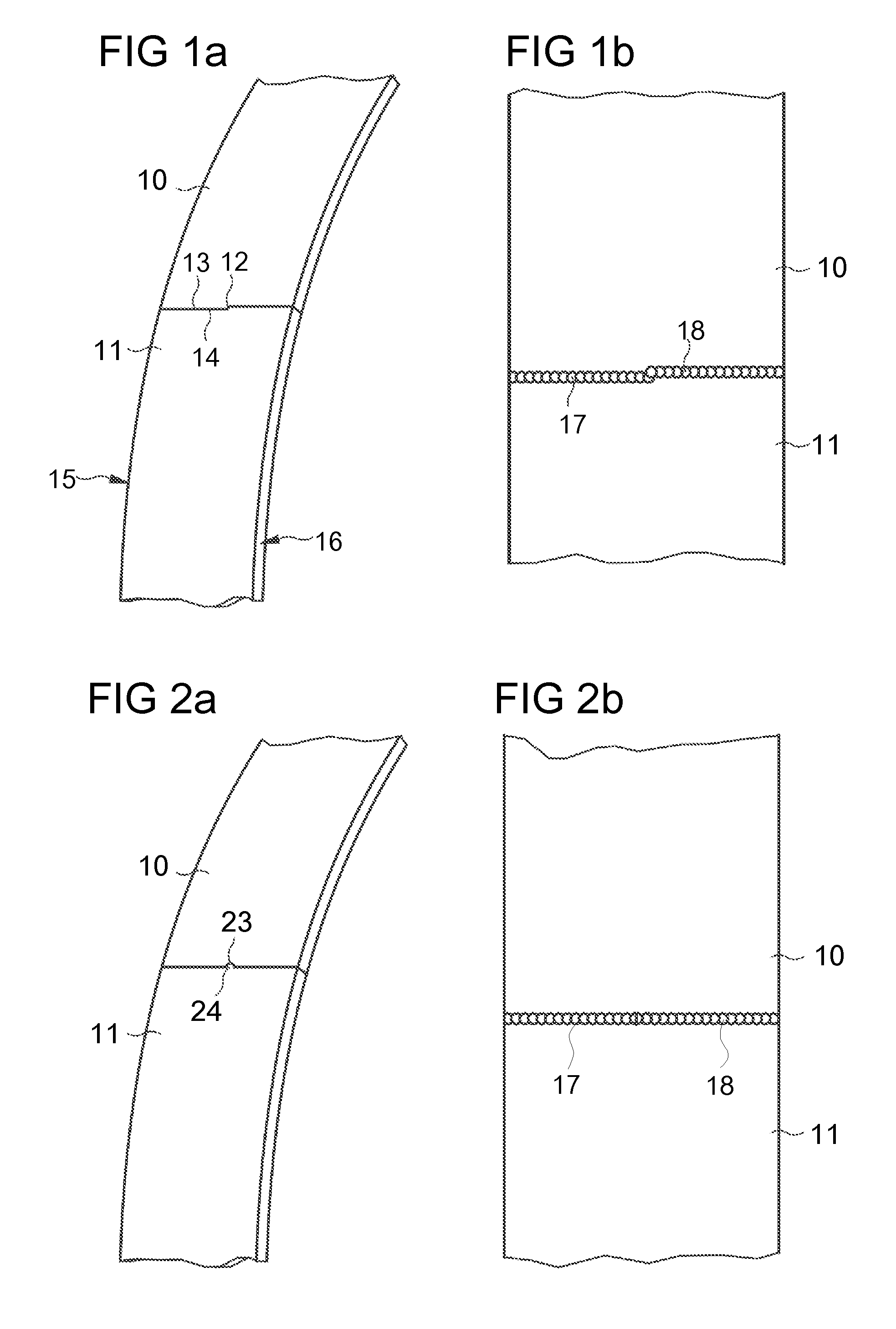
[0005] FIGS. 1a and 1b are perspective representations of a portion of the butt of an annularly bent band before and after welding; and
[0006] FIGS. 2a and 2b are similar representations with an alternative shape of the butt.
DETAILED DESCRIPTION OF EMBODIMENTS
[0007] In FIG. 1a, the butt where both band ends 10, 11 are welded together has an offset in the form of a step 12 lying within the plane of the band, at which a projecting portion 13 of one band end 10 is opposite to a recessing portion 14 at the other band end 11. The step is formed midway between both band edges 15, 16.
[0008] In the welding process, welding is performed from both band edges 15, 16 up to the step 12. Due to the offset, a higher welding quality is achieved in the area of overlap of both weld seams 17, 18 at the respective location. The offset is only so big that a controlled weld connection between both abutting band ends 10, 11 is formed also at this location.
[0009] If there is no interruption (offset) at the overlapping location of the two weld seams 17, 18, a weld puddle is formed twice at the abutting bend ends. This leads to a reduced welding quality in the overlapping region. Due to the offset, the effects of the double weld puddle on the welding quality are less and more consistent.
[0010] The embodiment of FIGS. 2a and 2b differs from that of FIGS. 1a and 1b in that the offset is formed as a recess 23 in one band end 10 that is engaged by a projection 24 at the other band end 11.
[0011] Rings, so-called multi-crimp-rings, are produced in different ways. In one known method, an axially or helically welded tube is divided into rings of desired widths which are subsequently deburred. Disadvantages of this known method are high minimum production volumes required for reasons of cost, correspondingly low flexibility in case of different diameters, and high stock keeping cost for the tube blanks.
[0012] In an alternative production method, sections of a length corresponding to the ring diameter are cut from a deburred band cleaved along straight or inclined lines and their ends are welded together.
[0013] US 2012/006176 A1 discloses a stop collar made of a band the two ends of which are butt welded together.
[0014] When welding the band ends, a weld that is flush with the edge of the ring can be obtained at the start of the welding process. At the weld exit on the other ring edge, however, a geometry results which is not flush with the edge.
[0015] In butt-welding a workpiece exposed to bending, is known from EP 1 752 247 A1 to execute the weld in two partial welds which start at the outer ends and overlap one another in the central region to avoid notches at the outer rim of the workpiece.
* * * * *
D00000
D00001
XML
uspto.report is an independent third-party trademark research tool that is not affiliated, endorsed, or sponsored by the United States Patent and Trademark Office (USPTO) or any other governmental organization. The information provided by uspto.report is based on publicly available data at the time of writing and is intended for informational purposes only.
While we strive to provide accurate and up-to-date information, we do not guarantee the accuracy, completeness, reliability, or suitability of the information displayed on this site. The use of this site is at your own risk. Any reliance you place on such information is therefore strictly at your own risk.
All official trademark data, including owner information, should be verified by visiting the official USPTO website at www.uspto.gov. This site is not intended to replace professional legal advice and should not be used as a substitute for consulting with a legal professional who is knowledgeable about trademark law.