Load Bearing Assistance Apparatus For Lower Extremity Orthotic Or Prosthetic Devices
BILODEAU; Katia ; et al.
U.S. patent application number 16/072871 was filed with the patent office on 2018-12-27 for load bearing assistance apparatus for lower extremity orthotic or prosthetic devices. The applicant listed for this patent is B-TEMIA INC.. Invention is credited to Stephane BEDARD, Katia BILODEAU, Benoit GILBERT.
| Application Number | 20180369056 16/072871 |
| Document ID | / |
| Family ID | 59396816 |
| Filed Date | 2018-12-27 |


| United States Patent Application | 20180369056 |
| Kind Code | A1 |
| BILODEAU; Katia ; et al. | December 27, 2018 |
LOAD BEARING ASSISTANCE APPARATUS FOR LOWER EXTREMITY ORTHOTIC OR PROSTHETIC DEVICES
Abstract
A load bearing assistance apparatus for transferring load from a lower extremity orthotic or prosthetic device to the ground. The load bearing assistance apparatus includes a lateral and a medial spring-loaded members and a linking mechanism for connecting the load bearing assistance apparatus to the lower extremity orthotic or prosthetic device. The linking mechanism also connects the lateral and medial spring-loaded members in a spaced apart configuration so as to position them adjacent the lateral and medial portions, respectively, of the foot of the user of the lower extremity orthotic or prosthetic device and such that a portion of the lateral and medial spring-loaded members enters in contact with the ground during locomotion.
| Inventors: | BILODEAU; Katia; (Quebec, CA) ; GILBERT; Benoit; (Lac Beauport, CA) ; BEDARD; Stephane; (Levis, CA) | ||||||||||
| Applicant: |
|
||||||||||
|---|---|---|---|---|---|---|---|---|---|---|---|
| Family ID: | 59396816 | ||||||||||
| Appl. No.: | 16/072871 | ||||||||||
| Filed: | January 25, 2017 | ||||||||||
| PCT Filed: | January 25, 2017 | ||||||||||
| PCT NO: | PCT/CA2017/000017 | ||||||||||
| 371 Date: | July 25, 2018 |
Related U.S. Patent Documents
| Application Number | Filing Date | Patent Number | ||
|---|---|---|---|---|
| 62286903 | Jan 25, 2016 | |||
| Current U.S. Class: | 1/1 |
| Current CPC Class: | A61F 2/66 20130101; A61F 5/0127 20130101; A61F 2002/6685 20130101; A61H 2201/164 20130101; A61H 2201/165 20130101; A61F 2005/0179 20130101; A61H 2201/0192 20130101; A61H 3/00 20130101; A61F 5/0111 20130101; A61F 2002/6671 20130101; A61F 2002/6664 20130101 |
| International Class: | A61H 3/00 20060101 A61H003/00; A61F 5/01 20060101 A61F005/01 |
Claims
1. A load bearing assistance apparatus for transferring load from a lower extremity orthotic or prosthetic device to the ground, comprising: a lateral and a medial spring-loaded members; and a linking mechanism for connecting the load bearing assistance apparatus to the lower extremity orthotic or prosthetic device and connecting the lateral and medial spring-loaded members in a spaced apart configuration so as to position the lateral and medial spring-loaded members adjacent a lateral and a medial portions, respectively, of a foot of a user of the lower extremity orthotic or prosthetic device and such as a portion of the lateral and medial spring-loaded members enters in contact with the ground during locomotion; wherein in use the lateral and medial spring-loaded members transfer the load from the lower extremity orthotic or prosthetic device to the ground.
2. The load bearing assistance apparatus of claim 1, wherein each of the lateral and medial spring-loaded members is composed of a first and second convex elements connected at respective ends.
3. The load bearing assistance apparatus of claim 1, wherein each of the lateral and medial spring-loaded members is composed of a side-wise C-like and a slightly downwardly curved longitudinal elements connected along respective portions located between corresponding ends and point of maximum curvature.
4. The load bearing assistance apparatus of claim 1, wherein each of the lateral and medial spring-loaded members is composed of two opposed side-wise C-like elements connected so as to form a S-like shape.
5. The load bearing assistance apparatus of claim 1, further comprising a spring-loaded members tension adjustment mechanism.
6. The load bearing assistance apparatus of claim 5, wherein the tension adjustment mechanism is a spring-loaded members height adjustment mechanism.
Description
CROSS-REFERENCE TO RELATED APPLICATIONS
[0001] This application claims the benefits of U.S. provisional patent application No. 62/286,903 filed on Jan. 25, 2016, which is herein incorporated by reference.
TECHNICAL FIELD
[0002] The present disclosure relates to a load bearing assistance apparatus for lower extremity orthotic or prosthetic devices. More specifically, the present disclosure relates to a load bearing assistance apparatus for transferring load from a lower extremity orthotic or prosthetic device to the ground.
BACKGROUND
[0003] Soldiers and other users of lower extremity orthotic devices must support the weight of their gear as well as the weight of the devices.
[0004] A common solution is to provide lower extremity orthotic devices with a ground contact portion positioned underneath the foot of the wearer, for example by a metal sole placed under the foot. However, such solution has for effect to completely separate the wearer from his environment and thus reduces the stability and agility of the wearer.
[0005] Accordingly, there is a need for a load bearing assistance apparatus for lower extremity orthotic or prosthetic devices that does not completely separates the wearer from his environment.
SUMMARY
[0006] The present disclosure provides a load bearing assistance apparatus for transferring load from a lower extremity orthotic or prosthetic device to the ground, comprising: [0007] a lateral and a medial spring-loaded members; and [0008] a linking mechanism for connecting the load bearing assistance apparatus to the lower extremity orthotic or prosthetic device and connecting the lateral and medial spring-loaded members in a spaced apart configuration so as to position the lateral and medial spring-loaded members adjacent a lateral and a medial portions, respectively, of a foot of a user of the lower extremity orthotic or prosthetic device and such as a portion of the lateral and medial spring-loaded members enters in contact with the ground during locomotion; [0009] wherein in use the lateral and medial spring-loaded members transfer the load from the lower extremity orthotic or prosthetic device to the ground.
[0010] The present disclosure also provides a load bearing assistance apparatus as disclosed above, wherein each of the lateral and medial spring-loaded members is composed of a first and second convex elements connected at respective ends, a side-wise C-like and a slightly downwardly curved longitudinal elements or two opposed side-wise C-like elements connected so as to form a S-like shape.
[0011] The present disclosure further provides a load bearing assistance apparatus as disclosed above, further comprising a spring-loaded members tension adjustment mechanism, for example a spring-loaded members height adjustment mechanism.
BRIEF DESCRIPTION OF THE FIGURES
[0012] Embodiments of the disclosure will be described by way of examples only with reference to the accompanying drawings, in which:
[0013] FIG. 1 is a front elevation perspective view of a user wearing lower extremity orthotic devices provided with load bearing assistance apparatuses in accordance with an illustrative embodiment of the present disclosure;
[0014] FIG. 2 is a front elevation perspective view of the load bearing assistance apparatuses of FIG. 1;
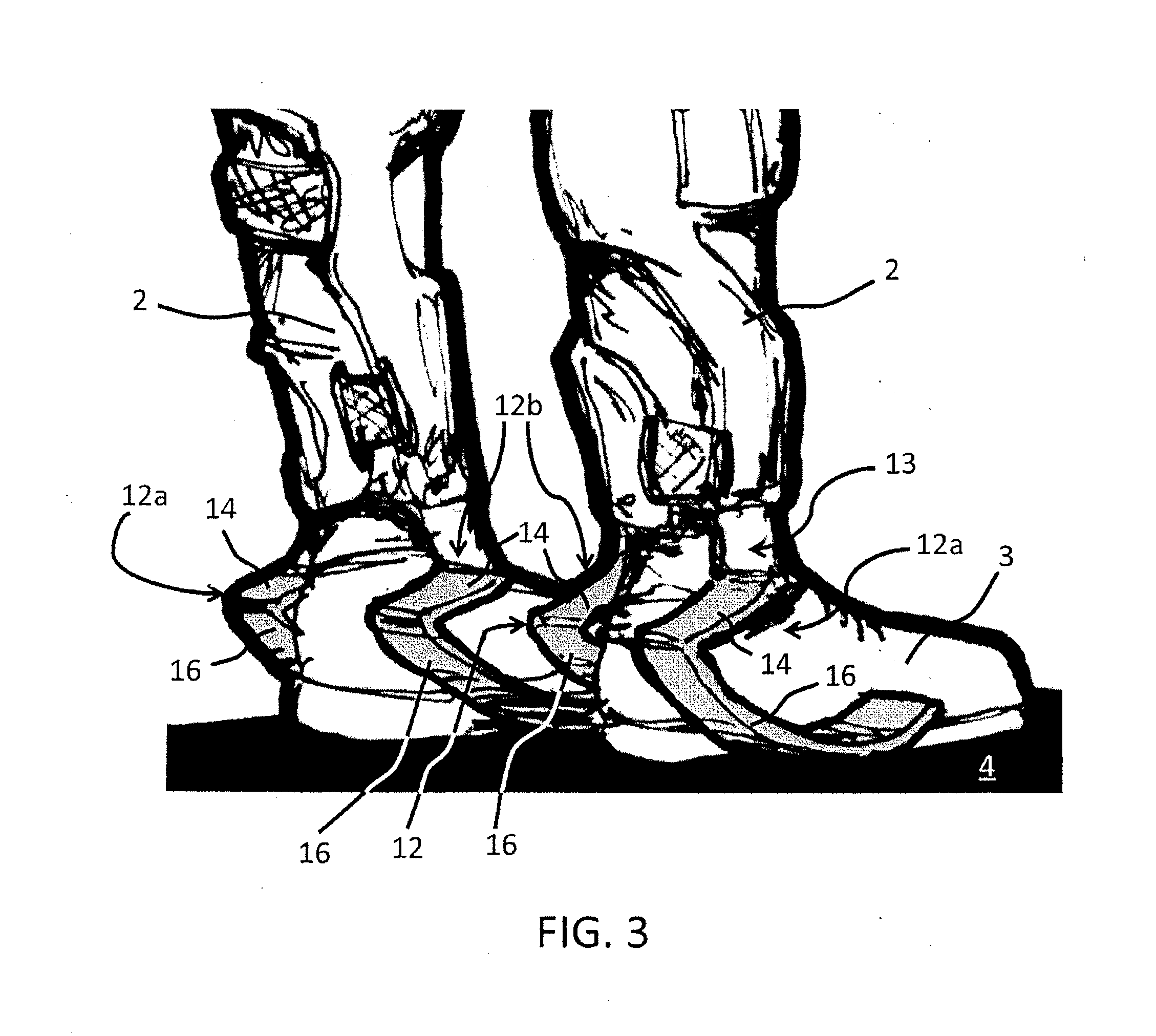
[0015] FIG. 3 is a back elevation perspective view of the load bearing assistance apparatuses of FIG. 1.
[0016] FIG. 4 is a front elevation perspective view of spring-loaded members in accordance with a first alternative embodiment of the present disclosure;
[0017] FIGS. 5A, 5B and 5C are schematic side views of the spring-loaded members of FIG. 4 showing ground contact during walking;
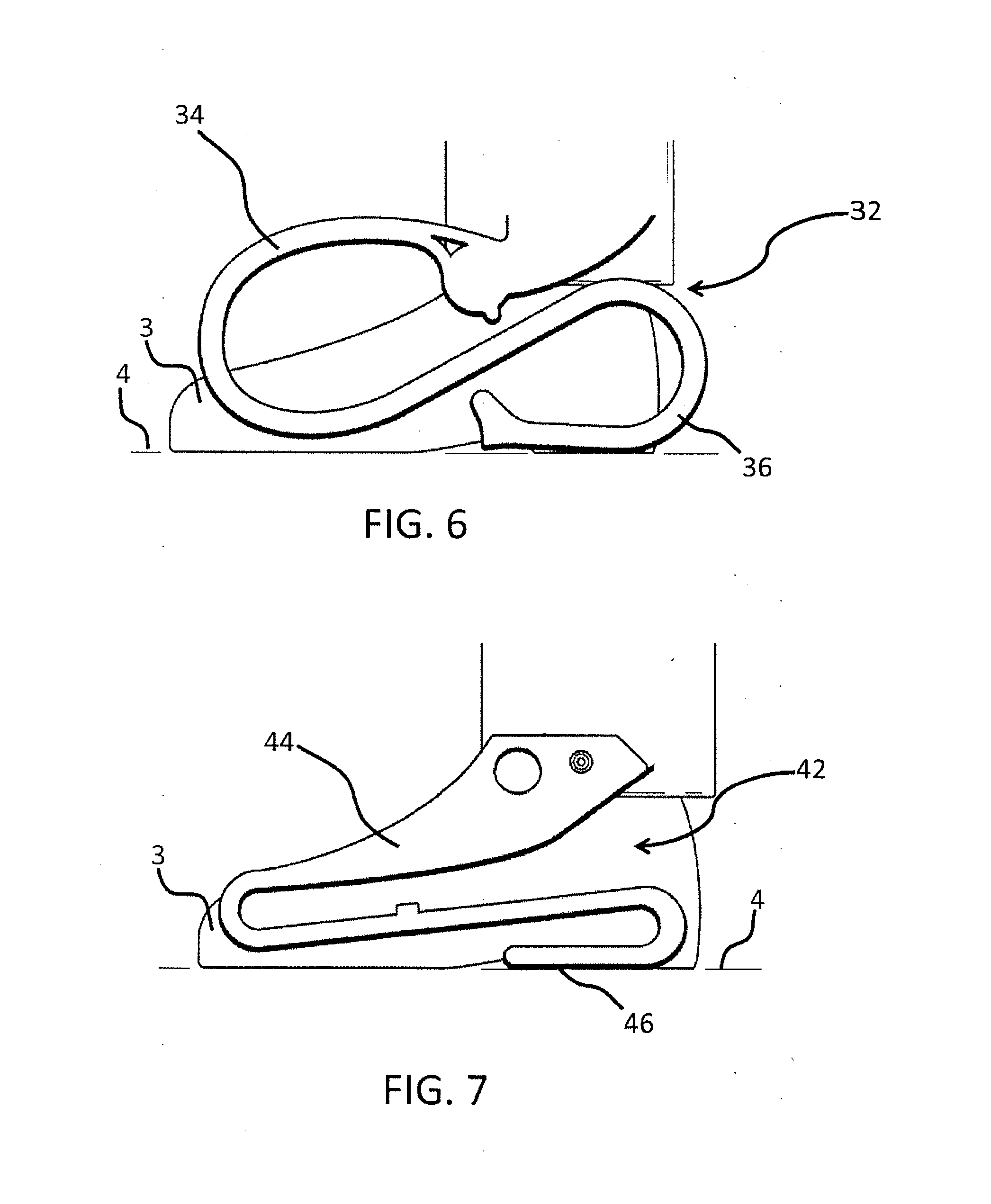
[0018] FIG. 6 is a schematic side view of a spring-loaded member in accordance with a second alternative embodiment of the present disclosure; and
[0019] FIG. 7 is a schematic side view of a spring-loaded member in accordance with a third alternative embodiment of the present disclosure.
[0020] Similar references used in different Figures denote similar components.
DETAILED DESCRIPTION
[0021] Generally stated, the non-limitative illustrative embodiments of the present disclosure provide a load bearing assistance apparatus for lower extremity orthotic or prosthetic devices that transfers all or part of the load from a lower extremity orthotic or prosthetic device to the ground while allowing the user to maintain contact with his environment.
[0022] Referring to FIG. 1, there is shown a user 1 wearing lower extremity orthotic devices 2 provided with load bearing assistance apparatuses 10 in accordance with an illustrative embodiment of the present disclosure.
[0023] With further reference to FIGS. 2 and 3, the load bearing assistance apparatus 10 consist in a lateral 12a and a medial 12b spring-loaded members, each composed of a first 14 and second 16 convex elements connected at respective ends and a linking mechanism 13 for connecting the load bearing assistance apparatus 10 to a corresponding lower extremity orthotic device 2 and connecting the lateral 12a and medial 12b spring-loaded members in a spaced apart configuration so as to be positioned adjacent the lateral and medial portions, respectively, of the foot 3 of the user 1 of the lower extremity orthotic device 2 and such that the second 16 convex elements of the lateral 12a and medial 12b spring-loaded members are in contact with the ground 4.
[0024] The lateral 12a and medial 12b spring-loaded members provide, respectively, lateral and medial load transfer mechanical chains, which each partly absorb the weight of the associated orthotic device 2 and in some embodiments take over some of the dorsal load of the user as well. It is thus these four mechanical chains (one lateral and one medial mechanical chain for each of the left and right foot) that provide the load transfer capability from the lower extremity orthotic (or prosthetic) devices 2 to the ground 4.
[0025] Because of their positioning, the lateral 12a and medial 12b spring-loaded members transfer the load of the orthotic device 2 to the ground 4 regardless of the nature of the ground 4 (i.e. horizontal, stairs, uphill, downhill, etc.), while maintaining mobility (i.e. flexion/extension, inversion/eversion) of the foot 3, thus improving the user's 1 stability.
[0026] The shape of the second convex element 16 is optimized so as to be in contact with the ground 4 during all phases of locomotion (i.e. walking, running, etc.). Each spring-loaded member 12a, 12b is sufficiently robust so as to completely support the load of its associated orthotic device 2, for example when the user 1 is traveling over uneven terrain. In an alternative embodiment, the spring-loaded members 12a, 12b may be provided with a tension adjustment mechanism, for example a height adjustment mechanism, in order to adjust their load bearing capacity to suit various loads.
[0027] Referring now to FIG. 4, there is shown a lateral 22a and a medial 22b spring-loaded members in accordance with a first alternative embodiment. Each spring-loaded member 22a, 22b is composed of a side-wise C-like (U-like, cup-like, etc.) element 24 and a slightly downwardly curved longitudinal element 26.
[0028] Referring to FIGS. 5A, 5B and 5C, there is shown contact of each of the spring-loaded members 22 with the ground 4 during locomotion. During heel strike a portion of the curved longitudinal element 26 is in contact with the ground 4, then during forefoot contact portions of both the C-like 24 and curved longitudinal 26 elements are in contact with the ground 4 and finally, during heel lift/forefoot loading a portion of the C-like 24 element is in contact with the ground 4.
[0029] Referring to FIG. 6, there is shown a spring-loaded member 32 in accordance with a second alternative embodiment of the present disclosure. The spring-loaded member 32 is composed of two opposed side-wise C-like (U-like, cup-like, etc.) elements 34, 36 connected so as to form a generally S-like (serpentine-like, etc.) shape such that portions of either or both of the C-like elements 34, 36 are in contact with the ground 4 during locomotion.
[0030] It is to be understood that the shape (i.e. curvature, deformation, etc.) of the opposed side-wise C-like elements 34 and/or 36 may vary. For example, referring to FIG. 7, there is shown a spring-loaded member 42 in accordance with a third alternative embodiment of the present disclosure, composed of two the opposed side-wise C-like (U-like, cup-like, etc.) elements 44, 46 connected so as to form a generally compressed S-like (serpentine-like, etc.).
[0031] It is to be understood that in FIGS. 6 and 7 only one of the two spring-loaded members 32, 42 is shown as the lateral and medial spring-loaded members are similar in configuration.
[0032] It is further to be understood that depending on the exact configuration of the spring-loaded member 12, 22, 32, 42, one or more portions of either or both of the elements (14, 16), (24, 26), (34, 36), (44, 46) may be in contact with the ground 4 during locomotion.
[0033] Although the present disclosure has been described by way of particular non-limiting illustrative embodiments and examples thereof, it should be noted that it will be apparent to persons skilled in the art that modifications may be applied to the present particular embodiment without departing from the scope of the present disclosure as hereinafter claimed.
* * * * *
D00000
D00001
D00002
D00003
D00004
D00005
D00006
XML
uspto.report is an independent third-party trademark research tool that is not affiliated, endorsed, or sponsored by the United States Patent and Trademark Office (USPTO) or any other governmental organization. The information provided by uspto.report is based on publicly available data at the time of writing and is intended for informational purposes only.
While we strive to provide accurate and up-to-date information, we do not guarantee the accuracy, completeness, reliability, or suitability of the information displayed on this site. The use of this site is at your own risk. Any reliance you place on such information is therefore strictly at your own risk.
All official trademark data, including owner information, should be verified by visiting the official USPTO website at www.uspto.gov. This site is not intended to replace professional legal advice and should not be used as a substitute for consulting with a legal professional who is knowledgeable about trademark law.