Magnetic Writer Having Convex Trailing Surface Pole And Conformal Write Gap
PAN; Yu ; et al.
U.S. patent application number 15/698958 was filed with the patent office on 2017-12-28 for magnetic writer having convex trailing surface pole and conformal write gap. The applicant listed for this patent is Western Digital (Fremont), LLC. Invention is credited to ZHIGANG BAI, Tao LIN, Yu PAN, Yugang WANG, Peng Zhao.
| Application Number | 20170372728 15/698958 |
| Document ID | / |
| Family ID | 59828532 |
| Filed Date | 2017-12-28 |


| United States Patent Application | 20170372728 |
| Kind Code | A1 |
| PAN; Yu ; et al. | December 28, 2017 |
MAGNETIC WRITER HAVING CONVEX TRAILING SURFACE POLE AND CONFORMAL WRITE GAP
Abstract
A magnetic write apparatus has a media-facing surface (MFS), a pole, a write gap, a top shield and coil(s). The pole includes a yoke and a pole tip. The pole tip includes a bottom, a top wider than the bottom and first and second sides. The pole tip has a height between the top and the bottom. At least part of the top of the pole tip is convex in a cross-track direction between the first and second sides such that the height at the MFS is larger between the first and second sides than at the first and second sides. The height increases in a yoke direction perpendicular to the MFS. The write gap is adjacent to and conformal with the top of the pole at the MFS and is between part of the top shield and the pole. The top shield is concave at the MFS.
| Inventors: | PAN; Yu; (Fremont, CA) ; WANG; Yugang; (Milpitas, CA) ; BAI; ZHIGANG; (Fremont, CA) ; LIN; Tao; (San Jose, CA) ; Zhao; Peng; (San Ramon, CA) | ||||||||||
| Applicant: |
|
||||||||||
|---|---|---|---|---|---|---|---|---|---|---|---|
| Family ID: | 59828532 | ||||||||||
| Appl. No.: | 15/698958 | ||||||||||
| Filed: | September 8, 2017 |
Related U.S. Patent Documents
| Application Number | Filing Date | Patent Number | ||
|---|---|---|---|---|
| 14956168 | Dec 1, 2015 | 9767831 | ||
| 15698958 | ||||
| Current U.S. Class: | 1/1 |
| Current CPC Class: | G11B 5/1871 20130101; G11B 5/23 20130101; G11B 5/3116 20130101; G11B 5/232 20130101; G11B 5/112 20130101; G11B 5/315 20130101; G11B 5/1278 20130101 |
| International Class: | G11B 5/31 20060101 G11B005/31; G11B 5/127 20060101 G11B005/127; G11B 5/187 20060101 G11B005/187; G11B 5/23 20060101 G11B005/23; G11B 5/11 20060101 G11B005/11 |
Claims
1. A magnetic write apparatus comprising: a pole comprising a pole tip, the pole tip comprising: a bottom extending parallel to a cross track direction that is perpendicular to a media facing surface; a top extending in the cross track direction and wider than the bottom; a first side extending between the top and the bottom in a down track direction that is parallel to the media facing surface; and a second side extending in the down track direction between the top and the bottom, wherein the pole tip has a height between the top and the bottom, and the height increases from the media facing surface in a yoke direction that is perpendicular to the media facing surface; wherein at the media facing surface the pole tip forms a first angle at the first side between the top and a plane that extends parallel to the cross track direction; and wherein at a position recessed from the media facing surface, the first angle decreases to a second angle at the first side between the top and the plane.
2. The magnetic write apparatus of claim 1, wherein the pole has a width between the first side and the second side in the cross track direction, and wherein the width increases from the media facing surface in the yoke direction.
3. The magnetic write apparatus of claim 1, wherein the top has a convex surface.
4. The magnetic write apparatus of claim 1, wherein the second angle changes continuously with distance in the yoke direction.
5. The magnetic write apparatus of claim 1, wherein the pole tip forms a third angle at the second side between the top and the plane at the media facing surface, and wherein the third angle is equal to the first angle.
6. The magnetic write apparatus of claim 1, wherein the pole tip forms a fourth angle at the second side between the top and the plane at the position recessed from the media facing surface, and wherein the fourth angle is equal to the second angle.
7. The magnetic write apparatus of claim 1, wherein the first angle is greater than zero degrees and not more than twenty degrees.
8. The magnetic write apparatus of claim 1, further comprising a write gap that is conformal with a shape of the top in the cross track direction.
9. The magnetic write apparatus of claim 8, wherein the write gap comprises overhangs that extend past the first side and second side of the pole tip.
10. The magnetic write apparatus of claim 1, wherein the height is not more than one hundred nanometers.
11. A magnetic write apparatus comprising: a pole comprising a pole tip and a yoke, the pole tip comprising: a bottom extending parallel to a cross track direction that is perpendicular to a media facing surface; a top extending in the cross track direction and wider than the bottom; a first side extending between the top and the bottom in a down track direction that is parallel to the media facing surface; and a second side extending in the down track direction between the top and the bottom, wherein at the media facing surface, the pole tip forms a first angle at the first side between the top and a plane that extends along the cross track direction and a second angle at the second side between the top and the plane; wherein a value of the first angle is different from a value of the second angle; and wherein the value of the first angle and the value of the second angle is greater than zero degrees and not more than twenty degrees.
12. The magnetic write apparatus of claim 11, wherein the top has a convex curved surface.
13. The magnetic write apparatus of claim 11, wherein the top has a convex peaked surface.
14. The magnetic write apparatus of claim 11, wherein the pole tip has a height between the top and the bottom, and wherein the height increases from the media facing surface in a yoke direction that is perpendicular to the media facing surface.
15. The magnetic write apparatus of claim 11, wherein the pole tip has a width between the first side and the second side, and wherein the width increases from the media facing surface in a yoke direction that is perpendicular to the media facing surface.
16. A magnetic write apparatus comprising: a pole comprising a pole tip, the pole tip comprising: a bottom extending parallel to a cross track direction that is perpendicular to a media facing surface; a top extending in the cross track direction and wider than the bottom; a first side extending between the top and the bottom in a down track direction that is parallel to the media facing surface; and a second side extending in the down track direction between the top and the bottom, wherein the pole tip has a height between the top and the bottom that increases from the media facing surface in a yoke direction that is perpendicular to the media facing surface; and wherein the pole tip has a width between the first side and the second side that increases from the media facing surface in the yoke direction.
17. The magnetic write apparatus of claim 16, wherein the pole tip forms a first angle at the first side between the top and a plane that extends along the cross track direction, and a second angle at the second side between the top and the plane, wherein the first angle and the second angle are formed at the media facing surface and are equal in value.
18. The magnetic write apparatus of claim 17, wherein the pole tip forms a third angle at the first side between the top and the plane, and a fourth angle at the second side between the top and the plane, wherein the third angle and the fourth angle are formed at a position recessed from the media facing surface, and wherein the third angle is equal to the first angle and the fourth angle is equal to the second angle.
19. The magnetic write apparatus of claim 17, wherein the pole tip forms a third angle at the first side between the top and the plane, and a fourth angle at the second side between the top and the plane, wherein the third angle and the fourth angle are formed at a position recessed from the media facing surface, and wherein the third angle is less the first angle and the fourth angle is less than the second angle.
20. The magnetic write apparatus of claim 16, wherein the pole tip forms a first angle at the first side between the top and a plane that extends along the cross track direction, and a second angle at the second side between the top and the plane, wherein the first angle and the second angle are formed at the media facing surface and are different in value.
Description
CROSS-REFERENCE TO RELATED APPLICATION
[0001] This application is a divisional of U.S. application Ser. No. 14/956,168, filed on Dec. 1, 2015, the entirety of which is incorporated by reference herein.
BACKGROUND
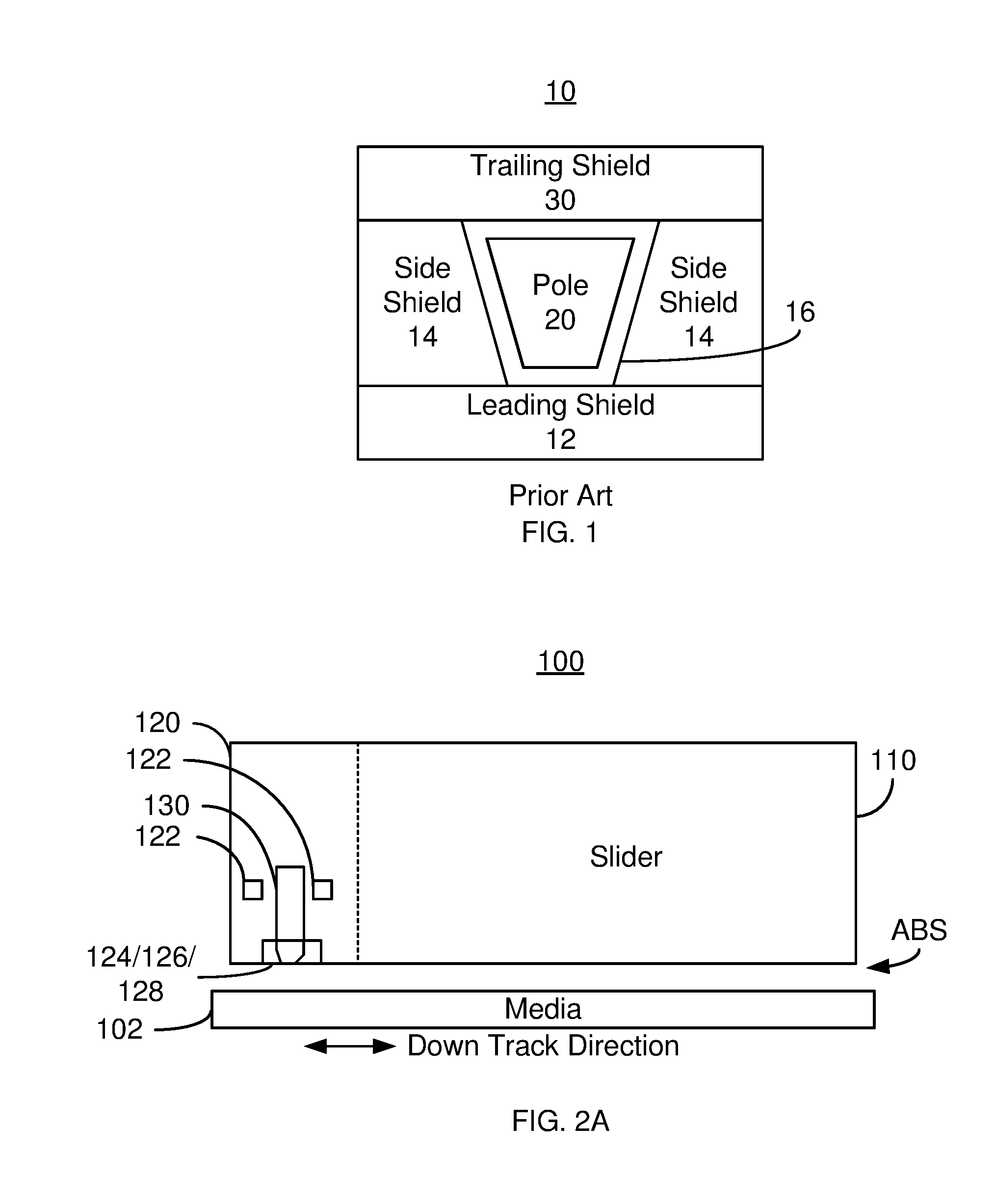
[0002] FIG. 1 depicts an air-bearing surface (ABS) view of a conventional magnetic recording apparatus 10. The magnetic recording apparatus 10 may be a perpendicular magnetic recording (PMR) apparatus or other magnetic write apparatus. The conventional magnetic recording apparatus 10 may be a part of a merged head including the write apparatus 10 and a read apparatus (not shown). Alternatively, the magnetic recording head may only include the write apparatus 10.
[0003] The write apparatus 10 includes a leading shield 12, side shield(s) 14, gap 16, a pole 20 and a trailing shield 30. The apparatus 10 may also include other components including but not limited to coils for energizing the pole 20. The top (trailing surface) of the pole 20 is wider than the bottom (leading surface) of the pole 20.
[0004] Although the conventional magnetic recording apparatus 10 functions, there are drawbacks. In particular, the conventional magnetic write apparatus 10 may not perform sufficiently at higher recording densities. For example, at higher recording densities, the pole 20 is desired to be smaller, at least at the ABS. The conventional write apparatus 10 may be not provide a sufficiently high field or the desired field gradient for writing to a media (not shown). Stated differently, the writeability of the conventional pole 20 may suffer. Accordingly, what is needed is a system and method for improving the performance of a magnetic recording head, particularly at higher areal densities.
BRIEF DESCRIPTION OF THE DRAWINGS
[0005] FIG. 1 depicts an ABS view of a conventional magnetic recording apparatus.
[0006] FIGS. 2A, 2B, 2C and 2D depict side, MFS, recessed and apex views of an exemplary embodiment of a magnetic write apparatus usable in a magnetic recording disk drive.
[0007] FIG. 3 depicts a view of the field profile at the media.
[0008] FIGS. 4A and 4B depict ABS and recessed views of another exemplary embodiment of a magnetic write apparatus usable in a magnetic recording disk drive.
[0009] FIGS. 5A, 5B and 5C depict MFS, recessed and apex views of another exemplary embodiment of a magnetic write apparatus usable in a magnetic recording disk drive.
[0010] FIG. 6 depicts an ABS view of another exemplary embodiment of a magnetic write apparatus usable in a disk drive.
[0011] FIG. 7 depicts an ABS view of another exemplary embodiment of a magnetic write apparatus usable in a disk drive.
[0012] FIG. 8 depicts an ABS view of another exemplary embodiment of a magnetic write apparatus usable in a disk drive.
[0013] FIG. 9 depicts an ABS view of another exemplary embodiment of a magnetic write apparatus usable in a disk drive.
[0014] FIG. 10 is a flow chart depicting an exemplary embodiment of a method for fabricating a magnetic write apparatus drive usable in a disk drive.
DETAILED DESCRIPTION
[0015] While the various embodiments disclosed are applicable to a variety of data storage devices such as magnetic recording disk drives, solid-state hybrid disk drives, networked storage systems, for the purposes of illustration the description below uses disk drives as examples.
[0016] FIGS. 2A, 2B, 2C and 2D depict side, media-facing surface (MFS), yoke and apex views of an exemplary embodiment of a magnetic write apparatus 120 usable in a magnetic recording disk drive 100. FIG. 2A depicts a side view of the disk drive 100. FIG. 2B depicts an MFS view of the write apparatus 120. FIG. 2C depicts a recessed view of the write apparatus 120. Thus, the view taken in FIG. 2C at a distance from the ABS in the yoke direction perpendicular to the ABS. FIG. 2D is an apex view of the write apparatus. For clarity, FIGS. 2A-2D are not to scale. For simplicity not all portions of the disk drive 100 and write apparatus 120 are shown. In addition, although the disk drive 100 and write apparatus 120 are depicted in the context of particular components other and/or different components may be used. For example, circuitry used to drive and control various portions of the disk drive is not shown. Only single components are shown. However, multiples of each components and/or their sub-components, might be used. The write apparatus 120 may be a perpendicular magnetic recording (PMR) writer. However, in other embodiments, the write apparatus 120 may be configured for other types of magnetic recording. The disk drive 100 typically includes the write apparatus 120 and a read apparatus. However, only the write apparatus 120 is depicted.
[0017] The disk drive 100 includes a media 102, and a slider 110 on which the write apparatus 120 has been fabricated. Although not shown, the slider 110 and thus the write apparatus 120 are generally attached to a suspension. The write apparatus 120 includes a media-facing surface (MFS). Because the write apparatus 120 is used in a disk drive, the MFS is an air-bearing surface (ABS).
[0018] The write apparatus 120 includes coil(s) 122, side gap 121, optional leading (bottom) shield 124, optional side shields 126, a pole 130, write gap 125 and trailing (top) shield 128. The trailing shield 128 is separated from the pole 130 by the write gap 124. Similarly, the side shields 126 and bottom shield 124 are separated from the sidewalls of the pole 130 by gap 121. Although shown as a single gap 121, the side gap and bottom gap may be fabricated separately. The gap 121 and write gap 125 are nonmagnetic. The side shields 124 may be magnetically connected with the trailing shield 128 and/or the leading shield 124. The coils 122 are used to energize the pole 130. Although one turn is shown in FIG. 2A, another number may be used. For example, in some embodiments, additional turns (not shown in FIG. 2A) may be used. The coil(s) 122 may be helical or spiral coils.
[0019] The pole 130 includes a pole tip 131 closer to the ABS and a yoke 133 further from the ABS. In the embodiment shown, a portion of the pole tip 131 occupies the ABS. The pole tip 131 has sidewalls 134 and 136, bottom (leading surface) 132 and top (trailing surface) 138. In the embodiment shown, the top 138 of the pole tip is wider than the bottom 132 in the cross track direction. In some embodiments, the track width of the pole 130 in the cross-track direction is on the order of at least forty and not more than sixty nanometers. However, other track widths, including smaller track widths, are possible.
[0020] The top 138 of the pole tip 131 is convex. More specifically, the top 138 of the pole tip 131 is a convex curved surface. The pole tip 131 thus has a height between the top 138 and the bottom 132 that varies across the ABS. The height at the center, hm1, is larger than the height at the edges, hs1, of the pole tip 131. The top 138 of the pole tip 131 forms angle .alpha. with the cross-track direction at the edges 134 and 136. This angle is greater than zero degrees and not more than twenty degrees. The angle may also not exceed fifteen degrees in some cases. In some embodiments, this angle is at least five degrees and not more than ten degrees. In the embodiment shown, the angles the top 138 makes at the sides 134 and 136 are the same. Stated differently, the convex top 138 of the pole tip 131 is symmetric in the cross-track direction. The maximum height is at the center of the pole tip 131. In some embodiments, the maximum height, hm1, at the ABS is not more than one hundred nanometers. In some embodiments the maximum height at the ABS may be at least eighty nanometers. However, other heights are possible. In the embodiment shown, the entire top 138 of the pole tip 131 is convex. In other embodiments, only a portion of the top 138 is convex.
[0021] In addition, as can be seen in FIGS. 2B-2D, the height and width of the pole 130 increase in the yoke direction. The top 138 of the pole tip 131 is beveled such that the height increases in the yoke direction perpendicular to the ABS. In the embodiment shown, the bottom 132 of the pole tip 131 is also beveled. This may be best seen in FIG. 2D. However, in other embodiments the bottom 132 may be flat. For example, at the ABS, the pole tip 131 has maximum height hm1 as shown in FIG. 2B. At some distance from the ABS in the yoke direction, the pole tip 131 has a larger maximum height hm2. Similarly, as can be seen in FIGS. 2B and 2C, the width of the pole tip 131 increases. However, as is indicated in FIGS. 2B and 2C, the angle(s) the top 138 makes with the cross-track direction are substantially constant. Because the angles .alpha. are substantially constant and the pole tip 131 widens, the height of the pole tip 131 naturally increases for the embodiment shown in FIGS. 2A-2D.
[0022] At the ABS, the write gap 125 is conformal with the top 138 of the pole tip 131 in the cross-track direction. Because the write gap 125 is conformal, the portion of the trailing shield 128 opposite to the convex portion of the pole tip top 138 may be concave. In some embodiments, the write gap 125 is thin. For example, the write gap 125 may be less than thirty nanometers. In some embodiments, the write gap 125 may not exceed twenty-five nanometers. However, other thicknesses are possible. In the embodiment shown, the write gap 125 also includes overhangs which extend past the gap 121 and reside over a portion of the side shields 126. Although the write gap 125 is conformal in the cross-track direction, the write gap 125 can, but need not be, conformal with the top 138 of the pole tip 131 in the yoke direction. For example, as can be seen in FIG. 2D, the thickness of the write gap 125 increases slightly in the yoke direction perpendicular to the ABS.
[0023] The disk drive 100 and write apparatus 120 may have improved performance at higher magnetic recording areal densities. The convex top 138 of the pole tip 131 allows the volume of the pole 130 to be increased for a constant track width. Thus, the pole 130 may provide a higher magnetic field and more desirable magnetic field gradient. It was believed that the convex top 138 might adversely affect the shape of the magnetic field provided to the media. However, for the angles, a, in the ranges described above, the change in the magnetic field shape is sufficiently small that an improvement in writeability due to the increased magnetic volume offsets any change in the magnetic field profile. For example, FIG. 3 depicts various magnetic field shapes 111, 127 and 129. Note that the curves 111, 127 and 129 are for explanation only and do not represent specific data from real-world devices. The dashed curve 111 indicates the field shape for a pole having a flat top. The solid curve 127 indicates the magnetic field shape for the pole 130 having an angle .alpha. of approximately five degrees. The dotted curve 129 indicates the magnetic field shape for the pole 130 having an angle .alpha. of approximately fifteen degrees. Thus, although the magnetic field changes, particularly near the top, the change may be sufficiently small that other benefits outweigh the change in the field profile from the angle ranges described above. Thus, field magnitude and gradient may be improved without unduly compromising the field shape. Consequently, the magnetic write apparatus 120 may exhibit improved performance, particularly at higher areal recording densities.
[0024] FIGS. 4A and 4B depict ABS and recessed views of another embodiment of a disk drive 100' and magnetic write apparatus 120'. For clarity, FIGS. 4A and 4B are not to scale. For simplicity not all portions of the disk drive 100'/write apparatus 120' are shown. In addition, although the disk drive 100'/write apparatus 120' is depicted in the context of particular components other and/or different components may be used. For example, circuitry used to drive and control various portions of the disk drive is not shown. For simplicity, only single components are shown. However, multiples of each components and/or their sub-components, might be used. Thus, the write apparatus 120' includes a gap 121, an optional leading shield 124, write gap 125', optional side shields 126, optional trailing shield 128' and convex pole 130' having a pole tip, yoke (not explicitly labeled), bottom 132, sides 134 and 136 and top 138' that are analogous to gap 121, optional leading shield 124, write gap 125, optional side shields 126, optional trailing shield 128 and convex pole 130 having pole tip 131, yoke 133, bottom 132, sides 134 and 136 and top 138, respectively.
[0025] The pole tip for pole 130' may have a width in the cross-track direction and height in the down track direction analogous to that described above for the pole tip 131. The top 138' of the pole tip is convex. More specifically, the top 138' of the pole tip is a convex peaked surface. The pole tip 131 thus has a height between the top 138 and the bottom 132 that varies across the ABS. The height at the center, hm1', is larger than the height at the edges, hs1', of the pole tip. The top 138' of the pole tip forms angle .alpha. with the cross-track direction at the edges 134 and 136. This angle for the pole tip of the pole 130' is in the same range as that for the pole tip 131 of the pole 130. In the embodiment shown, the angles the top 138' makes at the sides 134 and 136 are the same. Stated differently, the convex top 138' of the pole tip 131 is symmetric in the cross-track direction. The maximum height is at the center of the pole tip. In the embodiment shown, the entire top 138' of the pole tip is convex. In other embodiments, only a portion of the top 138' is convex.
[0026] In addition, the height and width of the pole tip for pole 130 increase in the yoke direction. For example, at the ABS, the pole tip has maximum height hm1' as shown in FIG. 4A. At some distance from the ABS in the yoke direction, the pole tip has a larger maximum height hm2' as shown in FIG. 4B. Similarly, as can be seen in FIGS. 4A and 4B, the width of the pole tip increases. However, as is indicated in FIGS. 4A and 4B, the angle(s) the top 138' makes with the cross-track direction are substantially constant. Because the angles .alpha. are substantially constant and the pole tip widens, the height of the pole tip naturally increases.
[0027] At the ABS, the write gap 125' is conformal with the top 138' of the pole tip in the cross-track direction. Because the write gap 125' is conformal, the portion of the trailing shield 128' opposite to the convex portion of the top 138' may be concave. In the embodiment shown, the write gap 125' also includes overhangs which extend past the gap 121 and reside over a portion of the side shields 126'. The thickness of the write gap 125' may also be in the range described above for the write gap 125. Although the write gap 125' is conformal in the cross-track direction, the write gap 125' can, but need not be, conformal with the top 138' of the pole tip in the yoke direction.
[0028] The disk drive 100' and write apparatus 120' may have improved performance at higher magnetic recording areal densities. The convex top 138' of the pole tip allows the volume of the pole 130' to be increased for a constant track width. Thus, the pole 130' may provide a higher magnetic field and more desirable magnetic field gradient. Thus, field magnitude and gradient may be improved without unduly compromising the field shape. Consequently, the magnetic write apparatus 120' may exhibit improved performance, particularly at higher areal recording densities.
[0029] FIGS. 5A, 5B and 5C depict ABS, recessed and apex views of another embodiment of a magnetic write apparatus 140. For clarity, FIGS. 5A-5C are not to scale. For simplicity not all portions of the write apparatus 140 are shown. In addition, although the write apparatus 140 is depicted in the context of particular components other and/or different components may be used. For example, circuitry used to drive and control various portions of the disk drive is not shown. For simplicity, only single components are shown. However, multiples of each components and/or their sub-components, might be used. Thus, the write apparatus 140 includes a gap 141, an optional leading shield 144, write gap 145, optional side shields 146, optional trailing shield 148 and convex pole 150 having a pole tip, yoke (not explicitly labeled), bottom 152, sides 154 and 156 and top 158 that are analogous to the gap, optional leading shield, write gap, optional side shields, optional trailing shield and convex pole having pole tip, yoke, bottom, sides and top, respectively, described above.
[0030] The pole tip for pole 150 may have a width in the cross-track direction and height in the down track direction analogous to that described above for the pole tip 131 of the pole 130/130'. The top 158 of the pole tip is a convex curved surface analogous to the surface 138. However, as can be seen in FIGS. 5A-5C, the angle the top 158 of the pole tip makes at the sides 154 and 156 changes with distance from the ABS in the yoke direction. At the ABS, the top 158 of the pole tip forms angle .alpha.1 with the cross-track direction at the edges 154 and 156. This angle for the pole tip of the pole 150 is in the same range as that for the pole tip 131 of the poles 130 and 130'. Recessed from the ABS, the top 158 of the pole tip forms angle .alpha.2 with the cross-track direction at the edges 154 and 156. Further .alpha.2<.alpha.1. The angle the top 158 of the pole tip forms with the cross-track direction may change continuously with distance from the ABS. As can be seen in FIG. 5C, the height of the pole 150 in the down track direction still increases with increasing distance from the ABS. However, because the angle that the top 158 makes with the cross-track track direction decreases with distance from the ABS, the height of the pole 150 does not increase as rapidly as the height of the pole 130 does. This can be seen in FIG. 5C, in which the height of the pole 130 in the yoke direction is shown by a dotted line. In the embodiment shown, the angles the top 158 makes at the sides 154 and 156 are the same at a given distance from the ABS. Stated differently, the convex top 158 of the pole tip is symmetric in the cross-track direction.
[0031] At the ABS, the write gap 145 is conformal with the top 158 of the pole tip in the cross-track direction. Because the write gap 145 is conformal, the portion of the trailing shield 158 opposite to the convex portion of the top 158 may be concave. In the embodiment shown, the write gap 145 also includes overhangs which extend past the gap 141 and reside over a portion of the side shields 146. The thickness of the write gap 145 may also be in the range described above for the write gaps 125 and 125'. Although the write gap 145 is conformal in the cross-track direction, the write gap 145 can, but need not be, conformal with the top 158 of the pole tip in the yoke direction.
[0032] The write apparatus 140 may have improved performance at higher magnetic recording areal densities. The convex top 158 of the pole tip allows the volume of the pole 150 to be increased for a constant track width. Thus, the pole 150 may provide a higher magnetic field and more desirable magnetic field gradient. Thus, field magnitude and gradient may be improved without unduly compromising the field shape. Consequently, the magnetic write apparatus 140 may exhibit improved performance, particularly at higher areal recording densities.
[0033] FIG. 6 depicts an ABS view of another embodiment of a magnetic write apparatus 160. For clarity, FIG. 6 is not to scale. For simplicity not all portions of the write apparatus 160 are shown. In addition, although the write apparatus 160 is depicted in the context of particular components other and/or different components may be used. For example, circuitry used to drive and control various portions of the disk drive is not shown. For simplicity, only single components are shown. However, multiples of each components and/or their sub-components, might be used. Thus, the write apparatus 160 includes a gap 161, an optional leading shield 164, write gap 165, optional side shields 166, optional trailing shield 168 and convex pole 170 having a pole tip, yoke (not explicitly labeled), bottom 172, sides 174 and 176 and top 178 that are analogous to the gap, optional leading shield, write gap, optional side shields, optional trailing shield and convex pole having pole tip, yoke, bottom, sides and top, respectively, described above. Although only an ABS view is shown, the pole 170 including top surface 178, trailing shield 168 and write gap 165 may vary in the yoke direction in a manner analogous to the pole, pole tip top surface, trailing shield and write gap described above.
[0034] The pole tip for pole 170 may have a width in the cross-track direction and height in the down track direction analogous to that described above for the pole tip of the pole 130, 130' and/or 150. The top 178 of the pole tip is a convex curved surface analogous to the surface 138 and 158. At the ABS, the top 178 of the pole tip forms angle .alpha. with the cross-track direction at the sides 174 and 176. This angle for the pole tip of the pole 170 is in the same range as that for the pole tip 131 of the poles 130 and 130'.
[0035] At the ABS, the write gap 165 is conformal with the top 178 of the pole tip in the cross-track direction. Because the write gap 155 is conformal, the portion of the trailing shield 168 opposite to the convex portion of the top 178 may be concave. In the embodiment shown, the write gap 165 does not include overhangs which extend past the gap 161. The thickness of the write gap 165 may also be in the range described above for the write gaps 125 and 125'. Although the write gap 165 is conformal in the cross-track direction, the write gap 165 can, but need not be, conformal with the top 178 of the pole tip in the yoke direction.
[0036] The write apparatus 160 may share the benefits of the write apparatuses 120, 120' and/or 140. The pole 170 may provide a higher magnetic field and more desirable magnetic field gradient without unduly compromising the field shape. Consequently, the magnetic write apparatus 160 may exhibit improved performance, particularly at higher areal recording densities.
[0037] FIG. 7 depicts an ABS view of another embodiment of a magnetic write apparatus 160'. For clarity, FIG. 7 is not to scale. For simplicity not all portions of the write apparatus 160' are shown. In addition, although the write apparatus 160' is depicted in the context of particular components other and/or different components may be used. For example, circuitry used to drive and control various portions of the disk drive is not shown. For simplicity, only single components are shown. However, multiples of each components and/or their sub-components, might be used. Thus, the write apparatus 160' includes a gap 161, an optional leading shield 164, write gap 165', optional side shields 166, optional trailing shield 168' and convex pole 170' having a pole tip, yoke (not explicitly labeled), bottom 172, sides 174 and 176 and top 178' that are analogous to the gap, optional leading shield, write gap, optional side shields, optional trailing shield and convex pole having pole tip, yoke, bottom, sides and top, respectively, described above. Although only an ABS view is shown, the pole 170' including top surface 178', trailing shield 168' and write gap 165' may vary in the yoke direction in a manner analogous to the pole, pole tip top surface, trailing shield and write gap described above. However, in the embodiment shown in FIG. 7, the top surface 178' is a convex peaked surface. Thus, the top shield 168' is a concave peaked surface.
[0038] The write apparatus 160' may share the benefits of the write apparatuses 120, 120', 140 and/or 160. The pole 170' may provide a higher magnetic field and more desirable magnetic field gradient without unduly compromising the field shape. Consequently, the magnetic write apparatus 160' may exhibit improved performance, particularly at higher areal recording densities.
[0039] FIG. 8 depicts an ABS view of another embodiment of a magnetic write apparatus 180. For clarity, FIG. 8 is not to scale. For simplicity not all portions of the write apparatus 180 are shown. In addition, although the write apparatus 180 is depicted in the context of particular components other and/or different components may be used. For example, circuitry used to drive and control various portions of the disk drive is not shown. For simplicity, only single components are shown. However, multiples of each components and/or their sub-components, might be used. Thus, the write apparatus 180 includes a gap 181, an optional leading shield 184, write gap 185, optional side shields 186, optional trailing shield 188 and convex pole 190 having a pole tip, yoke (not explicitly labeled), bottom 192, sides 194 and 196 and top 198 that are analogous to the gap, optional leading shield, write gap, optional side shields, optional trailing shield and convex pole having pole tip, yoke, bottom, sides and top, respectively, described above. Although only an ABS view is shown, the pole 190 including top surface 198, trailing shield 188 and write gap 185 may vary in the yoke direction in a manner analogous to the pole, pole tip top surface, trailing shield and write gap described above.
[0040] The pole tip for pole 190 may have a width in the cross-track direction and height in the down track direction analogous to that described above for the pole tip of the pole 130, 130', 150, 170 and/or 170'. The top 198 of the pole tip is a convex curved surface analogous to the surface 138, 158 and 178. At the ABS, the top 198 of the pole tip forms angle .alpha. with the cross-track direction at one side 194 and another angle .beta. with the cross-track direction at the other 196. These angles for the pole tip of the pole 190 are in the same range as that for the pole tip 131 of the poles 130 and 130'. However, the angles .alpha. and .beta. differ. Thus, the maximum in the pole height of the pole tip is not in the center of the pole tip. Instead the maximum is closer to the side 196 having the larger angle .beta.. In addition, the write gap 185 is shown as having overhangs that extend beyond the edges of the gap 181. In other embodiments, the write gap 185 does not have overhangs.
[0041] The write apparatus 180 may share the benefits of the write apparatuses 120, 120', 140, 160 and/or 160'. The pole 190 may provide a higher magnetic field and more desirable magnetic field gradient without unduly compromising the field shape. Consequently, the magnetic write apparatus 180 may exhibit improved performance, particularly at higher areal recording densities.
[0042] FIG. 9 depicts an ABS view of another embodiment of a magnetic write apparatus 180'. For clarity, FIG. 9 is not to scale. For simplicity not all portions of the write apparatus 180' are shown. In addition, although the write apparatus 180' is depicted in the context of particular components other and/or different components may be used. For example, circuitry used to drive and control various portions of the disk drive is not shown. For simplicity, only single components are shown. However, multiples of each components and/or their sub-components, might be used. Thus, the write apparatus 180' includes a gap 181, an optional leading shield 184, write gap 185', optional side shields 186, optional trailing shield 188' and convex pole 190' having a pole tip, yoke (not explicitly labeled), bottom 192, sides 194 and 196 and top 198' that are analogous to the gap, optional leading shield, write gap, optional side shields, optional trailing shield and convex pole having pole tip, yoke, bottom, sides and top, respectively, described above. Although only an ABS view is shown, the pole 190' including top surface 198', trailing shield 188' and write gap 185' may vary in the yoke direction in a manner analogous to the pole, pole tip top surface, trailing shield and write gap described above. However, in the embodiment shown in FIG. 9, the top surface 198' is a convex peaked surface. Thus, the top shield 188' is a concave peaked surface.
[0043] The write apparatus 180' may share the benefits of the write apparatuses 120, 120', 140, 160, 160' and/or 180. The pole 190' may provide a higher magnetic field and more desirable magnetic field gradient without unduly compromising the field shape. Consequently, the magnetic write apparatus 180' may exhibit improved performance, particularly at higher areal recording densities.
[0044] FIG. 10 depicts an exemplary embodiment of a method 200 for providing a magnetic write apparatus such as a magnetic disk drive. However, other magnetic recording devices may be fabricated. For simplicity, some steps may be omitted, interleaved, combined, performed in another order and/or include substeps. The method 200 is described in the context of providing a single magnetic recording apparatus. However, the method 300 may be used to fabricate multiple magnetic recording apparatuses at substantially the same time. The method 200 is also described in the context of particular structures. A particular structure may include multiple materials, multiple substructures and/or multiple sub-layers. The method 200 is described in the context of the write apparatus 120. However, the method 200 may be used in fabricating other write apparatuses including but not limited to the write apparatuses 120', 140, 160, 160', 180 and/or 180'. The method 200 also may start after of other portions of the magnetic recording apparatus are fabricated. For example, the method 200 may start after a read apparatus and/or other structure have been fabricated.
[0045] A bottom shield 124 may optionally be provided, via step 202. Step 202 may include providing a multilayer or monolithic (single layer) magnetic shield. In other embodiments, step 202 may be omitted. The bottom gap 125 may be provided, via step 204. Step 204 may include depositing a nonmagnetic layer. The pole 130 is provided, via step 206. In some embodiments, step 206 uses a damascene process to form the pole, by forming a trench in a layer and fabricating the pole 130 in the trench. Step 206 provides the pole such that the top is wider than the bottom and such that the top surface 138 is convex. Thus, the top 138 forming angle, a, with the cross track direction at the sides 134 and 136 is formed. For other poles, other angles may be formed. The conformal write gap 125 is formed, via step 208. The top shield 128 is provided, via step 210. Fabrication of the write apparatus 120 may then be completed.
[0046] Using the method 300, the magnetic write apparatus 120 may be provided. Apparatuses 120', 140, 160, 160', 180 and/or 180' may be fabricated in a similar fashion. Thus, the benefits described above for higher areal density recording may be achieved.
* * * * *
D00000
D00001
D00002
D00003
D00004
D00005
D00006
D00007
D00008
D00009
XML
uspto.report is an independent third-party trademark research tool that is not affiliated, endorsed, or sponsored by the United States Patent and Trademark Office (USPTO) or any other governmental organization. The information provided by uspto.report is based on publicly available data at the time of writing and is intended for informational purposes only.
While we strive to provide accurate and up-to-date information, we do not guarantee the accuracy, completeness, reliability, or suitability of the information displayed on this site. The use of this site is at your own risk. Any reliance you place on such information is therefore strictly at your own risk.
All official trademark data, including owner information, should be verified by visiting the official USPTO website at www.uspto.gov. This site is not intended to replace professional legal advice and should not be used as a substitute for consulting with a legal professional who is knowledgeable about trademark law.