Performance Of Object Storage Systems
George; Johnu ; et al.
U.S. patent application number 15/192255 was filed with the patent office on 2017-12-28 for performance of object storage systems. This patent application is currently assigned to CISCO TECHNOLOGY, INC.. The applicant listed for this patent is CISCO TECHNOLOGY, INC.. Invention is credited to Debojyoti Dutta, Johnu George, Manoj Sharma, Marc Solanas Tarre, Kai Zhang.
| Application Number | 20170371558 15/192255 |
| Document ID | / |
| Family ID | 60677511 |
| Filed Date | 2017-12-28 |


| United States Patent Application | 20170371558 |
| Kind Code | A1 |
| George; Johnu ; et al. | December 28, 2017 |
PERFORMANCE OF OBJECT STORAGE SYSTEMS
Abstract
Approaches are disclosed for improving performance of logical disks. A logical disk can comprise several storage devices. In an object storage system (OSS), when a logical disk stores a file, fragments of the file are stored distributed across the storage devices. Each of the fragments of the file is asymmetrically stored in (write) and retrieved from (read) the storage devices. The performance of the logical disk is improved by reconfiguring one or more of the storage devices based on an influence that each of the storage devices has on performance of the logical disk and the asymmetric read and write operations of each of the storage devices. For example, latency of the logical disk can be reduced by reconfiguring one or more of the plurality of storage disks based on a proportion of the latency of the logical device that is attributable to each of the plurality of storage devices.
| Inventors: | George; Johnu; (San Jose, CA) ; Zhang; Kai; (San Jose, CA) ; Tarre; Marc Solanas; (San Jose, CA) ; Dutta; Debojyoti; (Santa Clara, CA) ; Sharma; Manoj; (Sunnyvale, CA) | ||||||||||
| Applicant: |
|
||||||||||
|---|---|---|---|---|---|---|---|---|---|---|---|
| Assignee: | CISCO TECHNOLOGY, INC. San Jose CA |
||||||||||
| Family ID: | 60677511 | ||||||||||
| Appl. No.: | 15/192255 | ||||||||||
| Filed: | June 24, 2016 |
| Current U.S. Class: | 1/1 |
| Current CPC Class: | G06F 3/0631 20130101; G06F 3/0653 20130101; G06F 3/0643 20130101; G06F 3/0611 20130101; G06F 3/067 20130101 |
| International Class: | G06F 3/06 20060101 G06F003/06 |
Claims
1. A method comprising: storing a file in a logical disk, wherein fragments of the file are stored distributed across a plurality of storage devices comprising the logical disk and each of the fragments of the file is asymmetrically stored in and retrieved from the plurality of storage devices; and reducing the latency of the logical disk based on the asymmetrical storage in and retrieval from the plurality of storage devices by: calculating, for each of the plurality of storage devices, at least one impact factor that identifies a proportion of the fragments stored in or retrieved from each of the plurality of storage devices relative to others of the plurality of storage devices based on the asymmetrical storage in and retrieval from each of the plurality of storage devices; calculating a proportion of a latency of the logical device that is attributable to each of the plurality of storage devices based, at least in part, on the at least one impact factor and a latency of each of the plurality of storage devices; and reconfiguring one or more of the plurality of storage disks based on the proportion of the latency of the logical device that is attributable to each of the plurality of storage devices.
2. The method of claim 1, wherein the reconfiguring one or more of the plurality of storage disks based on the proportion of the latency of the logical device that is attributable to each of the plurality of storage devices comprises: determining which of the plurality of storage devices is a storage device for removal from the logical disk the based on the proportion of the latency of the logical device that is attributable to the storage device; and removing the storage device from the logical disk.
3. The method of claim 2, wherein the removing the storage device from the logical disk comprises: transferring data from the storage device to others of the plurality of storage devices by pseudo-randomly distributing from the storage device to the others of the storage devices all fragments associated with files stored in the logical disk; disassociating the storage device from the logical disk; and deleting, from the storage device, all the fragments associated with files stored in the logical disk.
4. The method of claim 1, wherein the reconfiguring one or more of the plurality of storage disks based on the proportion of the latency of the logical device that is attributable to each of the plurality of storage devices comprises: associating a new storage device to the plurality of storage devices comprising the logical disk; and transferring data from others of the plurality of storage devices to the new storage device by pseudo-randomly distributing from the others of the plurality of storage devices a portion of fragments associated with files stored in the logical disk.
5. The method of claim 2, wherein the proportion for the storage device is larger than the proportion for others of the plurality of storage devices
6. The method of claim 1, wherein the at least one impact factor for each of the plurality of storage devices corresponds to an influence that a corresponding storage device has on the latency of the logical device.
7. The method of claim 1, wherein the each of the fragments of the file being asymmetrically stored in and retrieved from the plurality of storage devices comprises the logical drive accessing the plurality of storage devices a different number of times for retrieving each of the fragments than for writing each of the fragments.
8. The method of claim 1, wherein the each of the fragments of the file being asymmetrically stored in and retrieved from the plurality of storage devices comprises: writing, by the logical drive, a fragment to a primary storage device and to each of one or more replica storage device of the plurality of storage devices; and retrieving, by the logical drive, a fragment from the primary storage device and not from the one or more replica storage device.
9. The method of claim 8, wherein storing the file in the logical disk comprises: storing, by a processor associated with the logical disk, the file to the logical disk by: parsing objects from the file, the objects being the fragments of the file, and writing each of the objects to a corresponding primary storage device and one or more corresponding replica storage device of the plurality of storage devices; and reading, by the processor associated with the logical disk, the file from the logical disk by: identifying the objects that comprise the file, and retrieving each of the objects from the corresponding primary storage device and not from the one or more corresponding replica storage device.
10. The method of claim 8, wherein the at least one impact factor for each of the plurality of storage devices comprises: a read impact factor identifying a first number of fragments for which each of the plurality of storage devices is a primary storage device; and a write impact factor identifying a sum of the first number of fragments and a second number of fragments for which each of the plurality of storage devices is a replica storage device.
11. The method of claim 10, wherein the calculating the proportion of latency of the logical device that is attributable to each of the plurality of storage devices based, at least in part, on the asymmetrically storage and retrieval of fragments in each of the plurality of storage devices comprises: retrieving, from each of the plurality of storage devices, the latency of input/output ("I/O") operations measured during a window of time, determining a weighting factor for each of the plurality of storage devices based, at least in part, on the at least one impact factor; and determining a weighted latency for each of the plurality of storage devices based on the latency of the I/O operations and the weighting factor by multiplying the latency of the I/O operations by the weighting factor.
12. The method of claim 11, further comprising: calculating a latency of the logical disk by summing the weighted latency for each of the plurality of storage devices.
13. A system comprising: a logical disk configured to store a file, wherein fragments of the file are stored distributed across a plurality of storage devices comprising the logical disk and each of the fragments of the file is asymmetrically stored in and retrieved from the plurality of storage devices; and a network element configured to reduce the latency of the logical disk based on the asymmetrical storage in and retrieval from the plurality of storage devices by: calculating, for each of the plurality of storage devices, at least one impact factor that identifies a proportion of the fragments stored in or retrieved from each of the plurality of storage devices relative to others of the plurality of storage devices based on the asymmetrical storage in and retrieval from each of the plurality of storage devices; calculating a proportion of a latency of the logical device that is attributable to each of the plurality of storage devices based, at least in part, on the at least one impact factor and a latency of each of the plurality of storage devices; and reconfiguring one or more of the plurality of storage disks based on the proportion of the latency of the logical device that is attributable to each of the plurality of storage devices.
14. The system of claim 13, wherein the each of the fragments of the file being asymmetrically stored in and retrieved from the plurality of storage devices comprises: writing, by the logical drive, a fragment to a primary storage device and to each of one or more replica storage device of the plurality of storage devices; and retrieving, by the logical drive, a fragment from the primary storage device and not from the one or more replica storage device.
15. The system of claim 14, wherein the at least one impact factor for each of the plurality of storage devices comprises: a read impact factor identifying a first number of fragments for which each of the plurality of storage devices is a primary storage device; and a write impact factor identifying a sum of the first number of fragments and a second number of fragments for which each of the plurality of storage devices is a replica storage device.
16. The system of claim 15, wherein the calculating the proportion of latency of the logical device that is attributable to each of the plurality of storage devices based, at least in part, on the asymmetrically storage and retrieval of fragments in each of the plurality of storage devices comprises: retrieving, from each of the plurality of storage devices, the latency of input/output ("I/O") operations measured during a window of time, determining a weighting factor for each of the plurality of storage devices based, at least in part, on the at least one impact factor; and determining a weighted latency for each of the plurality of storage devices based on the latency of the I/O operations and the weighting factor by multiplying the latency of the I/O operations by the weighting factor.
17. A computer-readable non-transitory medium comprising instructions, that when executed by at least one processor configure the at least one processor to perform operations comprising: storing a file in a logical disk, wherein fragments of the file are stored distributed across a plurality of storage devices comprising the logical disk and each of the fragments of the file is asymmetrically stored in and retrieved from the plurality of storage devices; and reducing the latency of the logical disk based on the asymmetrical storage in and retrieval from the plurality of storage devices by: calculating, for each of the plurality of storage devices, at least one impact factor that identifies a proportion of the fragments stored in or retrieved from each of the plurality of storage devices relative to others of the plurality of storage devices based on the asymmetrical storage in and retrieval from each of the plurality of storage devices; calculating a proportion of a latency of the logical device that is attributable to each of the plurality of storage devices based, at least in part, on the at least one impact factor and a latency of each of the plurality of storage devices; and reconfiguring one or more of the plurality of storage disks based on the proportion of the latency of the logical device that is attributable to each of the plurality of storage devices.
18. The computer-readable non-transitory medium of claim 17, wherein the each of the fragments of the file being asymmetrically stored in and retrieved from the plurality of storage devices comprises: writing, by the logical drive, a fragment to a primary storage device and to each of one or more replica storage device of the plurality of storage devices; and retrieving, by the logical drive, a fragment from the primary storage device and not from the one or more replica storage device.
19. The computer-readable non-transitory medium of claim 18, wherein the at least one impact factor for each of the plurality of storage devices comprises: a read impact factor identifying a first number of fragments for which each of the plurality of storage devices is a primary storage device; and a write impact factor identifying a sum of the first number of fragments and a second number of fragments for which each of the plurality of storage devices is a replica storage device.
20. The computer-readable non-transitory medium of claim 19, wherein the calculating the proportion of latency of the logical device that is attributable to each of the plurality of storage devices based, at least in part, on the asymmetrically storage and retrieval of fragments in each of the plurality of storage devices comprises: retrieving, from each of the plurality of storage devices, the latency of input/output ("I/O") operations measured during a window of time, determining a weighting factor for each of the plurality of storage devices based, at least in part, on the at least one impact factor; and determining a weighted latency for each of the plurality of storage devices based on the latency of the I/O operations and the weighting factor by multiplying the latency of the I/O operations by the weighting factor.
Description
TECHNICAL FIELD
[0001] This disclosure relates in general to the field of communications and, more particularly, to improving performance of object storage systems.
BACKGROUND
[0002] Data storage is a primary function performed by even the most rudimentary computing systems. Data is often stored in binary form (e.g., a string of bits, each of which is either a zero or a one). Binary data can be encoded by using a particular pattern to correspond to individual alphanumeric characters, media, and other digital groupings. However, since humans cannot easily read stored binary data or encoded data, the data is grouped into files, each of which is given a human-readable name. Files are managed by a file system. There exist myriad file storage systems for storing the files upon which the file system is built. For example, some file storage systems directly store files in a local storage disk while others distribute files to one or more remote storage disks. In object storage systems, each file is split into several portions, called objects, before being stored.
BRIEF DESCRIPTION OF THE DRAWINGS
[0003] To provide a more complete understanding of the present disclosure and features and advantages thereof, reference is made to the following description, taken in conjunction with the accompanying figures, wherein like reference numerals represent like parts, in which:
[0004] FIG. 1 is a simplified schematic diagram of a system comprising an object storage system (OSS) in which fragments of a file (i.e., objects) are stored in logical disks;
[0005] FIG. 2 is a simplified diagram of details of a network element and storage devices in a data center implementing the OSS of FIG. 1;
[0006] FIG. 3 is a simplified schematic diagram of logical disk metadata;
[0007] FIG. 4 is a simplified schematic diagram illustrating an exemplary endpoint;
[0008] FIG. 5 is a simplified schematic diagram illustrating an exemplary logic for improving the performance of a logical disk according to some embodiments of the present disclosure;
[0009] FIG. 6 is a simplified schematic diagram illustrating another exemplary logic for improving the performance of a logical disk by reducing a latency of the logical disk according to some embodiments of the present disclosure;
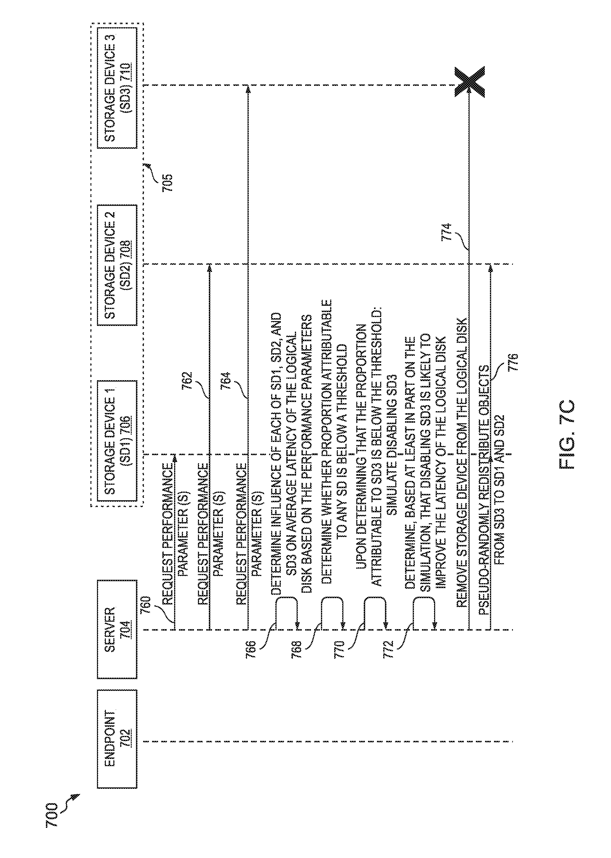
[0010] FIGS. 7A, 7B, 7C and 7D illustrate exemplary data transmissions between components of a system for improving the performance of a logical disk; and
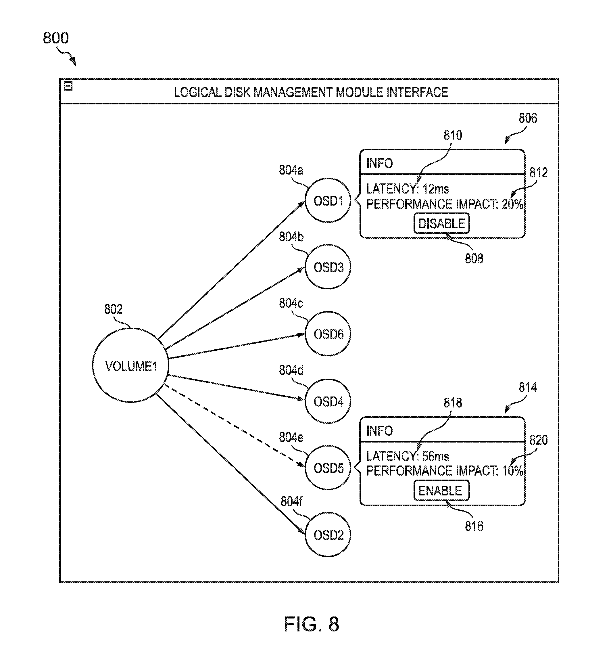
[0011] FIG. 8 is an exemplary graphical interface for a logical disk management module.
DESCRIPTION OF EXAMPLE EMBODIMENTS OF THE DISCLOSURE
Overview
EXAMPLE EMBODIMENTS
[0012] Some file storage systems store each complete and unmodified file in a contiguous block of memory in a storage disk. However, some object storage systems use a process, sometimes referred to as data striping, to split each file into several portions, called objects, before storing them in one or more storage devices. In other words, each object is a fragment of a file (e.g., each fragment being a subdivision of the file). It is noted that the terms `object` and `fragment` are used interchangeable in the present disclosure. In addition, each object may be replicated on more than one storage device. For example, when writing a file, the file is split into objects and each object may be stored on a storage device (a primary storage device) and a copy of the object may be stored on, e.g., one or more other storage devices (redundant storage devices referred to herein as replica storage devices). It is noted that each object of a single file need not have the same storage device as the primary storage device. Indeed, the objects that comprise a single file may be distributed and replicated across 100s of storage devices. When the file is read from the file system, each object is read only from the primary storage device. Thus, reading and writing an object is asymmetric in that reading the object from an object storage system (OSS) only requires accessing a single storage device (i.e., the primary storage device) while writing an object to the OSS requires accessing a several storage devices (i.e., the primary storage device and each of the replica storage devices). In many systems, it is desirable to keep latency down (e.g., low latency is preferred; high latency is undesirable). In general, this asymmetry causes objects to be read faster (e.g., lower latency) than they are written. Reading and writing files causes repeated reading and writing of objects, which further exacerbates the asymmetry.
[0013] An object storage system (OSS) is inclusive of a plurality of object storage devices (OSDs) for storing objects (i.e., the file fragments). An object storage device (OSD) is a storage device (e.g., physical or logical) in which the objects are stored. In many cases, an OSD is a physical storage device (including, e.g., a memory, a processor, a cache) but may also be inclusive of a logical disk (based on several physical devices or partitions of a single physical device). An OSD is a primary storage unit of an OSS. An OSD can include a client (e.g., code, software) that can be executed by an endpoint to access a logical disk using a file system interface. A `logical disk` is inclusive of a virtual storage device that provides access to memory that is located on one or more physical storage devices. For example, a logical disk may include memory from several different physical devices, each of which may be co-located (e.g., in a single data center) or may be remote from another (e.g., in different data centers). In addition, each physical device may have multiple partitions of memory each of which are can be used, by itself, as a logical disk or can be used in combination with memory from other storage devices to form the logical disk.
[0014] One problem that arises in file systems is how to determine the latency of a disk on which the files are stored. Computing latency is trivial for file systems that store files only on a local storage disk. Moreover, such calculations may be unnecessary since the disk is local and the files can be stored in a contiguous block of memory. For file systems that store (all) files of the logical disk in a single remote disk, the latency of the logical disk is simply the latency of the single remote disk. For file systems that store files in multiple remote disks, latency can be determined based on a latency of each remote disk and a weight value that accounts for a proportion of the logical disk stored in each remote disk. For example, the logical disk may store files in two remote disks, where 20 percent of the files of are stored in a first disk and 80 percent of the files are stored in a second disk. In such a case, the latency of the logical disk may be calculated as 0.2*(latency of the first disk)+0.8*(latency of the second disk). However, it is much more complicated to determine the latency of a logical disk for which the data is stored in an object storage system (e.g., based on the asymmetry of the reads/writes of objects) and the large number of storage devices that may be used for a single file. Thus, an objective technical problem is to determine the latency of a logical disk that asymmetrically reads object from and writes objects to the logical disk.
[0015] A file system may utilize an object storage system (OSS) as an underlying data storage system. For example, a service provider (or operator) may provide data storage as a service to endpoints using an OSS. Each endpoint may be associated with an entity (e.g., an individual or an organization). A tenant refers an entity associated with one or more endpoints each of which can receive, as a service from the service provider, access to the file system and/or the OSS. Each endpoint is associated with (e.g., belongs to and/or is operated by) at least one entity. As an example, a company (i.e., an organization that is a tenant of the service provider) may provide each of its employees with a mobile device (i.e., an endpoint). Each endpoint may acquire (e.g., download), from the service provider, a client module (e.g., code, software), which, when executed by the endpoint, generates a file system interface based on objects stored in the OSS. Thus, from the perspective of any endpoint that uses the client module and/or the file system interface to access the file system, the (complete and unmodified) files appear to be stored in a single directory. However, on the backend of the file system, each file is fragmented into objects and is stored across one or more storage devices.
[0016] The term `endpoint` is inclusive of devices used to initiate a communication, such as a computer, a personal digital assistant (PDA), a laptop or electronic notebook, a cellular telephone (e.g., an IPHONE, an IP phone, a BLACKBERRY, a GOOGLE DROID), a tablet (e.g., an IPAD), or any other device, component, element, network element, or object capable of initiating voice, audio, video, media, and/or data exchanges within system 100 (described below). An endpoint may also be inclusive of a suitable interface to the human user, such as a microphone, a display, or a keyboard or other terminal equipment. An endpoint may also be any device that seeks to initiate a communication on behalf of another entity or element, such as a program, a conferencing device, a database, or any other component, device, element, or object capable of initiating an exchange within the system 100. Furthermore, endpoints can be associated with individuals, clients, customers, or end users. Data, as used herein in this document, refers to any type of numeric, voice, messages, video, media, or script data, or any type of source or object code, or any other suitable information in any appropriate format that may be communicated from one point to another.
[0017] FIG. 1 illustrates an object storage system (OSS) used as a data storage system that underlies a file system. In particular, FIG. 1 illustrates, among other things, a system (i.e., system 100) comprising an object storage system (OSS) in which fragments of a file (i.e., objects) are stored in logical disks. The system 100 comprises tenants 102 and 106, file system interfaces 110 and 112, files 116 and 122, network 118, and data center 124. Each of the tenants 102 and 106 comprise a plurality of endpoints 104. The tenant 102 comprises endpoints 104a, 104b, 104c, and 104d. The tenant 106 comprises endpoints 104e, 104f, 104g, 104h, and 104i. Each of the endpoints 104a-104i (collectively referred to as endpoints 104) can access logical disks via a file system client interface (i.e., file system client interfaces 110 and 114). The endpoints 104 utilize the file system interfaces 110 or 112 to access (over the network 118) the files (e.g., files 116 or 112) from logical disks in the data center 124. The data center 124 comprises a network element 124 coupled to each of storage devices 132a-e. Each of the storage devices 132a-e is a physical storage device and is an object storage device (OSD) in the OSS. Each of the storage devices 132a-e is associated with one or more of logical disks 128 and 130. Fragments of the files are stored distributed across the storage devices 132a-e, which make up logical disks 128 and 130. Each of the logical disks stores fragments of a file in a primary storage device (within the logical disk) and one or more replica storage devices (within the same logical disk). In contrast, each the logical disks retrieves the fragments from the primary storage device and not the one or more replica storage devices. Thus, each logical disk asymmetrically stores fragments in and retrieves fragments from logical disks (e.g., based, at least in part, on retrieving a fragment from the logical drive accesses the storage devices a different number of times than for writing the fragment to the logical drive). It is noted that the data center 124 is illustrated with five storage devices (i.e., 132a-e) only for clarity and simplicity of the figures. In practice, the data center 124 may include any number of storage devices (in some cases of thousands of storage devices).
[0018] The network 118 operatively couples the tenants (i.e., 102 and 106) and the data center 124 to one another. The network 118 facilitates two-way communication between any two or more of the components of system 100. For example, each of the endpoints 104 can transmit to and/or receive data from the data center 124 (e.g., the network element 124, logical disks 128 and 138, and/or storage devices 132a-e therein) over the network 118. Within the context of the disclosure, a `network` represents a series of points, nodes, or network elements of interconnected communication paths for receiving and transmitting packets of information that propagate through a communication system. A network offers communicative interface between sources and/or hosts, and may be any local area network (LAN), wireless local area network (WLAN), metropolitan area network (MAN), Intranet, Extranet, Internet, WAN, virtual private network (VPN), or any other appropriate architecture or system that facilitates communications in a network environment depending on the network topology. A network can comprise any number of hardware or software elements coupled to (and in communication with) each other through a communications medium.
[0019] The data center 124 comprises a network element 126 and a plurality of storage devices 132a-132e. The network element 126 and each of the plurality of storage devices 132a-132e are operably coupled to one another by communication channels. The data center 124 includes two logical disks: logical disk 128 and logical disk 130. The logical disks 128 and 130 are associated with at with tenants 120 and 106 respectively. Each tenant is provided with access only to its logical disks (and not to logical disks that are associated with other tenants). The network element 126 may maintain metadata associated with the logical disks. In this example, each tenant is associated with a single logical disk only for clarity of the figures. Each tenant may be associated with any number of logical disks. The metadata may include data mappings that, at least in part, define the logical disks and identify a manner in which the logical disk operates. For example, the network element 126 can store data comprising: a mapping of each storage device to one or more logical disks, a mapping of each tenant to one or more logical disks; a mapping of each tenant to one or more storage devices; a mapping of each logical disk to operational variables that identify a manner in which a logical disk operates. The operational variable may include (but are not limited to): a size of each object to be stored in the logical disk (e.g., measured in bit or multiples thereof), a number of primary storage devices in which each object is to be stored, a number of replica storage devices in which each object is to be stored, pools of storage devices (e.g., subgroups of storage devices within a logical disk) for which one of the storage devices is primary storage device and others of the storage devices are replica storage devices, and/or any other parameters that define (or otherwise specify) a manner in which a logical disk operates. In this example, each of the storage devices 132a, 132b, and 132c is mapped to logical disk 128; each of the storage devices 132c, 132d, and 132e is mapped to logical disk 130; the tenant 102 is mapped to the logical disk 128; the tenant 106 is mapped to the logical disk 130; the logical disk 128 is associated with operational variables including: a fragment size of three bits, one primary storage device for each fragment, two replica storage devices for each fragment; and the logical disk 130 is associated with operational variables including: a fragment size of four bits, one primary storage device for each fragment, and one replica storage device for each fragment. It is noted that each logical disk may be mapped to a single logical disk or to multiple logical disks. In this example, the logical disks 128 and 130 share the storage device 132c.
[0020] As used herein in this Specification, the term `network element` is meant to encompass any as servers (physical or virtual), end user devices, routers, switches, cable boxes, gateways, bridges, load balancers, firewalls, inline service nodes, proxies, processors, modules, or any other suitable device, component, element, proprietary appliance, or object operable to exchange, receive, and/or transmit data in a network environment. These network elements may include any suitable hardware, software, components, modules, interfaces, or objects that facilitate the sharing of message queue operations thereof. This may be inclusive of appropriate algorithms and communication protocols that allow for the effective exchange of data or information. Each of the network elements can also include suitable network interfaces for receiving, transmitting, and/or otherwise communicating data or information in a network environment.
[0021] In one particular instance, the architecture of the present disclosure can be associated with a service provider deployment. For example, a service provider (e.g., operating the data center 124) may provide the tenants 102 and 106 with access to logical disks 128 and 130 in the data center 124. In other examples, the architecture of the present disclosure would be equally applicable to other communication environments, such as an enterprise wide area network (WAN) deployment. The architecture of the present disclosure may include a configuration capable of transmission control protocol/internet protocol (TCP/IP) communications for the transmission and/or reception of packets in a network.
[0022] The dashed lines between the network 118 and the tenants 102 and 106 (and the endpoints 104 therein) and the data center 124 represent communication channels. As used herein, a `communication channel` encompasses a physical transmission medium (e.g., a wire) or a logical connection (e.g., a radio channel) used to convey information signals (e.g., data, data packets, control packets, messages etc.) from one or more senders (e.g., an tenant, an endpoint, a network element, a storage device, and the like) to one or more receivers (e.g., a second data center, a second message queue, a message consumer, a network element, and the like). Data, as used herein, refers to any type of source or object code, object, fragment of a file, data structure, any type of numeric, voice, messages, video, media, or script data packet, or any other suitable information in any appropriate format that may be communicated from one point to another. A communication channel, as used herein, can include one or more communication links, which may be physical (e.g., wire) or logical (e.g., data link, wireless link, etc.). Termination points of communication channels can include network interfaces such as Ethernet ports, serial ports, etc. In some examples, each communication channel may be a single channel: deployed for both control messages (i.e., instructions to control a network element, a logical disk, and/or a storage device) and data messages (i.e., messages that include objects for storage in one or more storage devices).
[0023] The file system interfaces 110 and 112 are a graphical user interface for the file system that stores files in logical disks 128 and 130 (respectively) in the data center 124. Each of the endpoints 104 executes a code block to generate the file system Interface (i.e., interface 110 or 112) through which the endpoint can access the files in the file system. Each of the tenants is provided with access to one or more logical disks in the data center. Tenants have a corresponding customized file system interface through which to access to their logical disks (e.g., the interfaces are customized on a per-tenant basis). The file system interface 110 renders filenames (i.e., filenames "FILE 1", "FILE 2", . . . , "FILE n") for a directory location in the logical disk 128 associated with the tenant 102. The file system Interface 112 renders filenames (i.e., filenames "FILE A", "FILE B", . . . , "FILE m") for a directory location in the logical disk 130 associated with the tenant 106. Each of the filenames corresponds to a file. The filename 114 corresponds to file 116. The filename 120 corresponds to file 122. Within the file system interfaces 110 and 112, files appear to be complete, unmodified, and stored in a single directory. Thus, from the perspective of any of the endpoints 104 that use the file system interface, the (complete and unmodified) files appear to be stored in a single directory. However, within the data center 124, each file is fragmented into objects and is stored across one or more storage devices.
[0024] For example, each of the files 116 and 122 is fragmented into objects; the objects are stored distributed and replicated across several storage devices in a logical disk. The file 116 is named "FILE 1" and corresponds to the filename 114 in the file system interface 110. The file 122 is named "FILE A" and corresponds to the filename 120 in the file system interface 112. Each of the files 116 and 122 is stored, at least in part, in binary form. The files may be further encoded in a standardized encoding (e.g., ASCII, Unicode, BinHex, Uuencode, Multipurpose Internet Mail Extensions (MIME), multimedia encoding such as audio and/or video encoding) or a propriety encoding (e.g., a proprietary file type generated by proprietary software). The files are split into objects. Each object is a fragment of the file. A size of the objects (e.g., measured in bit, bytes, or any multiple thereof) is configurable (e.g., by an endpoint, a network element, and/or other computing element with administrative rights). Thus, each service provider, each tenant, each endpoint, and the like may customize the size of the object. In the example of system 100, one of the endpoints 104a-d has set the size of the object to 3 bits for all files associated with the tenant 102; one of the endpoints 104e-i has set the size of the object to 4 bits for all files associated with the tenant 106. The files 116 and 122 are split into objects based, at least in part, on the size of the object set for the corresponding tenant. The file 116 (i.e., "FILE 1") is split into five 3-bit objects (labeled "F1.1", "F1.2", "F1.3", "F1.4", and "F1.5"). The file 122 (i.e., "FILE A") is split into three 4-bit objects (labeled "FA.1", "FA.2", and "FA.3"). Each object (i.e., each fragment of the file) is asymmetrically stored in and retrieved from storage devices in the data center 124.
[0025] Each fragment of a file is asymmetrically stored in and retrieved from storage devices in the data center 124. Each fragment being stored in multiple storage devices makes the logical disk robust. A failure of any of the storage devices is less likely to cause a complete loss of any file or fragment thereof at least because each fragment is redundantly stored in multiples storage devices. If a storage device fails, copies of fragments stored on others of the storage devices can be used to reassign a primary and/or additional replica storage devices as needed. Each fragment is assigned a primary storage device and one or more replica storage devices from the storage devices associated with a logical disk. A primary storage device stores its assigned fragments and, when they are requested from the logical disk, the primary storage device retrieves the assigned fragments and transmits them to the requesting component. A replica storage device stores its assigned fragments and but is not responsible for retrieving the assigned fragments in response to requests. In other words, while the each fragment is stored in multiple storage devices (i.e., the primary and the replica storage devices) only one of the multiple storage devices responds to requests to read the fragment. Writing a fragment to the logical disk requires activity from several storage devices (i.e., the primary storage device and each of the replica storage devices) while reading the fragment from the logical disk only requires activity from the a single storage device (i.e., the primary storage device). Retrieving an object from the logical drive accesses the storage devices a different number of times than for writing the object to the logical drive.
[0026] Each object is stored in a primary storage device and one or more replica storage devices. In FIG. 1, the object, when stored in the primary storage device, is illustrated as a solid rectangle and, when stored in the replica storage devices, is illustrated as a dashed or dotted rectangle. A first copy of each object is labeled with a prime symbol ('); a second copy of each object is labeled with a double prime symbol (''). The file 116 (i.e., "FILE 1") is split into five 3-bit objects (labeled "F1.1", "F1.2", "F1.3", "F1.4", and "F1.5") and stored in the logical disk 128. The logical disk 128 comprises storage disks 132a and 132b and at least a portion of the storage disk 132c. Each object of File 1 is stored in a primary storage device and two replica storage devices. For example, for the object F1.1, the storage device 132a is the primary storage device (storing the object F1.1); the storage device 132b is a first replica storage device (storing the first copy F1.1'); and the storage device 132c is a second replica storage device (storing the first copy F1.1''). Table 1 below summarizes the primary storage devices and replica storage devices for each of the objects parsed from the FILE 1.
TABLE-US-00001 TABLE 1 Summary of primary storage devices and replica storage devices in the logical disk 128 for each of the objects parsed from the FILE 1. First Second Object Primary Replica Replica F1.1 132a 132b 132c F1.2 132b 132c 132a F1.3 132c 132a 132b F1.4 132a 132b 132c F1.5 132b 132c 132a
[0027] The file 122 (i.e., "FILE A") is split into three 4-bit objects (labeled "FA.1", "FA.2", and "FA.3") and stored in the logical disk 130. The logical disk 130 comprises storage disks 132d and 132e and at least a portion of the storage disk 132c. Each object of File A is stored in a primary storage device and a replica storage device. For example, for the object FA.1, the storage device 132c is the primary storage device (storing the object FA.1); and the storage device 132e is a first replica storage device (storing the first copy FA.1'). Table 2 below summarizes the primary storage devices and replica storage devices for each of the objects parsed from the FILE A.
TABLE-US-00002 TABLE 2 Summary of primary storage devices and replica storage devices in the logical disk 130 for each of the objects parsed from the FILE A. First Object Primary Replica FA.1 132c 132e FA.2 132d 132c FA.3 132e 132d
[0028] As discussed above, an objective technical problem is to determine the latency of a logical disk that asymmetrically reads and writes objects, as is the case for logical disks 128 and 130. The following is a practical example of such a problem. In a cloud computing environment (e.g., the cloud computing software marked under the trade name OpenStack) with an object storage system (e.g., the storage system marketed under the trade name CEPH) as the backend storage, it is common for an operator (e.g., a service provider) to have difficulties identifying a reason why a tenant's logical disk (e.g., a Ceph volume) is "slow" (i.e., read and/or write operations to the logical disk have a latency that negatively impacts performance of the system and/or is unacceptable to the tenant). When a tenant reports, to the operator, that their logical disk is slow, operators are neither able to validate the report nor identify the reasons for the logical disk being slow. Because the logical disk volume is distributed across potentially thousands of physical disks (e.g., storage devices), isolating the problem to one or more disks can be a challenge.
[0029] A potential solution is to empirically determine the latency of a disk. In traditional distributed storage systems, latency can be calculated through experiments based on request and response (completion) of events. This method of latency calculation cannot be applied to determine latency of a logical disk (such as logical disks 128 and 130 of FIG. 1) because the entire logical disk is not read from or written to a single physical disk. Also, calculating latency of a logical disk in object-based storage (e.g., in object storage systems) is challenging because there may be multiple objects belonging to a same logical disk stored in a same storage device. In other words, if all of the objects were retrieved from the logical disk, some of the storage devices would have to retrieve more objects than others of the storage devices. Thus, the storage devices that perform more retrieving would have a higher influence on the performance of the logical disk than the others of the storage devices. Another possible solution is to manually debug a logical disk by manually inspecting each of the associated storage devices to identify any latency issues; this is time consuming, inefficient, and prone to errors and oversights.
[0030] A solution, disclosed in the present disclosure, to address the above issues (and others) provides for improving performance of a logical disk by reconfiguring storage devices in the logical disk based on asymmetric reading and writing characteristics of the storage devices. The methods, systems, logic, and/or apparatuses (as disclosed herein) address the above technical problem (and others) by adding and/or removing storage devices from the logical disk based on an influence that each of the exiting storage devices in the logical disk has on the overall performance of the logical disk. In some examples, the methods, systems, logic, and/or apparatuses disclosed herein utilize a number of objects that a storage device is associated with retrieving and a different number of objects that the storage device is associated with storing to determine the influence on the logical disk. In addition, the adding or removing of the storage device can be simulated using a mathematical model of the logical disk to verify whether the addition or removal (as the case may be) of the storage device will improve the performance of the logical disk.
[0031] FIG. 2 is a simplified diagram of details of the network element 126 and storage devices 132a-c in the data center 124 implementing the object storage system (OSS) of FIG. 1. FIG. 2 illustrates a portion of the storage devices 132 (i.e., illustrates storage devices 132a-c and not storage devices 132d-e) only clarity of the Figure.
[0032] The network element 126 of FIG. 2 is an example of the network element 126 of FIG. 1 and/or of the server 704 (of FIGS. 7A-7D, which are described below). The network element 126 comprises a processor 202, a memory element 204, a data bus 208, a network interface 210, and a logical disk management module 214. The data bus 208 operably couples the components to one another. The network interface 210 includes a plurality of ports 212, each of which is configured to transmit and/or receive data over a network. The memory element 204 stores, among other things, logical disk metadata 206 and a distributed storage code block 207. The logical disk metadata 206 is inclusive of the mappings (defining the logical disks and/or identifying a manner in which the logical disk operates) described with respect to FIG. 1, the data of Table 1 (of the present disclosure), the data of Table 2 (of the present disclosure), and/or the data of FIG. 3 (which is described below). The processor 202, among other things, executes the distributed storage code block 207 that, at least in part defines and manages an object storage system in the data center 124. When executed, the distributed storage code block 207, can generate control plane messages for communication with corresponding distributed storage code blocks in other components of the logical disk (e.g., distributed storage code block 226a-c in the storage devices 132a-c). Moreover, each distributed storage code block the logical disk may include libraries of functions to operate the OSS (e.g., algorithms for pseudo-randomly distributing objects and copies to storage devices, data striping algorithms for fragmenting a file into objects, and the like). As an example, a distributed storage code block may be client, a daemon, or an operating system for the device to operate within the object storage system. As a further example, each distributed storage code block may be a CEPH daemon (e.g., a Cluster monitor daemon, a metadata server daemon, an object storage device daemon). In such an example, the distributed storage code block 207 may be a metadata server daemon and each of the distributed storage code block 226a-c may be an object storage device daemon. In addition, the processor 202 executes code corresponding to the logical disk management module 214 and accesses data from the memory element 204 to manage, using the code, a logical disk and improve its performance by exploiting the asymmetric reading and writing characteristics of the storage devices of the logical disk. The logical disk management module 214 (and the corresponding code) includes logic for improving the performance of a logical disk.
[0033] Each of the storage devices 132a-c comprises respective processors 216a-c, network interfaces 218a-c, and memory elements 222a-c. Each of the network interfaces 218a-c includes a respective plurality of ports 220a-c, each of which is configured to transmit and/or receive data over a network. Each of the memory elements 222a-c stores, among other things, a distributed storage code block 226a-c. The processors 216 execute the distributed storage code blocks 226a, which, at least in part, define and manage an object storage system in the data center 124. When executed, each of the distributed storage code blocks 216a-c, can generate control plane messages for communication with corresponding distributed storage code blocks in other components of the logical disk (e.g., distributed storage code block 207 in the network element 126). Moreover, each distributed storage code block the logical disk may include libraries of functions to operate the OSS (e.g., algorithms for distributing objects to storage devices and/or copying objects to replica storage devices). Each of the storage devices 132a-c has a portion of their memory element dedicated to storing objects. Storage device 132a include memory portion 224a, which stores objects (and copies of objects) associated with files stored in the logical disk 128 of FIG. 1. Storage device 132b include memory portion 224b, which stores objects (and copies of objects) associated with files stored in the logical disk 128 of FIG. 1. Storage device 132c include memory portion 224c, which stores objects (and copies of objects) associated with files stored in the logical disk 128 of FIG. 1. The details of the objects and the copies stored in the logical disk 128 are provided in the Table 1 and the corresponding description; the details are omitted here only for the purpose of brevity of the specification.
[0034] FIG. 3 is a simplified schematic diagram of logical disk metadata. In this example, the metadata is a table that identifies, for each of a plurality of storage devices, at least one impact factor. The columns of the table 300 include column 302 identifying a logical disk identifier (ID); column 304 identifying a storage device ID; column 306 identifying a read impact factor for the corresponding combination of the logical disk ID and the storage device ID; column 308 identifying a write impact factor the corresponding combination of the logical disk ID and the storage device ID; and column 310 identifying a latency for the corresponding storage device ID (measured in milliseconds, ms).
[0035] The table 300 includes metadata corresponding to the storage devices 132a-e and the logical disks 128 and 130 in the data center 124 of FIG. 1. In particular, the logical disk 128 corresponds to the logical disk ID "1"; the logical disk 130 corresponds to the logical disk ID "2"; the storage device 132a corresponds to the storage device ID "1"; the storage device 132b corresponds to the storage device ID "2"; the storage device 132c corresponds to the storage device ID "3"; the storage device 132d corresponds to the storage device ID "4"; and the storage device 132e corresponds to the storage device ID "5".
[0036] The row 312 corresponds to metadata associated with the storage device ID 1 (i.e., the storage device 132a) within the context of the logical disk ID 1 (i.e., the logical disk 128). The row 314 corresponds to metadata associated with the storage device ID 2 (i.e., the storage device 132b) within the context of the logical disk ID 1 (i.e., the logical disk 128). The row 316 corresponds to metadata associated with the storage device ID 3 (i.e., the storage device 132c) within the context of the logical disk ID 1 (i.e., the logical disk 128). The row 318 corresponds to metadata associated with the storage device ID 3 (i.e., the storage device 132c) within the context of the logical disk ID 2 (i.e., the logical disk 130). The row 320 corresponds to metadata associated with the storage device ID 4 (i.e., the storage device 132d) within the context of the logical disk ID 2 (i.e., the logical disk 130). The row 322 corresponds to metadata associated with the storage device ID 5 (i.e., the storage device 132e) within the context of the logical disk ID 2 (i.e., the logical disk 130).
[0037] Each of the rows of the table 300 identifies a combination of a logical disk ID and a storage device ID and corresponding performance parameters for the combination. The rows identify the combination of the logical disk ID and the storage device ID at least because each storage device may be associated with more than one logical disk. For example, the storage device ID 3 (i.e., the storage device 132c) is associated with both the logical disk IDs 1 and 2 (i.e., the logical disks 128 and 130, respectively) and, as a result, the table 300 contains two rows (i.e., rows 316 and 318) that identify the metadata for the storage device ID 3: one for each of the logical disk IDs 1 and 2.
[0038] Each impact factor identifies, on a per logical disk basis, a proportion of objects stored in or retrieved from each of the plurality of storage devices relative to others of the plurality of storage devices based on asymmetrical storage in and retrieval from each of the plurality of storage devices. The impact factors correspond to an influence that each of the storage devices has on the performance (e.g., average latency, amount of throughput, and the like) of the logical disks to which the storage device is associated. For example, as the amount of throughput (e.g., a computational load) on each storage device increases, the latency of each storage device increases because it takes more the time to process each read/write request than if the amount of throughput were reduced.
[0039] A network element (e.g., a server, such as a metadata server in a CEPH system), may calculate the impact factors by, at least in part, counting a number of objects for which each of the plurality of storage devices is a primary storage device and/or a replica storage device.
[0040] The read impact factor (i.e., in column 306) identifies a number of objects for which each of the storage devices is a primary storage device within the context of a logical disk. The network element may calculate the read impact factor based on metadata associated with the logical disk and/or data retrieved from the storage devices. For example, the network element may utilize metadata including the data of Tables 1 and 2 of the present disclosure to count the number of objects for which each of the storage devices is a primary storage device within the context of a logical disk. In other examples, the network element may transmit to each storage device in a logical disk a request for a read impact factor. The request for the read impact factor may be for a single file, multiple files, or for all files for which the storage device stores objects (based on identifiers of files and/or objects in the request). The request may also identify a particular logical disk for which the impact factor is requested (e.g., since the impact factor may be different for each logical disk to which the storage device is associated).
[0041] Assuming, only for the sake of an simple example, that each logical disk only stores a single file (e.g., FILE 1 or File A), the read impact factor for each device is the number times that the storage device is identified in the column labeled "Primary" in Tables 1 and 2 (i.e., the number of objects for which the device is the primary storage device, which responds to read requests for the object). Table 1 includes metadata for the logical disk 128 (logical disk ID 1 in FIG. 3). The storage device 132a (storage device ID 1 in Table 300 of FIG. 3) is listed twice in the "Primary" column in Table 1 (for objects F1.1 and F1.4), which corresponds to the read impact factor of 2 in row 312 of table 300 in FIG. 3. The storage device 132b (storage device ID 2 in Table 300 of FIG. 3) is listed twice in the "Primary" column in Table 1 (for objects F1.2 and F1.5), which corresponds to the read impact factor of 2 in row 314 of table 300 in FIG. 3. The storage device 132c (storage device ID 3 in Table 300 of FIG. 3) is listed once in the "Primary" column in Table 1 (for objects F1.3), which corresponds to the read impact factor of 1 in row 316 of table 300 in FIG. 3. Table 2 includes metadata for the logical disk 130 (logical disk ID 2 in FIG. 3). The storage device 132c (storage device ID 3 in table 300 of FIG. 3) is listed once in the "Primary" column in Table 2 (for objects FA.1), which corresponds to the read impact factor of 1 in row 318 of table 300 in FIG. 3. The read impact factors of 1 in rows 320 and 322 of table 300 (for storage devices 132d and 132e (storage device IDs 4 and 5), respectively) are calculated in a manner similar to that for row 318.
[0042] The above process is described with respect to calculating the read impact factor of various storage devices for a single file. Object storage systems often store many files. The impact factor for all of the files in the logical disk may be calculating by repeating, for each file in the logical disk, the above-described process of calculating impact factors for a single file. The overall read impact factor for each storage devices in the logical disk may be calculated by summing the individual read impact factors (for each file) for each storage device to determine.
[0043] The write impact factor (i.e., in column 308) identifies a sum of: a first number of objects for which each of the storage devices is a primary storage device, and a second number of objects for which each of the storage devices is a replica storage device. A network element may calculate the write impact factor based on metadata associated with the logical disk and/or data retrieved from the storage devices. For example, the network element may utilize metadata including the data of Tables 1 and 2 of the present disclosure to count the number of objects for which each of the storage devices is a primary storage device and the number of objects for which each of the storage devices is a replica storage device within the context of a logical disk. In other examples, the network element may transmit to each storage device in a logical disk a request for a write impact factor. The request for the write impact factor may be for a single file, multiple files, or for all files for which the storage device stores objects (based on identifiers of files and/or objects in the request). The request may also identify a particular logical disk for which the impact factor is requested (e.g., since the impact factor may be different for each logical disk to which the storage device is associated).
[0044] The following example assumes (only for the sake of a simple example) that each logical disk only stores a single file (e.g., FILE 1 or File A). In such an example, the write impact factor for each device is the sum of (1) a number times that the storage device is identified in the column labeled "Primary" in Tables 1 and 2 (i.e., the number of objects for which the device is the primary storage device), and (2) a number times that the storage device is identified in any of the remaining "Replica" columns in Tables 1 and 2 (i.e., the number of objects for which the device is a replica storage device, which responds to write requests for the object). Table 1 includes metadata for the logical disk 128 (logical disk ID 1 in FIG. 3). The storage device 132a (storage device ID 1 in table 300 of FIG. 3) is listed twice in the "Primary" column in Table 1 (for objects F1.1 and F1.4) and is listed thee times in the "Replica" columns in Table 1 (first replica for object F1.3 and second replica for objects F1.2 and F1.5); this corresponds to the write impact factor of (2+3) 5 in row 312 of table 300 in FIG. 3. The write impact factors of 5 in rows 314 and 316 of table 300 (for storage devices 132b and 132c (storage device IDs 2 and 3), respectively) are calculated in a manner similar to that for row 312. Table 2 includes metadata for the logical disk 130 (logical disk ID 2 in FIG. 3). The storage device 132c (storage device ID 3 in table 300 of FIG. 3) is listed once in the "Primary" column in Table 2 (for objects FA.1) and is listed once in the "Replica" column in Table 2 (for object FA.2); this corresponds to the write impact factor of (1+1) 2 in row 318 of table 300 in FIG. 3; this corresponds to the read impact factor of 1 in row 318 of table 300 in FIG. 3. The read impact factors of 1 in rows 320 and 322 of table 300 of table 300 (for storage devices 132d and 132e (storage device IDs 4 and 5), respectively) are calculated in a manner similar to that for row 318.
[0045] The impact factors are attributes that can be used to determine the influence that each storage device has on a logical disk by accounting for asymmetric read and write operations of the storage device. Other attributes may be used to determine the influence that each storage device has on a logical disk. Other attributes may include (but are not limited to) any one or more of the following attributes of a storage device: a number of pending operations (e.g., a number of operations in a queue of operations to be performed by the storage device), a number of stored objects (e.g., a total number of objects stored by the storage device across all of the logical disks with which it is associated), total number of logical disks using the storage device, and/or system metrics (e.g., performance parameters, a latency of input/output ("I/O") operations measured during a window of time, current processor utilization, current memory utilization, and the like). For example, as the current utilization of the processor (e.g., percent of processor capacity utilized by currently executing processes) increases for each storage device, the influence that each storage device has on latency of the logical disk increases because it takes more the time for each storage device to process each read/write request than if the current utilization were reduced.
[0046] The attributes may be requested directly from each storage device or may be calculated. In the example of latency, a latency of I/O operations performed by a storage device may be calculated by dividing a number of operations performed by the storage device (during in a window of time) divided by the length of time interval (e.g., measured seconds, minutes, or multiples thereof) to get average latency of the I/O operations. In some examples, the window of time is a moving time window (e.g., a most recent window of 15 minutes, 30 minutes, 1 hour, and the like).
[0047] After the attributes are collected for (e.g., calculated and/or retrieved from) each of the storage devices in a logical disk known, a numerical representation of an influence that each storage device has on operational performance the logical disk is determined. The numerical representation corresponds to a proportion of the operational performance of the logical device that is attributable to each of the plurality of storage devices based, at least in part, on the attributes of each of the storage devices. The numerical representation of the influence of each storage device may be determined using a mathematical model. In some examples, the numerical representation is a weighting factor for each of the plurality of storage devices.
[0048] A weighting factor for each of the storage devices can be calculated based one or more of the attributes of the each of the storage devices. The weighing factors may be percentage values that correspond to the asymmetric reading and writing characteristics of the storage devices of the logical disk. A weighting factor for a storage device is determined, at least in part, based on an impact factor of the storage device. In some examples, the weighting factor is determined based only on the impact factor(s). The following illustrates example calculations for determining the weighting factors is determined based only on impact factors. Weighting factors are calculated in the context of a logical disk (e.g., on a per-logical disk basis). Returning to table 300 of FIG. 3, the rows 312, 314, and 316 identify metadata for the logical disk ID 1 (logical disk 128 of FIG. 1) and the rows 318, 320, and 322 identify metadata for the logical disk ID 2 (logical disk 130 of FIG. 1). Example weighting factors (e.g., percentage values) for the logical disk ID 1 can be determined by dividing each impact factor by the sum of all of the impact factors (i.e., summing all of the read and write impact factors together ting factors). The sum of all of the read and write impact factors for logical disk ID 1 is 2+2+1+5+5+5=20 (the logical disk sum). The sum of the read and write impact factors for a storage device is divided by the logical disk sum to determine the weighting factor. Thus, the weighting factor for the storage device ID 1 (i.e., row 312) is (2+5)/20=7/20=0.35 (i.e. the sum of the read impact factor and the write impact factor, divided by logical disk sum). The weighting factor for the storage device ID 2 (i.e., row 314) is (2+5)/20=7/20=0.35. The weighting factor for the storage device ID 3 (i.e., row 316) is (1+5)/20=6/20=0.3. Similarly, the sum of all of the read and write impact factors for logical disk ID 2 is 1+1+1+2+2+2=9 (the logical disk sum). The weighting factor for the storage device ID 3 (i.e., row 318) is (1+2)/9=3/9 0.333. The weighting factor for the storage device ID 4 (i.e., row 320) is (1+2)/9=3/9=0.333. The weighting factor for the storage device ID 5 (i.e., row 322) is (1+2)/9=3/9=0.333. In this example, the weighting factor is a proportion of all of the impact factors (for the logical disk) that is attributable to each storage device (e.g., for each logical disk, sum of the weighing factors is equal to 1). The weighting factors are summarized in Table 3 below.
TABLE-US-00003 TABLE 3 Summary of weighting factors for storage devices in Logical Disk IDs 1 and 2. Logical Storage Weighting Disk ID Device ID Factor 1 1 0.35 1 2 0.35 1 3 0.3 2 3 0.333 2 4 0.333 2 5 0.333
[0049] In other examples, the weighting factor is determined based on the impact factor(s) in combination with one or more other attributes. For example, a mathematical algorithm (e.g., regression algorithm performing a regression analysis) may be executed on impact factor in combination with one or more other attributes to determine weighting factors for the storage device. As a further example, a simulation may be executed be under various conditions of storage disks (e.g., various pseudo-random distributions of objects across the of storage disks, various numbers of pending operations, and various system metrics). A (theoretical) latency of the logical disk can be determined from such simulations. A regression algorithm may take as input: (1) independent variables or factors (e.g., impact factor(s), number of pending operations, number of stored objects, system metrics, and the like) and dependent variables such as a latency of a logical disk (i.e., determined based on the simulations). The regression algorithm may generate, as output, weights to satisfy the following equation for latency of a logical disk (LDLatency):
[0050] LDLatency=sum[WF(i)*LS(i)], for i=1, 2, . . . , n; where n is the number of storage devices in the Logical Disk
[0051] Where LS(i) and the latency of the ith storage device;
[0052] WF is the weighting factor for the storage device;
[0053] WF=sum[x(j)*f(j)], for j=1, 2, . . . , m; where m is the number of factors input for the storage devices; and
[0054] f(j) is the jth factor for the storage device (e.g., factors such as impact factor(s), number of pending operations, number of stored objects, system metrics, and the like)
[0055] x(j) is the jth weight associated with the jth factor.
[0056] The regression algorithm is utilized to generate the weights (i.e., x(j)). Once the weights are known, they are used to determine LDLatency in a production environment (for actual storage devices and not simulated storage devices). The mathematical algorithm can be executed on the fly (e.g., in near real-time) and at regular intervals to track the influence of a storage device over time.
[0057] The above examples of calculating the weighting factors are provided for illustration purposes only (and do not limit the teaching of the present disclosure). Indeed, the teachings of the present disclosure are equally applicable to any approach of calculating the weighting factors as long as the approach accounts for the asymmetric reading and writing characteristics of the storage devices of the logical disk, as is demonstrated by the above exemplary approaches.
[0058] A portion of a performance parameter of a logical device that is attributable to each storage device in the logical device is calculated based, at least in part, on a corresponding performance parameter of each storage device weighted by the corresponding influence. In the example of latency, a weighted latency for a storage device can be calculated based on latency of I/O operations of the storage device and the weighting factor for the storage device. The weighted latency of the storage device is a portion of latency of the logical disks that is attributable to the storage device. For example, the weighted latency of the storage device (WLatency) is calculated by multiplied the weighting factor for the storage device (WF) and the latency of the storage device (LS) (i.e., WLatency=WF*LS). In some examples, the latency of the storage device (LS) is the latency of the I/O operations measured during a window of time. A calculation can be performed for each of a plurality of plurality of storage devices comprising logical disk. In such an example, for each of the plurality of storage devices, the latency of the I/O operations is multiplied by the weighting factor to determine a weighted latency for each of the plurality of storage devices. Table 300 (in FIG. 1) lists, in column 310, an average latency for each of the storage device. The weighted latency for each of the storage devices can be calculated by multiplying the average latency (from table 300) of each storage device by the corresponding weighting factors (from table 3). The weighted latency for the storage device ID 1 (i.e., row 312 of table 300 in FIG. 1) is 11 ms*0.35=3.85 ms. The weighted latency for the storage device ID 2 (i.e., row 314 of table 300 in FIG. 1) is 14 ms*0.35=4.9 ms. The weighted latency for the storage device ID 3 within logical disk ID 1 (i.e., row 316 of table 300 in FIG. 1) is 16 ms*0.3=4.8 ms. The weighted latency for the storage device ID 3 within logical disk ID 2 (i.e., row 318 of table 300 in FIG. 1) is 16 ms*(1/3)=5.333 ms. The weighted latency for the storage device ID 4 (i.e., row 320 of table 300 in FIG. 1) is 9 ms*(1/3)=3 ms. The weighted latency for the storage device ID 5 (i.e., row 322 of table 300 in FIG. 1) is 4 ms*(1/3) 1.333 ms. The weighted latencies are summarized in Table 4 below.
TABLE-US-00004 TABLE 4 Summary of weighted latencies for storage devices in Logical Disk IDs 1 and 2. Logical Storage Weighted Disk ID Device ID Latency (ms) 1 1 3.85 1 2 4.9 1 3 4.8 2 3 5.333 2 4 3.0 2 5 1.333
[0059] A performance parameter of a logical disk can be calculated based, at least in part, on corresponding performance parameters each of the storage devices and the weighting factor. Thus, the performance parameter of the logical disk can be calculated by summing the weighted performance parameter for each of the plurality of storage devices in the logical disk. In one example, a latency of the logical disk is calculated by summing the weighted latency for each of the plurality of storage devices in the logical disk. Thus, the latency of a logical disk=sum[W(i)*Latency(i)] (for i=1, 2, . . . , n; where n is the number of storage devices in the Logical Disk). For example, the logical disk ID 1 (rows 312, 314, and 316 of FIG. 1) has a calculated latency equal to the sum of the corresponding weighted latencies in table 4; the calculated latency of the logical disk ID 1 is (3.85 ms+4.8 ms+4.9 ms)=13.55 ms. The logical disk ID 2 (rows 318, 320, and 322 of FIG. 1) has a calculated latency equal to the sum of the corresponding weighted latencies in table 4; the calculated latency of the logical disk ID 2 is (5.333 ms+3 ms+1.333 ms)=9.666 ms.
[0060] A proportion of the performance parameter of a logical device that is attributable to each of the plurality of storage devices is calculated based, at least in part, an impact factor and a latency of each of the plurality of storage devices. For example, the proportions can be determined using the calculations discussed with respect to tables 3 and 4, which are based on the impact factors and latencies of table 300 of FIG. 1. The portion of the performance parameter attributable to each storage device (e.g., from table 4) can be divided by the performance parameter of the logical disk (e.g., the calculated latency of the logical disk) to identify (for each storage device) the proportion (e.g., percent contribution) of the performance parameter of the logical disk. As described above, the calculated latency of the logical disk ID 1 is 13.55 ms and the calculated latency of the logical disk ID 2 is 9.666 ms. Thus, the proportion of latency for each storage device is the weighted latency (from table 4) divided by the calculated latency of the corresponding logical disk. For the logical disk ID 1, the proportion attributable to storage device ID 1 is (3.85/13.55 ms) 28.4%, the proportion attributable to storage device ID 2 is (4.9/13.55 ms) 36.2%, and the proportion attributable to storage device ID 3 is (4.8/13.55 ms) 35.4%.
[0061] When the influence of each of the storage devices on a performance parameter of the logical disk is known, the performance of the logical disk is improved by reconfiguring one or more of the plurality of storage disks based on the influences. For example, a network device or endpoint may automatically (e.g., without any further input or prompting) toggle a storage device on or off and, thereby, improves the overall performance (e.g., reduces latency) of the logical disk.
[0062] The performance parameters of each storage device can have an unexpected impact on the performance parameter of the logical disk due to the objects being asymmetrically stored in and retrieved from the storage devices (and/or being pseudo-randomly distributed across the storage devices). In the example of table 300 (FIG. 1), the storage disk ID 3 has the highest latency (i.e., 16 ms) in logical disk ID 1 (i.e., relative to all other storage devices in logical disk ID 1). If the logical disk is reconfigured based only on latency (e.g., removing the storage device with the highest latency), then logical disk ID 3 may be identified for removal from the logical disk. However, the storage disk ID 3 does not contribute the highest proportion of latency to the calculated latency of the logical disk ID 1. Instead, the storage disk ID 2 contributes the highest proportion (i.e., 36.2%) of latency to the calculated latency of the logical disk ID 1 due, at least in part, to the impact factors (and the weighting factor derived therefrom) for the storage disk ID 2. The storage disk ID 2 has a more of an influence on the performance parameter of the logical disk than others of the storage disks.
[0063] FIG. 4 is a simplified schematic diagram illustrating an exemplary endpoint (i.e., endpoint 104), according to some embodiments of the present disclosure. The endpoint 104 of FIG. 4 is an example of any of the endpoints 104a-i of FIG. 1 and/or the endpoint 705 of FIGS. 7A-7D. The endpoint 104 comprises a processor 402, a memory element 402, a data bus 410, a network interface 412, and a logical disk management module 416. The data bus 410 operably couples the components to one another. The network interface 412 includes a plurality of ports 414, each of which is configured to transmit and/or receive data over a network. The memory element 402 includes a file system code block 406 and a logical disk metadata 408. The processor 402, among other things, executes the file system code block 406 to access files stored in a logical disk. In some examples, when executed by the processor 404, the file system code block 406 generates a file system interface (e.g., similar to the file system interface 110 or 112 of FIG. 1) for accessing the files stored in the logical disk. In addition, the processor 402 executes code corresponding to the logical disk management module 416 and accesses data from the memory element 404 to manage, using the code, a logical disk and improve its performance by exploiting the asymmetric reading and writing characteristics of the storage devices of the logical disk. The logical disk management module 416 (and the corresponding code) includes logic for improving the performance of a logical disk.
[0064] In one implementation, the network elements, endpoints, servers, and/or storage devices, described herein may include software to achieve (or to foster) the functions discussed herein for improving performance of logical disks where the software is executed on one or more processors to carry out the functions. This could include the implementation of instances of file system clients, logical disk metadata, logical disk management modules, distributed storage code blocks, and/or any other suitable element that would foster the activities discussed herein. Additionally, each of these elements can have an internal structure (e.g., a processor, a memory element, etc.) to facilitate some of the operations described herein. In other embodiments, these functions for improving performance of logical disks may be executed externally to these elements, or included in some other network element to achieve the intended functionality. Alternatively, network elements, endpoints, servers, and/or storage devices may include software (or reciprocating software) that can coordinate with other network elements/endpoints in order to achieve the performance improvement functions described herein. In still other embodiments, one or several devices may include any suitable algorithms, hardware, software, components, modules, interfaces, or objects that facilitate the operations thereof.
[0065] In certain example implementations, the performance improvement functions outlined herein may be implemented by logic encoded in one or more non-transitory, tangible media (e.g., embedded logic provided in an application specific integrated circuit [ASIC], digital signal processor [DSP] instructions, software [potentially inclusive of object code and source code] to be executed by one or more processors, or other similar machine, etc.). In some of these instances, one or more memory elements can store data used for the operations described herein. This includes the memory element being able to store instructions (e.g., software, code, etc.) that are executed to carry out the activities described in this Specification. The memory element is further configured to store databases such as mapping databases (mapping various aspects of a logical disk to storage devices, clients, or other metadata) to enable performance improvements of a logical disk as disclosed herein. The processor can execute any type of instructions associated with the data to achieve the operations detailed herein in this Specification. In one example, the processor could transform an element or an article (e.g., data) from one state or thing to another state or thing. In another example, the activities outlined herein may be implemented with fixed logic or programmable logic (e.g., software/computer instructions executed by the processor) and the elements identified herein could be some type of a programmable processor, programmable digital logic (e.g., a field programmable gate array [FPGA], an erasable programmable read only memory (EPROM), an electrically erasable programmable ROM (EEPROM)) or an ASIC that includes digital logic, software, code, electronic instructions, or any suitable combination thereof.
[0066] Any of the devices disclosed herein (e.g., the network elements, endpoints, servers, storage devices, etc.) can include memory elements for storing information to be used in achieving the performance improvements, as outlined herein. Additionally, each of these devices may include a processor that can execute software or an algorithm to perform the activities as discussed in this Specification. These devices may further keep information in any suitable memory element [random access memory (RAM), ROM, EPROM, EEPROM, ASIC, etc.], software, hardware, or in any other suitable component, device, element, or object where appropriate and based on particular needs. Any of the memory items discussed herein should be construed as being encompassed within the broad term `memory element.` Similarly, any of the potential processing elements, modules, and machines described in this Specification should be construed as being encompassed within the broad term `processor.` Each of the devices can also include suitable interfaces for receiving, transmitting, and/or otherwise communicating data or information in a network environment.
[0067] FIG. 5 is a simplified schematic diagram illustrating an exemplary logic (i.e., logic 500) for f according to some embodiments of the present disclosure. Procedure 502 may coincide with a start or end point of other logic, routines, and/or applications. In addition, at 502, data (e.g., data structures, objects, values, variables, etc.) may be initialized, retrieved, or accessed for use in logic 500. At 506, an influence of a storage device on performance of a logical disk based on asymmetric read and write operations of the storage device. As generally indicated by 504, the determination may be made for each of a plurality of storage device that comprise the logical disk. At 508, the performance of the logical disk is improved by reconfiguring one or more of the plurality of storage disks based on the influence(s). The logic 500 ends at 510. 510 may coincide with a start or end point of other logic, routines, and/or applications.
[0068] At a high level, the logic 500, when executed, improves the performance of a logical disk. Logic 500 may be implemented in a network element 126 (of FIGS. 1 and 2), and/or endpoint 104 (of FIG. 4). For example, the processor 202 (in the network element 126 of FIG. 2) may execute logic 500 to improve the performance of the logical disk 128 and/or the logical disk 130 (of FIG. 1). As another example, the processor 402 (in endpoint 104 of FIG. 4) may execute logic 500 to improve the performance of a logical disk. Advantageously, the network elements and/or endpoints can use the logic 500 to improve the performance of a logical disk even when the logical disk utilizes an object storage system comprises thousands of storage devices in which fragments of a file (i.e., objects) may be distributed. The logic 500 provides the logical disk with instructions that, when executed, improve the functioning of the logical disk itself (e.g., by improving the performance of the logical disk).
[0069] FIG. 6 is a simplified schematic diagram illustrating an exemplary logic (i.e., logic 600) for improving the performance of a logical disk by reducing a latency of the logical disk according to some embodiments of the present disclosure. Procedure 602 may coincide with a start or end point of other logic, routines, and/or applications. In addition, at 602, data (e.g., data structures, objects, values, variables, etc.) may be initialized, retrieved, or accessed for use in logic 600. At 604, for each of a plurality of storage disks comprising a logical disk. At 606, (at least one) impact factor is calculated for a storage device based, at least in part, on a number of objects that the storage device is associated with retrieving and a different number of objects that the storage device is associated with storing. As generally indicated by 604, the impact factor may be calculated for each of a plurality of storage disks that comprise the logical disk. At 608, calculate a proportion of a latency of the logical device that is attributable to the storage device based, at least in part, on the impact factor and a latency of the storage device. At 610, reduce the latency of the logical disk by removing (612) and/or adding (614) a storage device. The determination of whether to add or remove the maybe based on attributes of the storage devices in the logical disk. In some case, a storage device may be removed due to an operational failure of the storage device (e.g., hardware or software failures identified based on the attributes). In other examples, the storage device may be removed due to its contribution to the performance parameter not meeting a threshold value of the performance parameter associated with the logical disk.
[0070] In some embodiments, prior to a storage device being removed from and/or added to the logical disk, any reconfiguration of the logical disk may be simulated. The simulation may utilize a mathematical modeling of the performance of the logical disk to estimate the affect of the reconfiguration on the logical disk. The mathematical model can take, as input, attributes of the storage disks that comprise the logical disk and generate, as output, a performance parameters of the logical disk (including a breakdown of the proportion of the performance parameter attributable to each storage disk). Thus, the mathematical model can be used to determine current performance parameters of the logical disk and simulated performance parameters of the logical disk after the reconfiguring of the logical disk (by simulating objects being redistributed to the reconfigured storage devices). By comparing the current performance parameters to the simulated performance parameters, the behavior of the logical disk can be assessed to assess whether the reconfiguration will improve the performance of the logical disk (e.g., improve the performance by reducing latency). Reconfiguring the logical disk by adding or removing storage devices Ultimately results in the objects of the being redistributed. In the case of adding a storage device, objects are removed from other storage device and added to the new storage devices (e.g., pseudo-randomly selected for reassignment to the new storage device using an algorithm such as CRUSH). During the simulation, the CRUSH algorithm may be used to simulate assigning the objects to a new storage device by only determining a new location for the objects (however, the objects are not actually relocated). When it is determined, based on the simulation, that the reconfiguration will improve the performance of the logical disk, the reconfiguration is implemented (e.g., by adding or removing a storage device and actually relocating the objects). When it is determined, based on the simulation, that the reconfiguration will not improve the performance of the logical disk, the reconfiguration is not implemented. For example, the latency of the logical disk can be estimated using new impact factors derived from a simulated reassignment of objects (e.g., from a storage device that is to be removed from the logical disk). If it is determined, based on the simulation, that the storage device being turned-off meets a performance benchmarks (e.g., reduces latency below a threshold), the storage device is removed from the logical disk. If it is determined, based on the simulation, that the storage device being turned-off does not meet the performance benchmarks (e.g., does not reduce latency below the threshold), the storage device is not removed from the logical disk. Instead, a storage device may be added to the logical disk. Again, before such a reconfiguration is implemented, it may be simulated to assess whether the change would improve the performance of the logical disk.
[0071] At 612, at least one of the plurality of storage devices is removed from the logical disk. In embodiments where simulation is used, the simulation may have determined that removing the at least one of the plurality of storage devices improves the performance (performance parameter) of the logical disk. To remove a storage device from the logical disk, the objects on the storage device are relocated from the storage device to others of the plurality of storage devices. For example, all objects associated with files stored in the logical disk may be distributed (e.g., pseudo-randomly or with a distribution skewed in favor of storage devices with the best performance parameters) from the storage device to the others of the storage devices (e.g., using the CRUSH algorithm, or any other algorithm operable to determine locations for the objects). After all the objects associated with files stored in the logical disk are copied to the new locations, they are deleted from the storage device. In addition, the storage device is disassociating from the logical disk. This disassociation may include deleting metadata that associates the storage device with the logical disk (e.g., deleting one or more entries from a mapping of each storage device to one or more logical disks). It is noted that such dissociation from a logical disk need not affect other logical disks that are associated with the storage device. For example, if a storage device is associated with more than one logical disks, the storage device can be dissociated from one logical disks and remain associated with the other logical disks (i.e., disabling is not universal in the data center and is only on a per-logical disk or per-tenant basis). In other examples, the disassociating only by prevents a storage device from being a primary storage device in the logical disk and is only allowed to be a replica storage device in the logical disk. In this way, any "slower" storage device that has a negative effect on performance of the logical disk are only involved in write operations and are not involved in read operations, which can improve the overall performance of the logical disk.
[0072] At 614, adding a new storage device to the plurality of storage devices of the logical disk. The new storage device may a new instance of storage device that is added to the logical disk to reduce the load on others of the plurality of storage devices. In some examples, the new storage device is a storage disk that was previously removed (e.g., due to an operational failure) and is, again, added to the logical disk when the operational failure is resolved. As discussed above, in some examples, the addition of the storage device may be simulated to assess whether the addition will likely improve the performance of the storage disk.
[0073] At 618, pseudo-randomly redistribute objects across the plurality of storage devices. Such redistributing may be implemented using an algorithm to redistribute the objects. The redistribution occurs both when a storage device is added (to relocate some of the objects to the new storage device) and when a storage device is removed from the logical disk (to remove the objects from the storage device). In embodiments where simulation is used, the locations determined during the simulation may be used to relocate the objects (i.e., the algorithm is not executed again and, instead, the locations from the simulation are used). This has a benefit of causing the actual locations of the objects to match those determined in the simulation and, therefore, increases the likelihood of actual performance parameters matching the simulated performance parameters.
[0074] At 620, may loop from 618 back to calculating impact factors (at 606), which may be iterated for each of the plurality of storage disks comprising the logical disk. The logic 600 ends at 622. 622 may coincide with a start or end point of other logic, routines, and/or applications.
[0075] At a high level, the logic 600 may be used to reducing latency of a logical disk. Logic 600 may be implemented in a network element 126 (of FIGS. 1 and 2), and/or endpoint 104 (of FIG. 4). For example, the processor 202 (in the network element 126 of FIG. 2) may execute logic 600 to reduce latency of logical disk 128 and/or the logical disk 130 (of FIG. 1). As another example, the processor 402 (in endpoint 104 of FIG. 4) may execute logic 600 to reduce the latency of a logical disk. Advantageously, the network elements and/or endpoints can use the logic 600 to reduce the latency a logical disk even when the logical disk utilizes an object storage system comprises thousands of storage devices in which fragments of a file (i.e., objects) may be distributed. The logic 600 provides a logical disk with instructions that, when executed, improve the functioning of the logical disk itself (e.g., by reducing the latency of the logical disk). Moreover, the logic 600 of FIG. 6 is an example of the logic 500 of FIG. 5. For example, 506 of the logic 500 corresponds to the 606 and 608 of the logic 600; 504 of the logic 500 corresponds to 604 of the logic 600; and 508 of the logic 500 corresponds to 610, 612, 614, and 618 of the logic 600.
[0076] It is noted that any device (e.g., endpoint, network element, and the like) may execute logic 500 and/or 600. In some examples, the logic is implemented in instructions in a module (e.g., a logical disk management module) that has administrative rights to reconfigure logical disks. Such a module can be in a central controller, server, client module, and/or distributed to many network elements. For example, a central server (e.g., a network controller), coupled to the logical disk and the storage devices, may execute the logic. In other examples, the logic is distributed in small agents (e.g., administrative client) in servers that are coupled to the logical disk and the storage devices.
[0077] FIGS. 7A, 7B, 7C and 7D are simplified diagrams illustrating exemplary data transmissions between components of a system (i.e., system 700) for improving the performance of a logical disk. The system 700 comprises an endpoint 702, a server 704, a first storage device 706 (SD1), a second storage device 708 (SD3), and a third storage device 710 (SD3). The storage devices (i.e., SD1, SD2, and SD3), at least in part, define a logical disk 705. The details (e.g., components and operation) of the endpoints, servers (e.g., network elements), and storage devices are described throughout the present disclosure and are not repeated here only for the purpose of brevity and clarity of the specification.
[0078] Turning to FIG. 7A, FIG. 7A illustrates exemplary data transmissions during a process of storing a file in the logical disk 705. At 712, the endpoint 702 executes a client. The endpoint 702 continues executing the throughout the process of storing the file. The client may be, e.g., the file system code block 406 of FIG. 4. At 714, the endpoint 702 transmits to the server 704 (via the client) File 1 for storage in the logical disk 705. The server 704 receives the file from the endpoint 702. At 716, the server 704 parses the File 1 into objects (e.g., using a striping algorithm in a distributed storage code block). Each of the objects is a fragment of the File 1. The objects are partitioned from the File 1 such that they can be appended one to another to reconstruct the File 1. In this example, the server 704 divides the File 1 into five objects (i.e., objects F1.1, F1.2, F1.3, F1.4, and F1.5 as is described with respect to file 116 in FIG. 1). At 718, the server 704 executes an algorithm (e.g., from the distributed storage code block) to determine a primary storage device (e.g., only one primary replica) and multiple replica storage devices for each of the objects. In some examples, the algorithm is the CRUSH algorithm is described in a 2006 publication titled, "CRUSH: Controlled, Scalable, Decentralized Placement of Replicated Data" by Sage A. Weil, et al. The logical disk stores the objects in the primary storage device and in each of the multiple replica storage devices. When objects are retrieved from the logical disk 705, they are retrieved from the primary storage device and not from the one or more replica storage devices.
[0079] To object F1.1, the server 704 assigns SD1 as the primary storage device and assigns SD2 and SD3 as the replica storage devices. To object F1.2, the server 704 assigns SD2 as the primary storage device and assigns SD1 and SD3 as the replica storage devices. To object F1.3, the server 704 assigns SD3 as its primary storage device and assigns SD1 and SD2 as the replica storage devices. To object F1.4, the server 704 assigns SD1 as the primary storage device and assigns SD2 and SD3 as the replica storage devices. To object F1.5, the server 704 assigns SD2 as the primary storage device and assigns SD1 and SD3 as its replica storage devices. At 720, the server 704 stores the objects F1.1 and F1.4 on SD1. At 724, SD1 transmits copies of the objects F1.1 and F1.4 to SD2 (e.g., based on SD2 being a replica storage device for the objects F1.1 and F1.4). At 726, SD1 transmits copies of the objects F1.1 and F1.4 to SD3 (e.g., based on SD3 being a replica storage device for the objects F1.1 and F1.4). At 728, the server 704 stores the objects F1.2 and F1.5 on the SD2. At 730, SD2 transmits copies of the objects F1.2 and F1.5 to SD1 (e.g., based on SD1 being a replica storage device for the objects F1.2 and F1.5). At 732, SD2 transmits copies of the objects F1.2 and F1.5 to SD3 (e.g., based on SD3 being a replica storage device for the objects F1.2 and F1.5). At 734, the server 704 stores the object F1.3 on the SD3. At 736, SD3 transmits copies of the object F1.3 to SD2 (e.g., based on SD2 being a replica storage device for the object F1.3). At 738, SD3 transmits copies of the object F1.3 to SD1 (e.g., based on SD1 being a replica storage device for the object F1.3). In this example, each primary storage device (e.g., using a distributed storage code block) copies an object to the appropriate replica storage device upon receipt of the object. However, in other examples, the server 704 may perform such distribution to replica storage devices while distributing objects to the primary storage devices. At 740, the server 704 transmits to the endpoint 702 (via the client) an acknowledgment that the File 1 was stored.
[0080] The latency X1 (as generally indicated by 722) is the time period between the endpoint 702 transmitting the File 1 for storage in the logical disk 705 and the File 1 being stored in the logical disk 705 (i.e., as objects F1.1-F1.5). The latency may be measured between the endpoint 702 transmitting the File 1 for storage in the logical disk 705 and acknowledgement (at 740) or at the completion of the storage of the last object (e.g., at 734, in this case). Latency X1 is an example of the latency of a write operation for the logical disk 705. The Latency X1 is influenced, at least in part, by a number of operations. Storing the file in the logical disk 705 causes each of the storage devices to execute multiple operations. In this example, at least nine operations are required to store the file in the logical disk 705 (i.e., 720, 724, 726, 728, 730, 732, 734, 736, and 738). Retrieving the file from the logical disk 705 causes each of the storage devices to execute one operation, as is illustrated in FIG. 7B.
[0081] Turning to FIG. 7B, FIG. 7B illustrates exemplary data transmissions during a process of retrieving the file from the logical disk 705. The File 1 is stored (e.g., as objects F1.1-F1.5) prior to the processes described with respect to FIG. 7B. The process of storing the File 1 may be as described with respect to FIG. 7A or some other process. At 742, the endpoint 702 executes a client. The endpoint 702 continues executing the throughout the process of storing the file. The client may be, e.g., the file system code block 406 of FIG. 4. At 744, the endpoint 702 transmits to the server 704 (via the client) a request for the File 1 from the logical disk 705.
[0082] At 746, the server 704 determines objects comprising the file 1 and determines the storage location of each of the objects. In his example, the server determines that the File 1 was striped into five objects (i.e., F1.1-F1.5). The server 704 determines that object F1.1 is assigned SD1 as its primary storage device is assigned SD2 and SD3 as its replica storage devices. The server 704 determines that object F1.2 is assigned SD2 as its primary storage device is assigned SD1 and SD3 as its replica storage devices. The server 704 determines that object F1.3 is assigned SD3 as its primary storage device is assigned SD1 and SD2 as its replica storage devices. The server 704 determines that object F1.4 is assigned SD1 as its primary storage device is assigned SD2 and SD3 as its replica storage devices. The server 704 determines that object F1.5 is assigned SD2 as its primary storage device is assigned SD1 and SD3 as its replica storage devices.
[0083] The server 704 utilizes the logical disk 705 to retrieve each of the objects of the File 1 from their respective primary storage devices and not the replica storage devices. At 748, the server 704 retrieves the objects F1.1 and F1.4 from SD1 in the logical disk 705 (i.e., SD1 is the primary storage device for the objects F1.1 and F1.4). At 750, the server 704 retrieves the objects F1.2 and F1.5 from SD2 in the logical disk 705 (i.e., SD2 is the primary storage device for the objects F1.2 and F1.5). At 752, the server 704 retrieves the object F1.3 from SD3 in the logical disk 705 (i.e., SD3 is the primary storage device for the object F1.3).
[0084] At 754, the server 704 combines the objects F1.1, F1.2, F1.3, F1.4, and F1.5 into the File 1 (i.e., generates an instance of the File 1 from the objects). At 756, the server 704 transmits (via the client) the File 1 to the server endpoint 702.
[0085] The latency X2 (as generally indicated by 760) is the time period between the endpoint 702 requesting the File 1 from the logical disk 705 and the File 1 being transmitted to the endpoint 702. Latency X2 is an example of the latency of a read operation for the logical disk 705. The Latency X1 is influenced, at least in part, by a number of operations performed by the storage devices during the retrieval of the file. Retrieving the file from the logical disk 705 causes each of the storage devices to one operation. In this example, at least three operations are required to retrieve the file from the logical disk 705 (i.e., 748, 750, and 752).
[0086] Turning to FIG. 7C, FIG. 7C illustrates a server 704 reconfiguring logical disk 705 to reduce the latency the based on performance parameters of storage devices in the logical disk 705. The server 704 retrieves performance parameter from each of the storage devices. At 760, the server 704 requests one or more performance parameters from SD1. The server 704 receives the performance parameters from SD1 based on the request. At 762, the server 704 requests performance parameter(s) from SD2. The server 704 receives the performance parameters from SD2 based on the request. At 764, the server 704 requests performance parameter(s) from SD3. The server 704 receives the performance parameters from SD3 based on the request. At 766, the server 704 determines an influence of each of the storage devices SD1, SD2, and SD3 on an average latency of the logical disk based on the performance parameters. The server 704 may utilize metadata that identifies threshold values for each of a plurality of performance parameters. The server 704 can use the threshold values to determine whether to reconfigure the storage devices in the logical disk 705 (e.g., based on whether the storage devices meet the threshold for the logical disk). The thresholds may be actual values (e.g., 15 ms of latency) of the performance parameters or may be a relative measure (e.g., a storage devices with the slowest latency relative to all others in the logical disk, worst performing 10% of the storage devices, and the like). An endpoint (e.g., 702) may have previously received input setting a threshold value for latency of a storage device. The server can then automatically (e.g., without any further input or prompting) toggle a storage device on or off when a performance parameter crosses the threshold value. At 768, the server 704 determines whether a proportion (of the performance parameter) attributable to any storage device is below a threshold. At 770, upon determining that the proportion of the performance parameter attributable to SD3 is below the threshold, the server 704 simulates disabling SD3. At 772, the server 704 determines, based at least in part on the simulation, that disabling SD3 is likely to improve the latency of the logical device. At 774, the server 704 removes the storage device SD3 from the logical device 705. Removing SD3 improves the performance of a logical disk by reducing a latency of the logical disk 705. At 776, the server 704 pseudo-randomly redistributes objects from SD3 to SD1 and SD2.
[0087] In some cases, reconfiguring the logical device 705 (e.g., by removing storage devices) may lead to others of the storage devices become overloaded with objects. Thus, a user interface (e.g., a graphical user interface (GUI), or command-line interface (CLI)) can be used to receive input from an endpoint associated with a user. The user interface allows a user to assess the impact of such reconfigurations and to approve or not approve and reconfigurations suggested by the server. In some embodiments, the threshold value is dynamically relaxed (e.g., becomes less restrictive) by a pre-specified amount (or percent) after each device is removed from the logical disk. Such dynamically relaxed threshold values helps reduce the likelihood of the degeneration of the logic disk due to the secondary impact of removing storage devices (repeatedly turning off a storage device, which results in others of the storage devices failing to meeting the threshold because they are sharing a higher proportion of the load than before the removal). For example, the threshold for latency may begin at 15 ms for any storage device in a logical disk. After one device is removed from the logical disk, the threshold is relaxed by a factor (e.g., 10%) and, therefore, becomes 15 ms*(1+0.1)=16.5 ms. After a second device is removed from the logical disk, the threshold is relaxed by the factor (e.g., 10%) and, therefore, becomes 16.5 ms*(1+0.1)=18.15 ms. In other cases the threshold is relaxed by an increment (e.g., 2 ms) and, therefore, can go from 15 ms to 15-2=13 ms (i.e., after one device is removed from the logical disk) and from 13 ms to 13-2=11 ms (i.e., after a second device is removed from the logical disk). In further embodiments, the threshold value is dynamically restricted (e.g., becomes more restrictive) by a pre-specified amount (or percent) after each device is removed from the logical disk.
[0088] Turning to FIG. 7D, FIG. 7D illustrates a server 704 reconfiguring logical disk 705 to reduce the latency the based on input received from the endpoint 702 via a graphical interface for a logical disk management module. At 787, the endpoint 702 transmits to the server 704 a request for latency of the logical disk 705 (e.g., via the graphical interface). In response to the request received from the endpoint 702 (i.e., at 787), the server 704 retrieves performance parameters from each of the storage devices in the logical disk 705. The server 704 uses the performance parameters to generate a response to the request. At 780, the server 704 transmits to the storage device SD1 a request for performance parameters. The server 704 receives the performance parameters from SD1 based on the request. At 782, the server 704 transmits to the storage device SD2 a request for performance parameters. The server 704 receives the performance parameters from SD2 based on the request. At 784, the server 704 transmits to the storage device SD3 a request for performance parameters. The server 704 receives the performance parameters from SD3 based on the request.
[0089] At 786, the server 704 determines an influence of each of the storage devices SD1, SD2, and SD3 on an average latency of the logical disk based on the performance parameters. For example, a numerical representation of the influence of each storage device may be determined using a mathematical model. In some examples, the numerical representation is a weighting factor for each of the plurality of storage devices SD1, SD2, and SD3. A portion of a latency of a logical device that is attributable to each storage device (i.e., a weighted latency for each storage device) in the logical device is calculated based, at least in part, on a corresponding latency of each storage device weighted by the corresponding weighting factor.
[0090] At 788, the server 704 calculates an average latency of the logical disk 705. A performance parameter of a logical disk can be calculated based, at least in part, on corresponding performance parameters each of the storage devices and the weighting factor. Thus, the latency of the logical disk 705 can be calculated by summing the weighted latency for each of the storage devices SD1, SD2, and SD3 in the logical disk 705.
[0091] At 790, the latency of the logical disk 705 and the influence of the storage devices SD1, SD2, and SD3 are transmitted to the endpoint 702. The latency of the logical disk 705 and the influence of the storage devices SD1, SD2, and SD3 may be rendered in the graphical interface (e.g., similar to that illustrate in FIG. 8).
[0092] At 792, the endpoint 702 transmits to the server 704 a selection of one of the storage devices SD1, SD2, and SD3 to disable from the logical disk 705. The selection may be receives via the graphical interface. In this example, the selection identifies SD2 as the storage device to be removed from the logical disk 705. At 794, the server 704 simulates disabling the storage device from the logical disk 705. At 795, the server 704 transmits to the endpoint 702 a result of the simulation. The results may include simulated performance parameters of the logical disk 705 (e.g., with SD2 simulated as being removed). The graphical interface may generate a window for receiving, from the endpoint 702, input to confirm the original selection of SD2 at 792 (e.g., to accept or not accept the original selection based on the result of the simulation). At 796, the endpoint 702 transmits to the server 704 a confirmation of the selection (i.e., the original selection of SD2 at 792). At 798, the server 704 removes the storage device SD2 from the logical device 705. Removing SD2 improves the performance of a logical disk by reducing a latency of the logical disk 705. At 799, the server 704 pseudo-randomly redistributes objects from SD2 to SD1 and SD3.
[0093] FIG. 8 is an exemplary graphical user interface (i.e., GUI 800) for a logical disk management module. The GUI 800 renders a graphical component 802 identifying the logical disk (i.e., labeled "VOLUME 1") and graphical components 804a-804f identifying storage devices (i.e., object storage devices (OSD)) that define the logical disk (labeled "OSD1", "OSD2", "OSD3", "OSD4", "OSD5", and "OSD6"). Lines connecting the graphical component 802 to the graphical components 804a-804f graphically represent whether each of the corresponding logical disks is associated with the logical disk; a solid line identifies that the storage device is associated with the logical disk; a dashed line identifies that the storage device is not associated with the logical disk. The logical disk (VOLUME 1) comprises the storage devices OSD1, OSD2, OSD3, OSD4, and OSD6 (as indicated by the solid lines). The storage device OSD5 is not included in the logical disk (VOLUME 1) (as indicated by the dashed line).
[0094] Each of the graphical components (i.e., 802 and 804a-804f) is selectable to toggle on/or of a further display of detailed information associated with the storage device in the context of the logical disk. In this example, the detailed information includes a performance parameter and a performance impact for the selected storage device. The performance parameter is a latency (measured in milliseconds) of the selected storage device. The performance impact is a proportion of a latency of the logical device that is attributable to the selected storage device. In this example, each of the graphical components 804a and 804e were selected to display the further information in windows 806 and 814, respectively.
[0095] The window 806 includes text 810, text 812, and button 808. The text 810 identifies that the storage device OSD1 has a latency of 12 ms. The text 812 identifies that the storage device OSD1 has performance impact of 20 percent on the logical disk (i.e., the influence of the storage device on the logical disk). In other words, 20 percent of the latency of the logical device is attributable to the storage device OSD1. The button 808 includes the text "DISABLE". When the button 808 is selected, it causes the corresponding storage device (in this case, OSD1) to be removed from the logical disk and causes the text to be togged from reading "DISABLE" to "ENABLE". In effect, the button allows the corresponding storage device to be selectively removed from or added to the logical disk.
[0096] The window 814 includes text 818, text 820, and button 816. The text 818 identifies that the storage device OSD5 has a latency of 56 ms. It is noted, again, that the storage device OSD5 is not included in the logical disk (as indicated by the dashed line). The text 820 identifies a performance impact that resulted from simulating the storage device OSD5 being added to the logical disk. In this case, the storage device OSD5 would have a performance impact of 10 percent on the logical disk (i.e., the influence of the storage device on the logical disk). In other words, 10 percent of the latency of the logical device would be attributable to the storage device OSD5 (if it were added to the logical disk). The button 816 includes the text "ENABLE". When the button 816 is selected, it causes the corresponding storage device (in this case, OSD5) to be added to the logical disk and causes the text to be togged from reading "ENABLE" to "DISABLE".
[0097] The GUI 800 provides a device (e.g., an endpoint, network element, and the like) with interactive information describing the logical disk and the storage devices therein. For example, a user may use an input interface of the device (e.g., keyboard, a display, touchscreen, and/or of other input interface) to provide input to the GUI 800. Thus, the GUI 800 enables the device to control adding or removing storage devices from the logical disk.
[0098] In some examples, the graphical components 804a-804f may be rendered to graphical depict an indication of the influence of the storage device on the logical disk. For example, each of the graphical components 804a-804f may be shaded using a color that corresponds to their influence on the logical disk. In such an example, each of the graphical components 804a-804f is shaded with a color (e.g., filled with a color) selected from a gradient from a first color to a second color (e.g., where 0% influence corresponds to the first color and 100% influence corresponds to the second color). The gradient may be from white to black, green to red, or any other combination of first and second colors.
[0099] The example of FIG. 8 is a graphical user interface that renders a diagrammatic rendering of the logic disk. However, the teachings of the present disclosure are not limited to the use of diagrammatic interfaces. For example, text based interfaces such as command-line interface (CLI) can be used to receive input from and provide output to an endpoint associated with a user.
[0100] Additionally, it should be noted that with the examples provided above, interaction may be described in terms of specific numbers of (e.g., one, two, three, or four) network elements, endpoints, servers, logical disks, storage devices, etc. However, this has been done for purposes of clarity and example only. In certain cases, it may be easier to describe one or more of the functionalities of a given set of flows by only referencing a limited number of network elements, endpoints, servers, logical disks, storage devices, etc. It should be appreciated that the systems described herein are readily scalable and, further, can accommodate a large number of components, as well as more complicated/sophisticated arrangements and configurations. Accordingly, the examples provided should not limit the scope or inhibit the broad techniques of using various protocols for improving performance of object storage systems, as potentially applied to a myriad of other architectures.
[0101] It is also important to note that the steps in the Figures illustrate only some of the possible scenarios that may be executed by, or within, the elements described herein. Some of these steps may be deleted or removed where appropriate, or these steps may be modified or changed considerably without departing from the scope of the present disclosure. In addition, a number of these operations have been described as being executed concurrently with, or in parallel to, one or more additional operations. However, the timing of these operations may be altered considerably. The preceding operational flows have been offered for purposes of example and discussion. Substantial flexibility is provided by network elements, endpoints, servers, storage devices, in that any suitable arrangements, chronologies, configurations, and timing mechanisms may be provided without departing from the teachings of the present disclosure.
[0102] It should also be noted that many of the previous discussions may imply a single client-server relationship. In reality, there is a multitude of servers in the delivery tier in certain implementations of the present disclosure. Moreover, the present disclosure can readily be extended to apply to intervening servers further upstream in the architecture, though this is not necessarily correlated to the `m` clients that are passing through the `n` servers. Any such permutations, scaling, and configurations are clearly within the broad scope of the present disclosure.
[0103] Numerous other changes, substitutions, variations, alterations, and modifications may be ascertained to one skilled in the art and it is intended that the present disclosure encompass all such changes, substitutions, variations, alterations, and modifications as falling within the scope of the appended claims. In order to assist the United States Patent and Trademark Office (USPTO) and, additionally, any readers of any patent issued on this application in interpreting the claims appended hereto, Applicant wishes to note that the Applicant: (a) does not intend any of the appended claims to invoke paragraph six (6) of 35 U.S.C. section 112 as it exists on the date of the filing hereof unless the words "means for" or "step for" are specifically used in the particular claims; and (b) does not intend, by any statement in the specification, to limit this disclosure in any way that is not otherwise reflected in the appended claims.
* * * * *
D00000
D00001
D00002
D00003
D00004
D00005
D00006
D00007
D00008
D00009
D00010
XML
uspto.report is an independent third-party trademark research tool that is not affiliated, endorsed, or sponsored by the United States Patent and Trademark Office (USPTO) or any other governmental organization. The information provided by uspto.report is based on publicly available data at the time of writing and is intended for informational purposes only.
While we strive to provide accurate and up-to-date information, we do not guarantee the accuracy, completeness, reliability, or suitability of the information displayed on this site. The use of this site is at your own risk. Any reliance you place on such information is therefore strictly at your own risk.
All official trademark data, including owner information, should be verified by visiting the official USPTO website at www.uspto.gov. This site is not intended to replace professional legal advice and should not be used as a substitute for consulting with a legal professional who is knowledgeable about trademark law.