Camera Lens
Huang; Lin ; et al.
U.S. patent application number 15/542434 was filed with the patent office on 2017-12-28 for camera lens. The applicant listed for this patent is ZHEJIANG SUNNY OPTICS CO., LTD.. Invention is credited to Fujian Dai, Lin Huang.
| Application Number | 20170371130 15/542434 |
| Document ID | / |
| Family ID | 54951910 |
| Filed Date | 2017-12-28 |


View All Diagrams
| United States Patent Application | 20170371130 |
| Kind Code | A1 |
| Huang; Lin ; et al. | December 28, 2017 |
CAMERA LENS
Abstract
A camera lens is provided and includes: in sequence from an object side to an image side, a first lens having a positive refractive power; a second lens having a refractive power; a third lens having a negative refractive power; a fourth lens having a positive refractive power; a fifth lens having a negative refractive power; a sixth lens having a negative refractive power. The camera lens satisfies the following relation: f/f6<-1.0; f/f4>1.5; in which, f denotes an effective focal length of the camera lens, f4 denotes an effective focal length of the fourth lens, f6 denotes an effective focal length of the sixth lens. The above-mentioned camera lens facilitates high resolution while improvement of field angle, and miniaturization of the camera lens.
| Inventors: | Huang; Lin; (Ningbo, Zhejiang, CN) ; Dai; Fujian; (Ningbo, Zhejiang, CN) | ||||||||||
| Applicant: |
|
||||||||||
|---|---|---|---|---|---|---|---|---|---|---|---|
| Family ID: | 54951910 | ||||||||||
| Appl. No.: | 15/542434 | ||||||||||
| Filed: | March 2, 2016 | ||||||||||
| PCT Filed: | March 2, 2016 | ||||||||||
| PCT NO: | PCT/CN2016/075297 | ||||||||||
| 371 Date: | July 9, 2017 |
| Current U.S. Class: | 1/1 |
| Current CPC Class: | G02B 9/62 20130101; G02B 13/0045 20130101 |
| International Class: | G02B 9/62 20060101 G02B009/62; G02B 13/00 20060101 G02B013/00 |
Foreign Application Data
| Date | Code | Application Number |
|---|---|---|
| Sep 8, 2015 | CN | 201510566952.4 |
Claims
1. A camera lens, in sequence from an object side to an image side, comprising: a first lens having a positive refractive power, wherein an object-side surface of the first lens is a convex surface; a second lens having a refractive power; a third lens having a negative refractive power, wherein an image-side surface of the third lens is concave at a portion near an axis and has at least one point of inflection; a fourth lens having a positive refractive power, wherein an object-side surface of the fourth lens is concave at a portion near the axis and has at least one point of inflection, and an image-side surface of the fourth lens is a convex surface; a fifth lens having a negative refractive power, wherein an image-side surface of the fifth lens is concave at a portion near the axis, and at least one of an object-side surface and the image-side surface has at least one point of inflection; a sixth lens having a negative refractive power, wherein an image-side surface of the sixth lens is concave at a portion near the axis; wherein, the camera lens satisfies the following relations: f/f6<-1.0; and f/f4>1.5; wherein, f denotes an effective focal length of the camera lens, f4 denotes an effective focal length of the fourth lens, and f6 denotes an effective focal length of the sixth lens.
2. The camera lens according to claim 1, wherein the camera lens satisfies the following relation: T23/T12<0.5; wherein, T12 denotes a distance between the first lens and the second lens along the axis, and T23 denotes a distance between the second lens and the third lens along the axis.
3. The camera lens according to claim 1, wherein the camera lens satisfies the following relations: 0.5<f/f1<1.0; and 2.0<f1/f4<4.0; wherein, f1 denotes an effective focal length of the first lens.
4. The camera lens according to claim 1, wherein the camera lens satisfies the following relation: f/f56<-1.3; wherein, f56 denotes a combined focal length of the fifth lens and the sixth lens.
5. The camera lens according to claim 1, wherein the camera lens satisfies the following relation: 0.6.ltoreq.Yc32/Yc41.ltoreq.0.85; wherein, Yc32 denotes a vertical distance between the point of inflection on the image-side surface of the third lens and an optical axis, Yc41 denotes a vertical distance between the point of inflection on the object-side surface of the fourth lens and the optical axis.
6. The camera lens according to claim 1, wherein the camera lens satisfies the following relation: ImgH/f.gtoreq.0.9; wherein, ImgH denotes a half of a diagonal line of an effective pixel area on an imaging plane.
7. The camera lens according to claim 1, wherein an object-side surface of the sixth lens is convex at a portion near the axis, and at least one of the object-side surface and the image-side surface of the sixth lens has at least one point of inflection.
8. The camera lens according to claim 7, wherein an image-side surface of the first lens is a concave surface, and an object-side surface of the third lens is convex at a portion near the axis.
9. The camera lens according to claim 2, wherein an object-side surface of the sixth lens is convex at a portion near the axis, and at least one of the object-side surface and the image-side surface of the sixth lens has at least one point of inflection.
10. The camera lens according to claim 9, wherein an image-side surface of the first lens is a concave surface, and an object-side surface of the third lens is convex at a portion near the axis.
11. The camera lens according to claim 3, wherein an object-side surface of the sixth lens is convex at a portion near the axis, and at least one of the object-side surface and the image-side surface of the sixth lens has at least one point of inflection.
12. The camera lens according to claim 11, wherein an image-side surface of the first lens is a concave surface, and an object-side surface of the third lens is convex at a portion near the axis.
13. The camera lens according to claim 4, wherein an object-side surface of the sixth lens is convex at a portion near the axis, and at least one of the object-side surface and the image-side surface of the sixth lens has at least one point of inflection.
14. The camera lens according to claim 13, wherein an image-side surface of the first lens is a concave surface, and an object-side surface of the third lens is convex at a portion near the axis.
15. The camera lens according to claim 5, wherein an object-side surface of the sixth lens is convex at a portion near the axis, and at least one of the object-side surface and the image-side surface of the sixth lens has at least one point of inflection.
16. The camera lens according to claim 15, wherein an image-side surface of the first lens is a concave surface, and an object-side surface of the third lens is convex at a portion near the axis.
17. The camera lens according to claim 6, wherein an object-side surface of the sixth lens is convex at a portion near the axis, and at least one of the object-side surface and the image-side surface of the sixth lens has at least one point of inflection.
18. The camera lens according to claim 17, wherein an image-side surface of the first lens is a concave surface, and an object-side surface of the third lens is convex at a portion near the axis.
Description
CROSS-REFERENCE TO RELATED APPLICATION
[0001] This application is a Section 371 National Stage Application of International Application No. PCT/CN2016/075297, filed Mar. 2, 2016, the entire content of which is incorporated herein by reference, and published as WO 2017/041456 on Mar. 16, 2017, not in English, which claims priority to and benefits of Chinese Patent Application Serial No. 201510566952.4, filed with the State Intellectual Property Office of P. R. China on Sep. 8, 2015, the entire content of which is incorporated herein by reference.
FIELD
[0002] The present disclosure relates to a field of camera shooting, and more particularly to a thin-type camera lens with high resolution.
BACKGROUND
[0003] A photosensitive element in a general optical system is nothing more than a charge coupled device (CCD) or a complementary metal oxide semiconductor (CMOS). With the development of chip technology, a pixel dimension of the photosensitive element is constantly reducing, so that a camera lens carried on electronic products such as a mobile phone or a digital camera is developing to have high resolution, miniaturization and large field angle.
[0004] A general camera lens with the high resolution and large field angle needs a configuration of large aperture, such that requirements for illumination may be satisfied. However due to characteristics of large field angle and large relative aperture, the dimension often may be long, thus matching a high resolution photosensitive chip is difficult. It is mainly shown that a resolution power is not enough, a distortion is large and an angle of emergent of a chief ray is large.
SUMMARY
[0005] Embodiments of the present disclosure seek to solve at least one of the problems existing in the related art to at least some extent. For that reason, a camera lens is provided by the present disclosure.
[0006] The camera lens, in sequence from an object side to an image side, includes: a first lens having a positive refractive power, in which an object-side surface of the first lens is a convex surface;
[0007] a second lens having a refractive power;
[0008] a third lens having a negative refractive power, in which an image-side surface of the third lens is concave at a portion near the axis and has at least one point of inflection;
[0009] a fourth lens having a positive refractive power, in which an object-side surface of the fourth lens is concave at a portion near the axis and has at least one point of inflection, an image-side surface of the fourth lens is a convex surface;
[0010] a fifth lens having a negative refractive power, in which an image-side surface of the fifth lens is concave at a portion near the axis, and at least one of an object-side surface and the image-side surface has at least one point of inflection;
[0011] a sixth lens having a negative refractive power, in which an image-side surface of the sixth lens is concave at a portion near the axis;
[0012] in which, the camera lens satisfies the following relations:
f/f6<-1.0; and
f/f4>1.5;
[0013] in which, f denotes an effective focal length of the camera lens, f4 denotes an effective focal length of the fourth lens, and f6 denotes an effective focal length of the sixth lens.
[0014] The camera lens satisfying the above-mentioned configuration facilitates high resolution while improvement of field angle, such that requirements for a large field angle are satisfied, matching with a chip is effectively improved, and a high resolution power and miniaturization of the camera lens are achieved.
[0015] In an embodiment, the camera lens satisfies the following relation: T23/T12<0.5;
[0016] in which, T12 denotes a distance between the first lens and the second lens along the axis, and T23 denotes a distance between the second lens and the third lens along the axis.
[0017] In an embodiment, the camera lens satisfies the following relations:
0.5<f/f1<1.0; and
2.0<f1/f4<4.0;
[0018] in which, f1 denotes an effective focal length of the first lens. In an embodiment, the camera lens satisfies the following relation: f/f56<-1.3;
[0019] in which, f56 denotes a combined focal length of the fifth lens and the sixth lens.
[0020] In an embodiment, the camera lens satisfies the following relation: 0.6.ltoreq.Yc32/Yc41.ltoreq.0.85;
[0021] in which, Yc32 denotes a vertical distance between the point of inflection on the image-side surface of the third lens and an optical axis, Yc41 denotes a vertical distance between the point of inflection on the object-side surface of the fourth lens and the optical axis.
[0022] In an embodiment, the camera lens satisfies the following relation: ImgH/f.gtoreq.0.9;
[0023] in which, ImgH denotes a half of a diagonal line of an effective pixel area on an imaging plane.
[0024] In an embodiment, an object-side surface of the sixth lens is convex at a portion near the axis, and at least one of the object-side surface and the image-side surface of the sixth lens has at least one point of inflection.
[0025] In an embodiment, an image-side surface of the first lens is a concave surface, and an object-side surface of the third lens is convex at a portion near the axis.
[0026] Additional aspects and advantages of embodiments of present disclosure will be given in part in the following descriptions, become apparent in part from the following descriptions, or be learned from the practice of the embodiments of the present disclosure.
BRIEF DESCRIPTION OF THE DRAWINGS
[0027] These and/or other aspects and advantages of embodiments of the present disclosure will become apparent and more readily appreciated from the following descriptions made with reference to the drawings, in which:
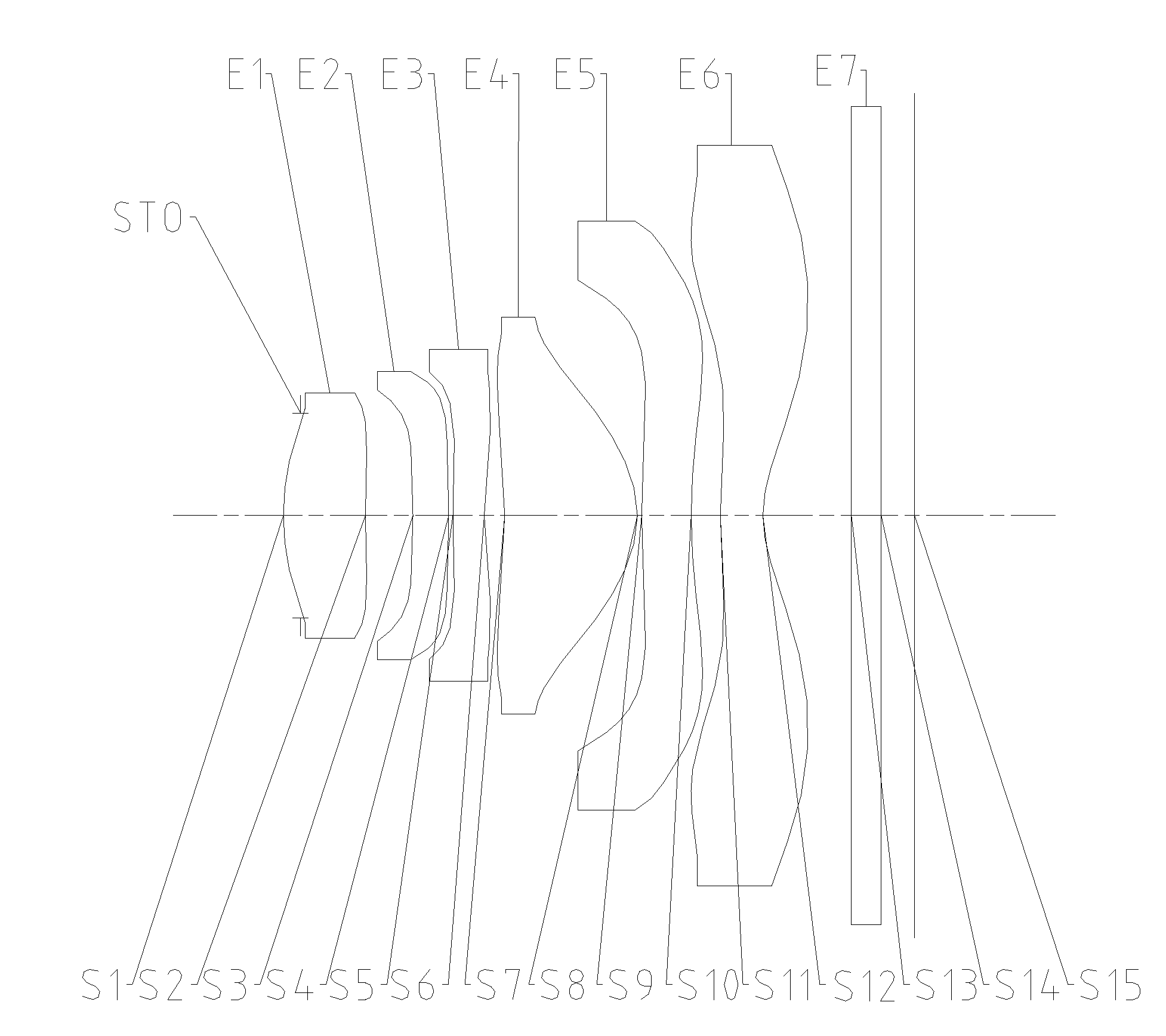
[0028] FIG. 1 is a schematic view of a camera lens according to embodiment 1;
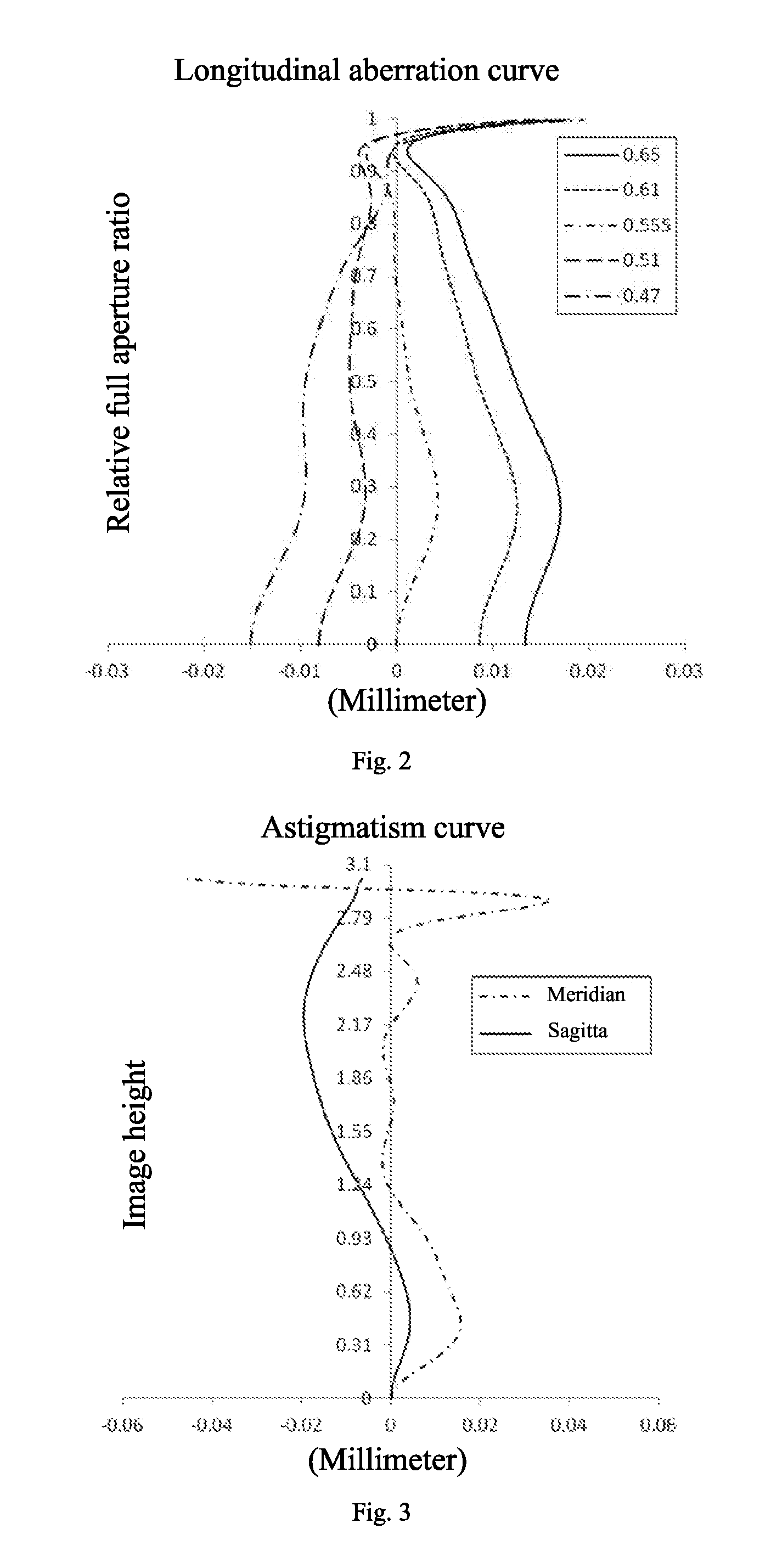
[0029] FIG. 2 is a longitudinal aberration curve (mm) of the camera lens according to embodiment 1;
[0030] FIG. 3 is an astigmatism curve (mm) of the camera lens according to embodiment 1;
[0031] FIG. 4 is a distortion curve (%) of the camera lens according to embodiment 1;
[0032] FIG. 5 is a lateral color curve (.mu.m) of the camera lens according to embodiment 1;
[0033] FIG. 6 is a schematic view of a camera lens according to embodiment 2;
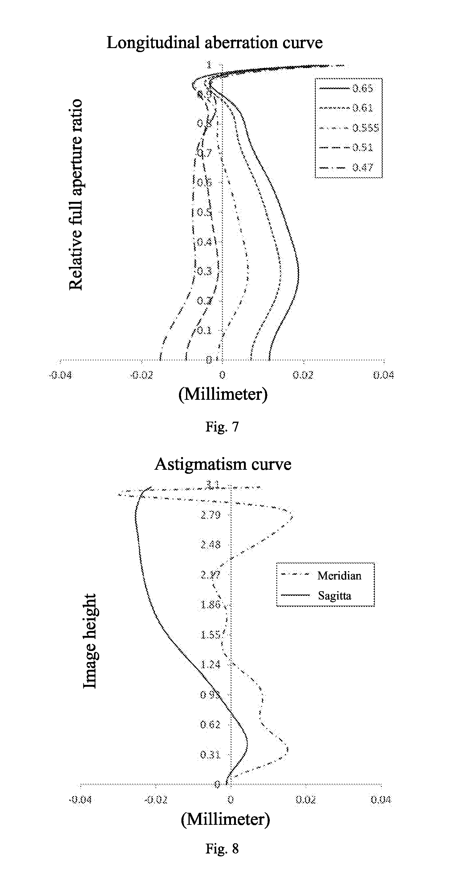
[0034] FIG. 7 is a longitudinal aberration curve (mm) of the camera lens according to embodiment 2;
[0035] FIG. 8 is an astigmatism curve (mm) of the camera lens according to embodiment 2;
[0036] FIG. 9 is a distortion curve (%) of the camera lens according to embodiment 2;
[0037] FIG. 10 is a lateral color curve (.mu.m) of the camera lens according to embodiment 2;
[0038] FIG. 11 is a schematic view of a camera lens according to embodiment 3;
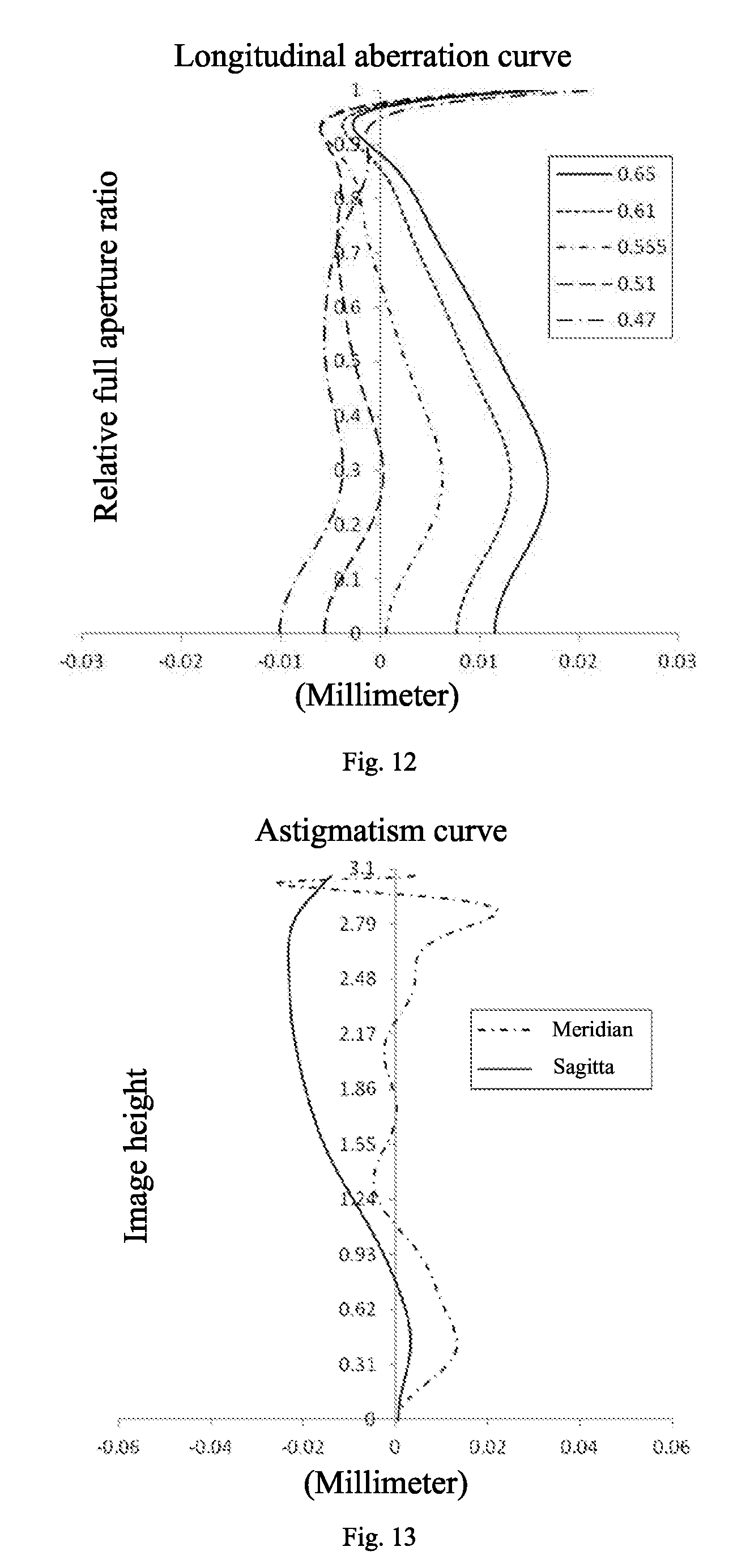
[0039] FIG. 12 is a longitudinal aberration curve (mm) of the camera lens according to embodiment 3;
[0040] FIG. 13 is an astigmatism curve (mm) of the camera lens according to embodiment 3;
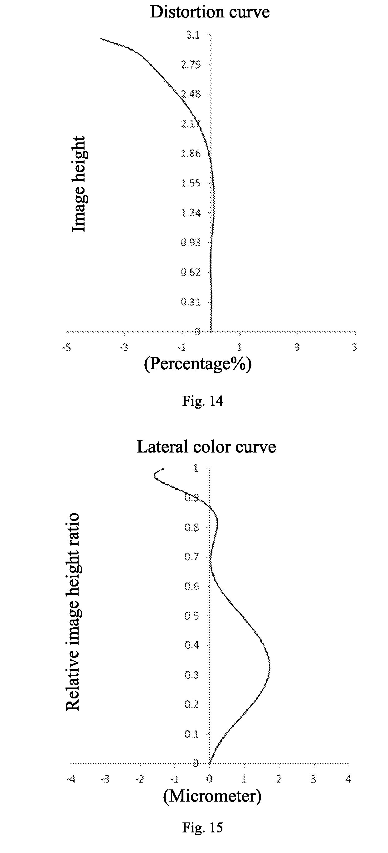
[0041] FIG. 14 is a distortion curve (%) of the camera lens according to embodiment 3;
[0042] FIG. 15 is a lateral color curve (.mu.m) of the camera lens according to embodiment 3;
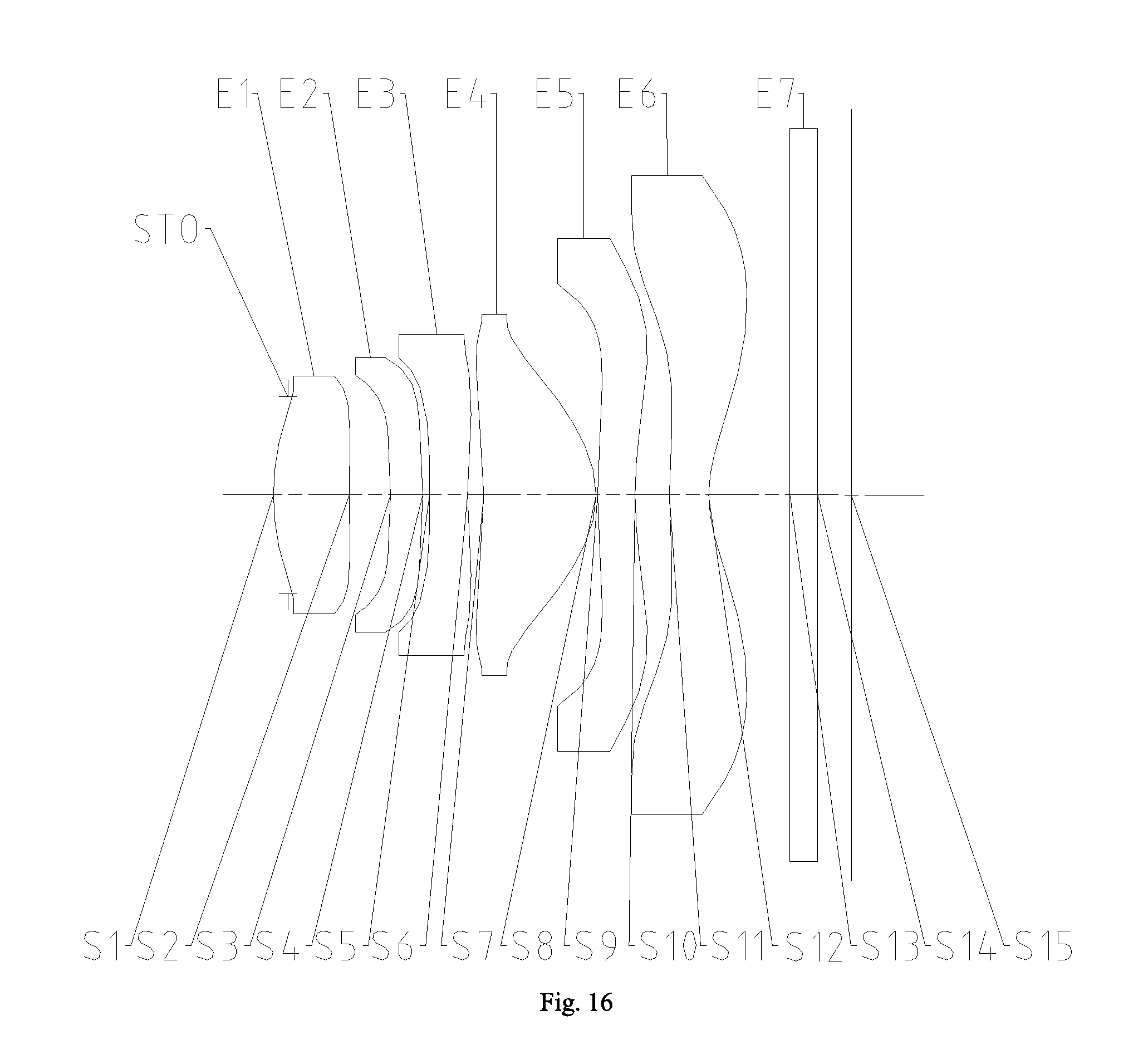
[0043] FIG. 16 is a schematic view of a camera lens according to embodiment 4;
[0044] FIG. 17 is a longitudinal aberration curve (mm) of the camera lens according to embodiment 4;
[0045] FIG. 18 is an astigmatism curve (mm) of the camera lens according to embodiment 4;
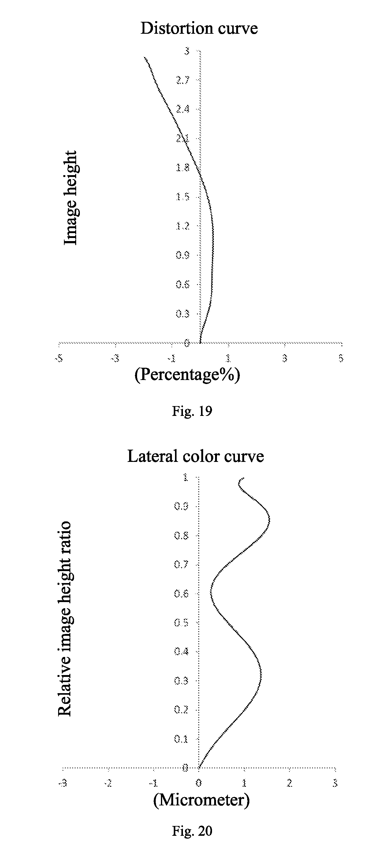
[0046] FIG. 19 is a distortion curve (%) of the camera lens according to embodiment 4;
[0047] FIG. 20 is a lateral color curve (.mu.m) of the camera lens according to embodiment 4;
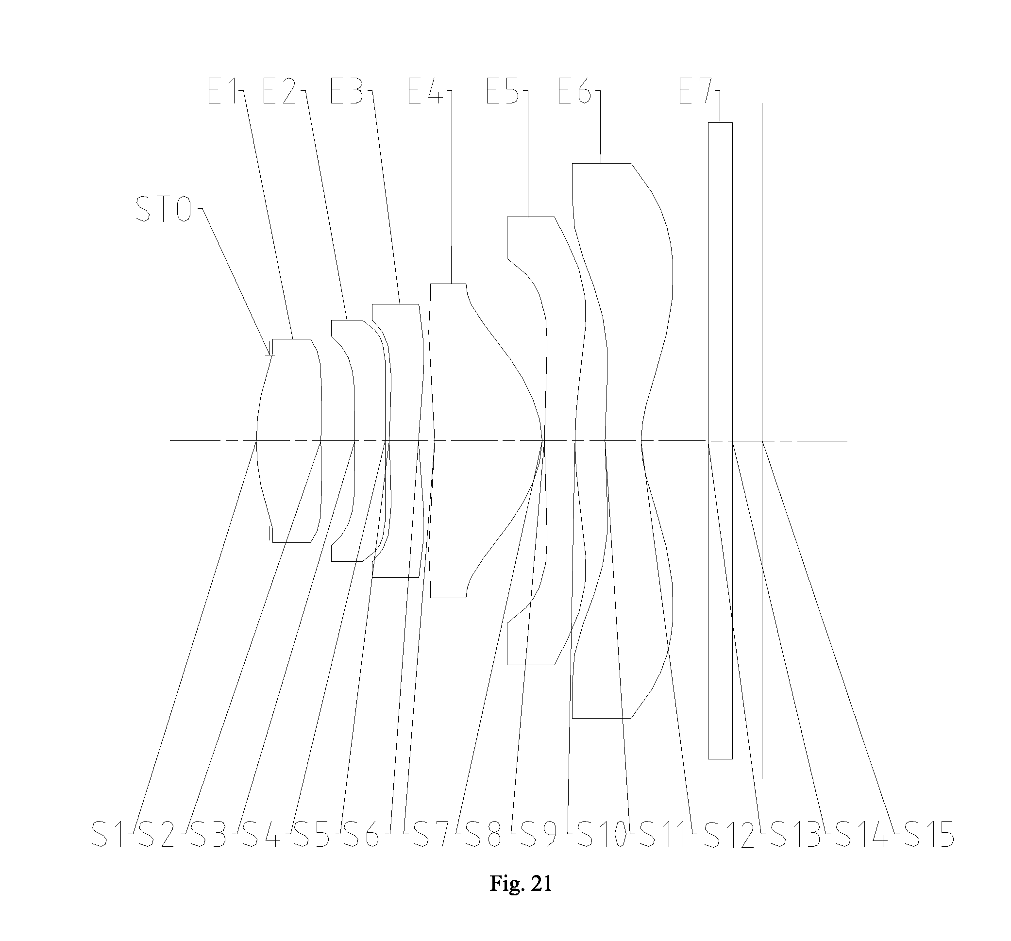
[0048] FIG. 21 is a schematic view of a camera lens according to embodiment 5;
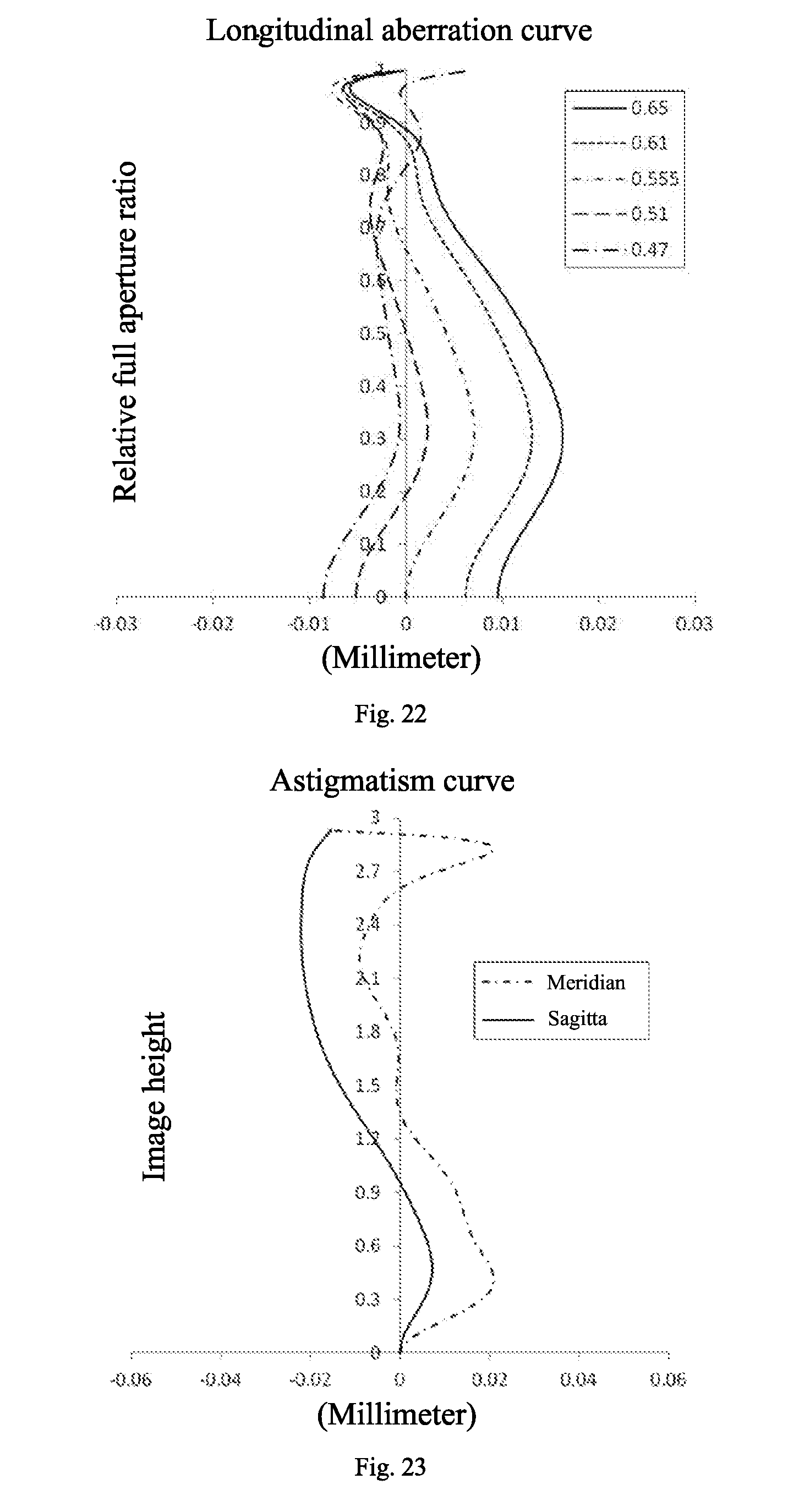
[0049] FIG. 22 is a longitudinal aberration curve (mm) of the camera lens according to embodiment 5;
[0050] FIG. 23 is an astigmatism curve (mm) of the camera lens according to embodiment 5;
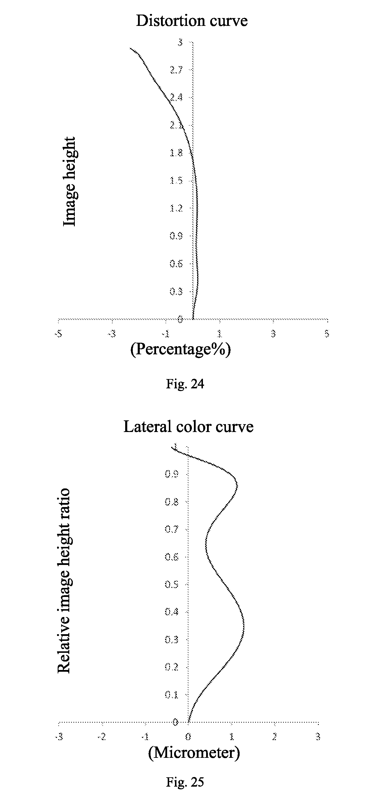
[0051] FIG. 24 is a distortion curve (%) of the camera lens according to embodiment 5;
[0052] FIG. 25 is a lateral color curve (.mu.m) of the camera lens according to embodiment 5;
[0053] FIG. 26 is a schematic view of a camera lens according to embodiment 6;
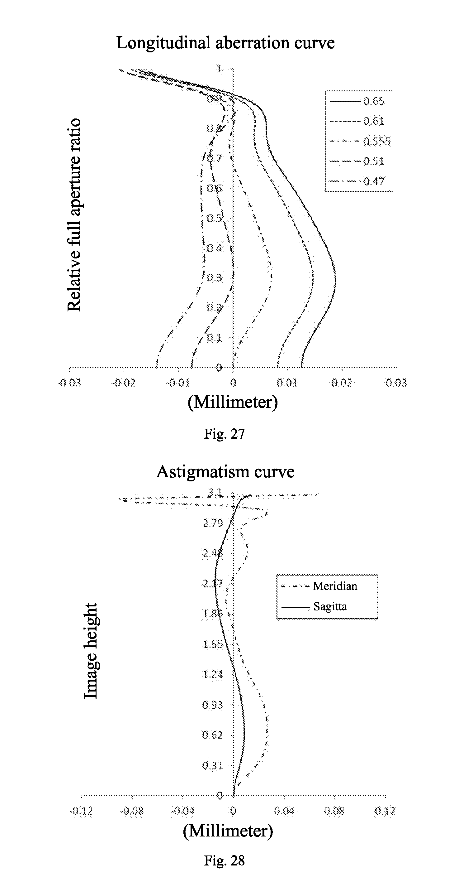
[0054] FIG. 27 is a longitudinal aberration curve (mm) of the camera lens according to embodiment 6;
[0055] FIG. 28 is an astigmatism curve (mm) of the camera lens according to embodiment 6;
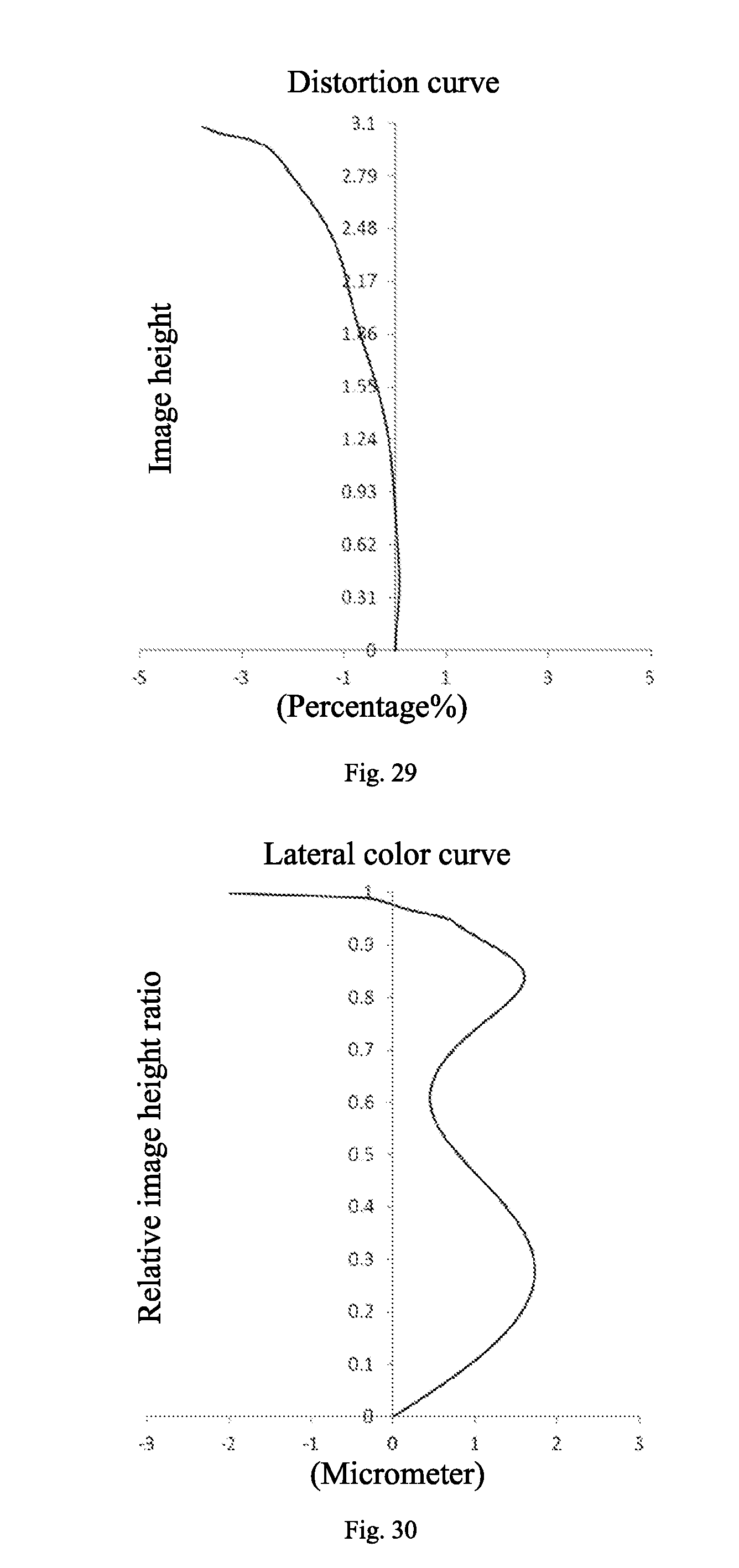
[0056] FIG. 29 is a distortion curve (%) of the camera lens according to embodiment 6;
[0057] FIG. 30 is a lateral color curve (.mu.m) of the camera lens according to embodiment 6;
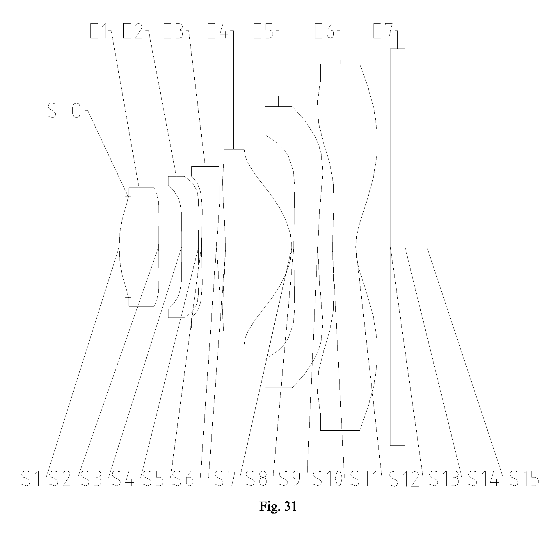
[0058] FIG. 31 is a schematic view of a camera lens according to embodiment 7;
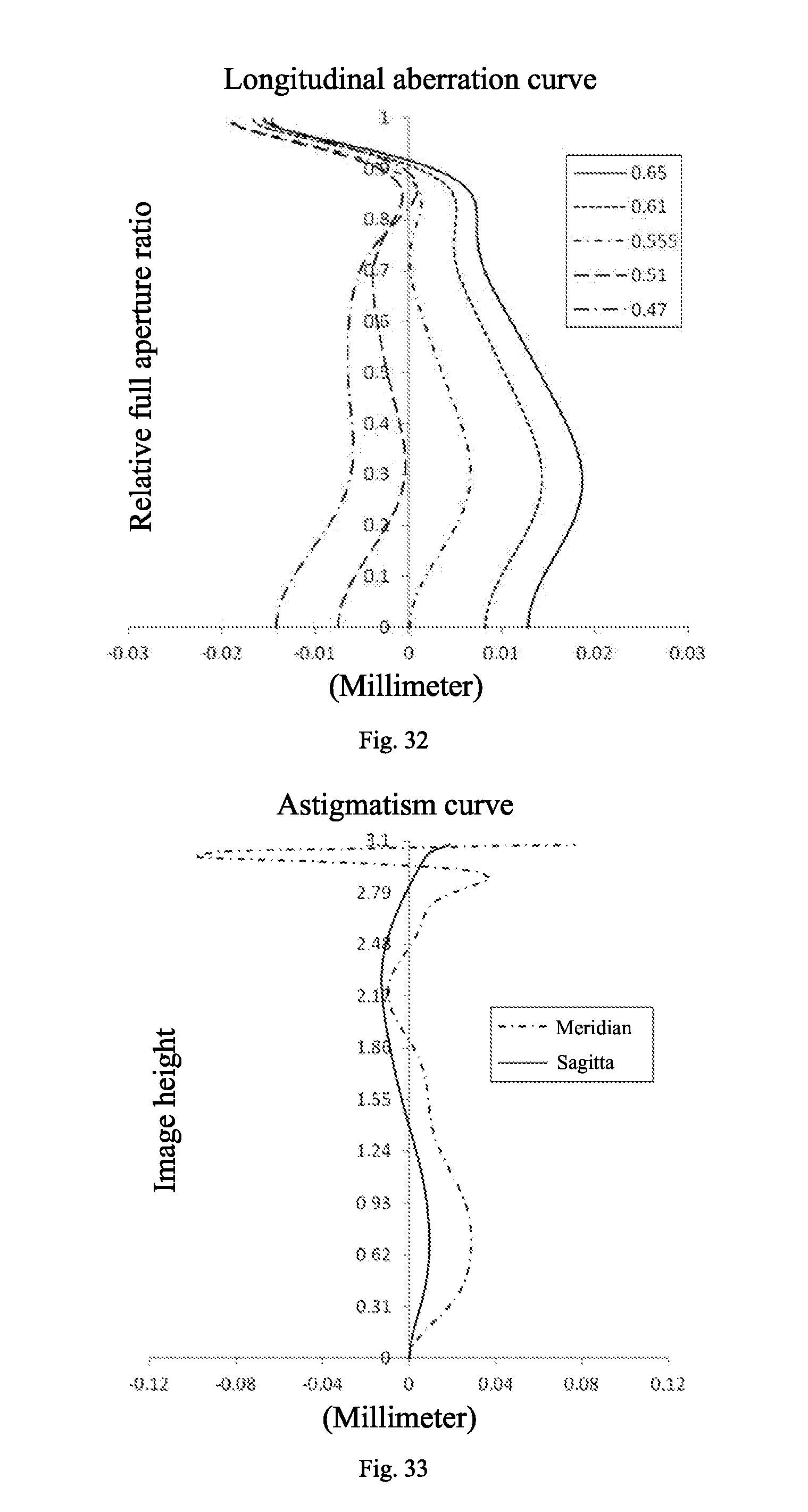
[0059] FIG. 32 is a longitudinal aberration curve (mm) of the camera lens according to embodiment 7;
[0060] FIG. 33 is an astigmatism curve (mm) of the camera lens according to embodiment 7;
[0061] FIG. 34 is a distortion curve (%) of the camera lens according to embodiment 7;
[0062] FIG. 35 is a lateral color curve (.mu.m) of the camera lens according to embodiment 7;
[0063] FIG. 36 is a schematic view of a camera lens according to embodiment 8;
[0064] FIG. 37 is a longitudinal aberration curve (mm) of the camera lens according to embodiment 8;
[0065] FIG. 38 is an astigmatism curve (mm) of the camera lens according to embodiment 8;
[0066] FIG. 39 is a distortion curve (%) of the camera lens according to embodiment 8;
[0067] FIG. 40 is a lateral color curve (.mu.m) of the camera lens according to embodiment 8;
[0068] FIG. 41 is a schematic view of a camera lens according to embodiment 9;
[0069] FIG. 42 is a longitudinal aberration curve (mm) of the camera lens according to embodiment 9;
[0070] FIG. 43 is an astigmatism curve (mm) of the camera lens according to embodiment 9;
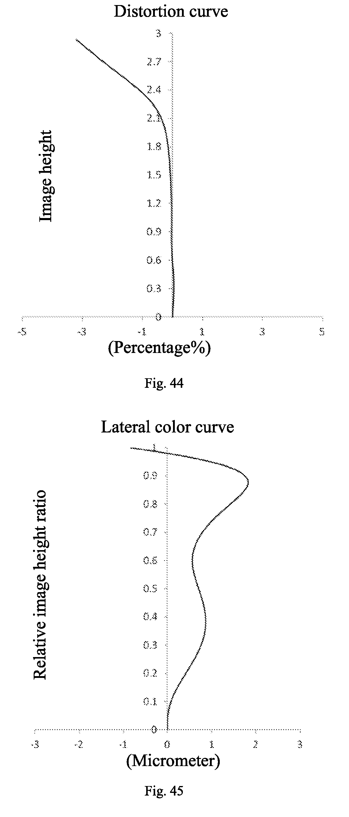
[0071] FIG. 44 is a distortion curve (%) of the camera lens according to embodiment 9;
[0072] FIG. 45 is a lateral color curve (.mu.m) of the camera lens according to embodiment 9;
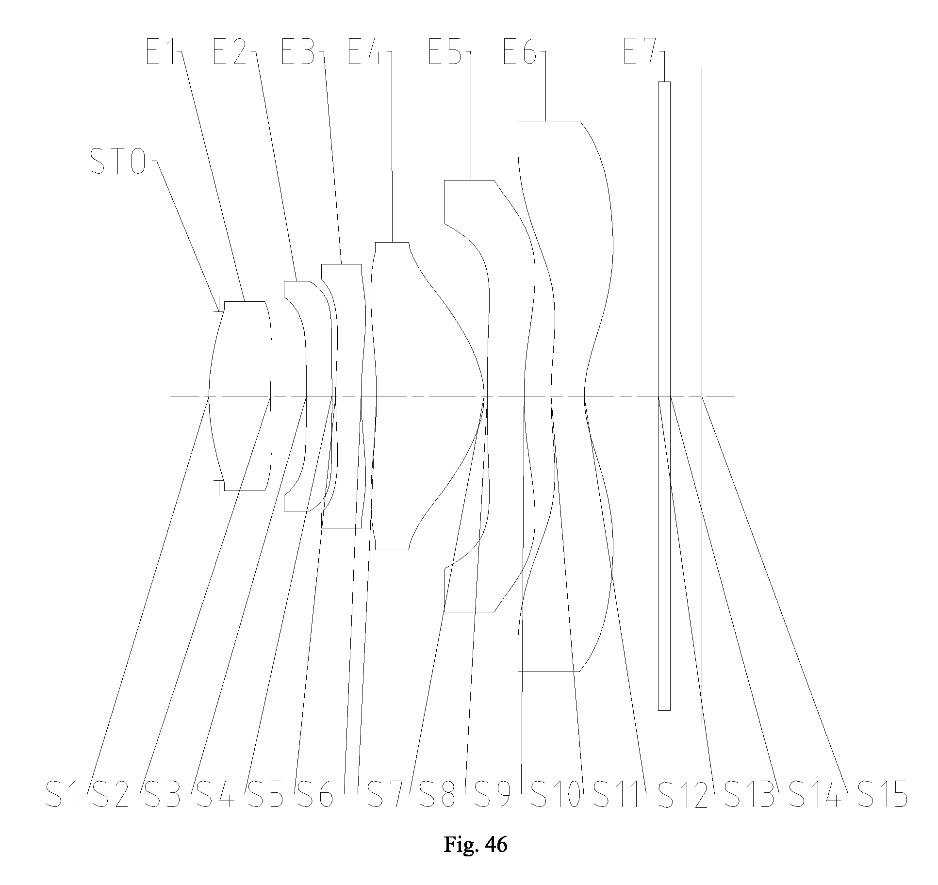
[0073] FIG. 46 is a schematic view of a camera lens according to embodiment 10;
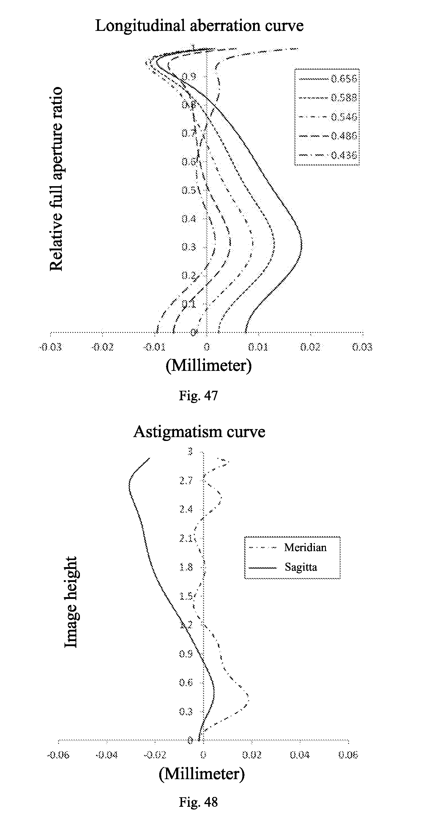
[0074] FIG. 47 is a longitudinal aberration curve (mm) of the camera lens according to embodiment 10;
[0075] FIG. 48 is an astigmatism curve (mm) of the camera lens according to embodiment 10;
[0076] FIG. 49 is a distortion curve (%) of the camera lens according to embodiment 10;
[0077] FIG. 50 is a lateral color curve (.mu.m) of the camera lens according to embodiment 10.
DETAILED DESCRIPTION
[0078] Reference will be made in detail to embodiments of the present disclosure. The same or similar elements and the elements having same or similar functions are denoted by like reference numerals throughout the descriptions. The embodiments described herein with reference to drawings are explanatory, illustrative, and used to generally understand the present disclosure. The embodiments shall not be construed to limit the present disclosure.
[0079] In the description of the present disclosure, it should be understood that, terms such as "first" and "second" are used herein for purposes of description and are not intended to indicate or imply relative importance or significance or to imply the number of indicated technical features. Thus, the feature defined with "first" and "second" may comprise one or more of this feature. In the description of the present invention, the term "a plurality of" means two or more than two, unless specified otherwise.
[0080] In the present invention, unless specified or limited otherwise, the terms "mounted," "connected," "coupled," "fixed" and the like are used broadly, and may be, for example, fixed connections, detachable connections, or integral connections; may also be mechanical or electrical connections; may also be direct connections or indirect connections via intervening structures; may also be inner communications of two elements, which can be understood by those skilled in the art according to specific situations.
[0081] Various embodiments and examples are provided in the following description to implement different structures of the present disclosure. In order to simplify the present disclosure, certain elements and settings will be described. However, these elements and settings are only by way of example and are not intended to limit the present disclosure. In addition, reference numerals may be repeated in different examples in the present disclosure. This repeating is for the purpose of simplification and clarity and does not refer to relations between different embodiments and/or settings. Furthermore, examples of different processes and materials are provided in the present disclosure. However, it would be appreciated by those skilled in the art that other processes and/or materials may be also applied.
[0082] Please refer to FIG. 1, a camera lens according to a preferable embodiment of the present disclosure, in sequence from an object side to an image side, includes:
[0083] a first lens E1 having a positive refractive power, in which an object-side surface S1 of the first lens E1 is a convex surface;
[0084] a second lens E2 having a refractive power;
[0085] a third lens E3 having a negative refractive power, in which an image-side surface S6 of the third lens E3 is concave at a portion near the axis and has at least one point of inflection;
[0086] a fourth lens E4 having a positive refractive power, in which an object-side surface S7 of the fourth lens E4 is a concave at a portion near the axis and has at least one point of inflection, an image-side surface S8 of the fourth lens E4 is a convex surface;
[0087] a fifth lens E5 having a negative refractive power, in which an image-side surface S10 of the fifth lens E5 is concave at a portion near the axis, and at least one of an object-side surface S9 and the image-side surface S10 has at least one point of inflection;
[0088] a sixth lens E6 having a negative refractive power, in which an image-side surface S12 of the sixth lens E6 is concave at a portion near the axis;
[0089] in which, the camera lens satisfies the following relations:
f/f6<-1.0;
f/f4>1.5;
[0090] in which, f denotes an effective focal length of the camera lens, f4 denotes an effective focal length of the fourth lens E4, f6 denotes an effective focal length of the sixth lens E6.
[0091] The camera lens satisfying the above-mentioned configuration facilitates high resolution while improvement of field angle, such that requirements for a large field angle are satisfied, matching with a chip is effectively improved, and a high resolution power and miniaturization of the camera lens are achieved.
[0092] Preferably, the camera lens satisfies the following relation: T23/T12<0.5;
[0093] in which, T12 denotes an axial distance between the first lens E1 and the second lens E2, and T23 denotes a distance between the second lens E2 and the third lens E3 along the axis.
[0094] The camera lens satisfying the above relation facilitates reduction of the distance between the lens, thus shortening a total length of the camera lens, thereby further ensuring the miniaturization of the camera lens.
[0095] Preferably, the camera lens satisfies the following relations:
0.5<f/f1<1.0;
2.0<f1/f4<4.0;
[0096] in which, f denotes the effective focal length of the camera lens, f1 denotes an effective focal length of the first lens E1 and f4 denotes the effective focal length of the fourth lens E4.
[0097] The camera lens satisfying the above relation facilitates distribution of refractive power of a system reasonably, thus effectively correcting an aberration of the system and improving an imaging quality.
[0098] Preferably, the camera lens satisfies the following relation: f/f56<-1.3;
[0099] in which, f denotes the effective focal length of the camera lens, and f56 denotes a combined focal length of the fifth lens E5 and the sixth lens E6.
[0100] The camera lens satisfying the above relation facilitates balance of the refractive power of the system, thus correcting distortion well and reducing an edge aberration of the system.
[0101] Preferably, the camera lens satisfies the following relation: 0.6.ltoreq.Yc32/Yc41.ltoreq.0.85;
[0102] in which, Yc32 denotes a vertical distance between the point of inflection on the image-side surface of the third lens E3 and an optical axis, Yc41 denotes a vertical distance between the point of inflection on the object-side surface of the fourth lens E4 and the optical axis.
[0103] The camera lens satisfying the above relation facilitates reduction of an angle of incidence of an edge chief ray to an image surface, thus ensuring photosensitive efficiency, so that a luminance of the overall image surface may be uniform, and the requirements for high resolution power may be satisfied.
[0104] Preferably, the camera lens satisfies the following relation: ImgH/f.gtoreq.0.9;
[0105] in which, f denotes the effective focal length of the camera lens, ImgH denotes a half of a diagonal line of an effective pixel area in an imaging plane.
[0106] The camera lens satisfying the above relation facilitates improvement of the field angle of the camera lens, thus achieving the large field angle while ensuring the miniaturization of the camera lens.
[0107] Preferably, an object-side surface S11 of the sixth lens E6 in the camera lens is convex at a portion near the axis, and at least one surface of the object-side surface S11 and an image-side surface S12 of the sixth lens E6 has at least one point of inflection.
[0108] Preferably, an image-side surface S2 of the first lens E1 in the camera lens is a concave surface, and an object-side surface S5 of the third lens E3 is convex at a portion near the axis.
[0109] The camera lens satisfying the requirements for shapes of the lens may further improve a relative illumination of the edge of the camera lens, thus improving the resolution power of the camera lens. The distances between the lens are distributed reasonably, so that a structure of the camera lens may be compact relatively, and a volume of the camera lens may be reduced effectively, thus satisfying the requirements of high resolution and miniaturization for a portable electronic product.
[0110] During imaging, after passing through six lens, rays pass through an optical filter E7 having an object-side surface S13 and an image-side surface S14 and then form an image on the imaging plane S15.
[0111] In some embodiments, each of the first lens E1, the second lens E2, the third lens E3, the fourth lens E4, the fifth lens E5 and the sixth lens E6 is an aspheric lens.
[0112] A surface shape of the aspheric surface is decided by the following formula:
x = ch 2 1 + 1 - ( k + 1 ) c 2 h 2 + Aih i ##EQU00001##
[0113] In which, h denotes a height from any point on the aspheric surface to an optical axis, c denotes a curvature of an apex, k denotes a conic constant, Ai denotes an i-th order correction coefficient of the aspheric surface.
Embodiment 1
[0114] Referring to FIG. 1 to FIG. 5, in embodiment 1, the camera lens satisfies the following conditions shown in Table 1 and Table 2:
TABLE-US-00001 TABLE 1 Surface Radius of Refractive index/Abbe Conic Number Surface Type Curvature Thickness number Coefficient OBJ Spherical Surface Infinite 500 -- -- STO Spherical Surface Infinite -0.1210 -- -- S1 Aspheric Surface 1.8947 0.5787 1.544/56.11 0.0727 S2 Aspheric Surface 8.4586 0.3349 -- -42.9715 S3 Aspheric Surface -12.7036 0.2520 1.651/21.52 -99.0000 S4 Aspheric Surface -9.8228 0.0300 -- -0.1103 S5 Aspheric Surface 4.2726 0.2205 1.651/21.52 -99.0000 S6 Aspheric Surface 2.5357 0.1440 -- -22.4375 S7 Aspheric Surface -3.9771 0.9354 1.544/56.11 -31.0304 S8 Aspheric Surface -0.8409 0.0306 -- -3.4069 S9 Aspheric Surface 8.7627 0.3486 1.651/21.52 -99.0000 S10 Aspheric Surface 4.6116 0.2058 -- -59.8711 S11 Aspheric Surface 4.7987 0.3000 1.544/56.11 2.3860 S12 Aspheric Surface 0.9483 0.6237 -- -4.8813 S13 Spherical Surface Infinite 0.2100 1.517/64.17 -- S14 Spherical Surface Infinite 0.2357 -- -- S15 Spherical Surface Infinite -- -- --
TABLE-US-00002 TABLE 2 Surface Number A4 A6 A8 A10 A12 A14 A16 S1 -2.1924E-02 7.3494E-02 -8.0466E-01 3.4889E+00 -8.5186E+00 1.0589E+01 -5.3381E+00 S2 -6.4097E-02 -9.0033E-02 -1.2821E-01 3.1810E-01 -7.7565E-01 9.0507E-01 -4.1130E-01 S3 5.7699E-03 -2.4422E-01 -1.2982E+00 5.6878E+00 -1.2670E+01 1.3413E+01 -5.3147E+00 S4 7.8265E-02 1.3820E-01 -2.0790E+00 6.1617E+00 -8.8631E+00 5.9677E+00 -1.5349E+00 S5 -2.3073E-01 3.9467E-01 -2.1374E+00 6.2433E+00 -8.4017E+00 5.1048E+00 -1.1536E+00 S6 -1.4582E-01 1.1825E-01 -3.7647E-01 7.7509E-01 -7.7340E-01 3.7348E-01 -6.8931E-02 S7 3.5103E-02 8.9982E-02 -2.4789E-01 2.8321E-01 -1.6228E-01 4.6587E-02 -5.4013E-03 S8 -2.1311E-01 2.2510E-01 -2.3050E-01 1.6454E-01 -4.1287E-02 -5.0679E-03 2.6391E-03 S9 2.4192E-02 -8.1756E-02 6.3953E-02 -4.2427E-02 2.0106E-02 -5.7913E-03 6.9386E-04 S10 4.8074E-02 -6.2967E-02 1.7978E-02 1.5515E-03 -2.5054E-03 6.3148E-04 -5.2441E-05 S11 -1.2594E-01 3.2383E-02 -9.1379E-03 4.2601E-03 -1.1489E-03 1.4441E-04 -6.9432E-06 S12 -9.7214E-02 4.2361E-02 -1.4755E-02 3.7370E-03 -6.0836E-04 5.4890E-05 -2.0494E-06
[0115] In addition, f1=4.34 mm; f2=63.78 mm; f3=-10.01 mm; f4=1.77 mm; f5=-15.34 mm; f6=-2.23 mm and f=2.97 mm; HFOV=46.9.degree.; TTL=4.45 mm; Fno=2.0.
Embodiment 2
[0116] Referring to FIG. 6-FIG. 10, in embodiment 2, the camera lens satisfies the following conditions shown in Table 3 and Table 4:
TABLE-US-00003 TABLE 3 Surface Radius of Refractive index/Abbe Conic Number Surface Type Curvature Thickness number Coefficient OBJ Spherical Surface Infinite Infinite -- -- STO Spherical Surface Infinite -0.1210 -- -- S1 Aspheric Surface 1.9192 0.5462 1.544/56.11 -0.1289 S2 Aspheric Surface 8.0800 0.2943 -- -47.1424 S3 Aspheric Surface -14.6666 0.2537 1.651/21.52 -99.0000 S4 Aspheric Surface -11.3886 0.0301 -- 3.2443 S5 Aspheric Surface 3.5686 0.2441 1.651/21.52 -96.2349 S6 Aspheric Surface 2.5356 0.1548 -- -23.1074 S7 Aspheric Surface -3.2688 0.9103 1.544/56.11 -30.2595 S8 Aspheric Surface -0.7420 0.0300 -- -3.8153 S9 Aspheric Surface 9.2058 0.2500 1.651/21.52 -82.3337 S10 Aspheric Surface 2.9277 0.2282 -- -60.6513 S11 Aspheric Surface 4.7760 0.3000 1.544/56.11 2.3205 S12 Aspheric Surface 0.9576 0.6541 -- -5.5000 S13 Spherical Surface Infinite 0.2100 1.517/64.17 -- S14 Spherical Surface Infinite 0.2660 -- -- S15 Spherical Surface Infinite -- -- --
TABLE-US-00004 TABLE 4 Surface Number A4 A6 A8 A10 A12 A14 A16 S1 -2.8204E-02 1.3704E-01 -1.2942E+00 5.4938E+00 -1.3331E+01 1.6678E+01 -8.4992E+00 S2 -7.2753E-02 -2.7539E-02 -8.4746E-01 2.9779E+00 -6.1048E+00 6.4572E+00 -2.7600E+00 S3 3.9957E-02 -2.7259E-01 -1.1582E+00 5.2626E+00 -1.2953E+01 1.5196E+01 -6.6176E+00 S4 7.3554E-02 -1.8313E-01 2.6593E-01 -4.6048E-01 2.3107E-01 -8.4623E-02 3.0077E-02 S5 -1.2659E-01 -5.1310E-01 1.4758E+00 -1.6659E+00 1.0824E+00 -7.4287E-01 3.0619E-01 S6 -1.0501E-01 -7.8477E-02 1.1707E-01 6.3616E-03 -1.3357E-01 1.1270E-01 -2.7714E-02 S7 -2.2959E-02 2.7609E-01 -4.9005E-01 4.0996E-01 -1.6106E-01 2.4865E-02 -5.1344E-04 S8 -3.0160E-01 4.4414E-01 -5.3604E-01 4.2700E-01 -1.6574E-01 2.4597E-02 2.8390E-05 S9 3.6612E-02 -9.5521E-02 5.8403E-02 -4.1004E-02 2.4275E-02 -8.5292E-03 1.1880E-03 S10 6.5963E-02 -9.3555E-02 3.2589E-02 -1.1103E-03 -2.7383E-03 8.2907E-04 -7.7632E-05 S11 -1.3699E-01 3.8799E-02 -1.4815E-02 7.3840E-03 -2.0004E-03 2.5692E-04 -1.2808E-05 S12 -9.7845E-02 4.0753E-02 -1.4011E-02 3.4759E-03 -5.8304E-04 5.5977E-05 -2.2129E-06
[0117] In addition, f1=4.47 mm; f2=75.32 mm; f3=-14.72 mm; f4=1.56 mm; f5=-6.65 mm; f6=-2.26 mm and f=2.97 mm; HFOV=47.0.degree.; TTL=4.37 mm; Fno=2.0.
[0118] Embodiment 3
[0119] Referring to FIG. 11 to FIG. 15, in embodiment 3, the camera lens satisfies the following conditions shown in Table 5 and Table 6:
TABLE-US-00005 TABLE 5 Surface Radius of Refractive index/Abbe Conic Number Surface Type Curvature Thickness number Coefficient OBJ Spherical Surface Infinite Infinite -- -- STO Spherical Surface Infinite -0.1059 -- -- S1 Aspheric Surface 1.9384 0.5668 1.544/56.11 -0.0931 S2 Aspheric Surface 9.6741 0.3045 -- -48.5808 S3 Aspheric Surface -10.6421 0.2601 1.651/21.52 -98.8459 S4 Aspheric Surface -12.3260 0.0300 -- -0.6800 S5 Aspheric Surface 3.4990 0.2500 1.651/21.52 -88.1053 S6 Aspheric Surface 2.4804 0.1471 -- -23.7094 S7 Aspheric Surface -3.7643 0.9208 1.544/56.11 -32.5927 S8 Aspheric Surface -0.7406 0.0300 -- -3.7450 S9 Aspheric Surface 8.4546 0.2426 1.651/21.52 -97.8643 S10 Aspheric Surface 2.6996 0.2539 -- -56.2662 S11 Aspheric Surface 4.8787 0.3000 1.544/56.11 2.3780 S12 Aspheric Surface 0.9596 0.6298 -5.2149 S13 Spherical Surface Infinite 0.2100 1.517/64.17 -- S14 Spherical Surface Infinite 0.2418 -- -- S15 Spherical Surface Infinite -- -- --
TABLE-US-00006 TABLE 6 Surface Number A4 A6 A8 A10 A12 A14 A16 S1 -2.6322E-02 9.0640E-02 -8.8090E-01 3.6195E+00 -8.6997E+00 1.0837E+01 -5.5540E+00 S2 -7.3349E-02 -9.8350E-02 -2.8562E-01 9.8479E-01 -2.1979E+00 2.4906E+00 -1.1376E+00 S3 4.1450E-02 -3.9974E-01 -4.9943E-01 3.3661E+00 -9.4799E+00 1.1759E+01 -5.2728E+00 S4 8.2251E-02 -2.2417E-01 1.5066E-01 4.0038E-01 -1.3876E+00 1.1903E+00 -3.3911E-01 S5 -1.4258E-01 -3.6122E-01 7.0710E-01 3.8834E-01 -1.7934E+00 1.2490E+00 -2.3340E-01 S6 -1.0928E-01 -4.1871E-02 -9.8404E-03 2.3068E-01 -3.2426E-01 1.8713E-01 -3.8238E-02 S7 -1.5545E-02 2.8213E-01 -5.9315E-01 6.3156E-01 -3.6512E-01 1.1175E-01 -1.4487E-02 S8 -2.7962E-01 3.7637E-01 -4.2708E-01 3.3069E-01 -1.2361E-01 1.7093E-02 1.5632E-04 S9 3.8124E-02 -9.2709E-02 5.8150E-02 -3.7387E-02 1.9574E-02 -6.2967E-03 8.2418E-04 S10 5.9863E-02 -8.5837E-02 2.9795E-02 -1.2466E-03 -2.2789E-03 6.7905E-04 -6.1540E-05 S11 -1.3873E-01 3.6890E-02 -1.2297E-02 6.1185E-03 -1.6656E-03 2.1183E-04 -1.0356E-05 S12 -9.7742E-02 4.0250E-02 -1.3079E-02 3.0657E-03 -4.9350E-04 4.6053E-05 -1.7860E-06
[0120] In addition, f1=4.33 mm; f2=-126.42 mm; f3=-14.38 mm; f4=1.52 mm; f5=-6.15 mm; f6=-2.25 mm and f=2.97 mm; HFOV=46.8.degree.; TTL=4.39 mm; Fno=2.0.
Embodiment 4
[0121] Referring to FIG. 16 to FIG. 20, in embodiment 4, the camera lens satisfies the following conditions shown in Table 7 and Table 8:
TABLE-US-00007 TABLE 7 Surface Radius of Refractive index/Abbe Conic Number Surface Type Curvature Thickness number Coefficient OBJ Spherical Surface Infinite Infinite -- -- STO Spherical Surface Infinite -0.1087 -- -- S1 Aspheric Surface 1.8819 0.5728 1.544/56.11 -0.2467 S2 Aspheric Surface 10.9221 0.3119 -- -9.8047 S3 Aspheric Surface -8.0833 0.2437 1.651/21.52 53.0270 S4 Aspheric Surface -5.4662 0.0513 -- -9.3516 S5 Aspheric Surface -700.6079 0.2869 1.651/21.52 94.4069 S6 Aspheric Surface 4.0829 0.1224 -- -13.7811 S7 Aspheric Surface -4.2643 0.8492 1.544/56.11 -25.3911 S8 Aspheric Surface -0.7574 0.0107 -- -3.6098 S9 Aspheric Surface 8.7367 0.2829 1.651/21.52 -30.1887 S10 Aspheric Surface 3.0526 0.2591 -- -52.5216 S11 Aspheric Surface 4.8612 0.2966 1.544/56.11 2.3895 S12 Aspheric Surface 0.9934 0.6149 -- -5.2301 S13 Spherical Surface Infinite 0.2100 1.517/64.17 -- S14 Spherical Surface Infinite 0.2532 -- -- S15 Spherical Surface Infinite -- -- --
TABLE-US-00008 TABLE 8 Surface Number A4 A6 A8 A10 A12 A14 A16 S1 -2.8937E-02 1.0247E-01 -8.5664E-01 3.6016E+00 -8.7314E+00 1.0800E+01 -5.4892E+00 S2 -6.7368E-02 -1.0160E-01 -2.8132E-01 1.0032E+00 -2.2228E+00 2.4825E+00 -1.1582E+00 S3 1.7012E-02 -3.3121E-01 -5.0099E-01 3.3484E+00 -9.5014E+00 1.1753E+01 -5.2552E+00 S4 8.1268E-02 -2.2826E-01 1.5407E-01 4.0877E-01 -1.3879E+00 1.1895E+00 -3.4267E-01 S5 -1.4459E-01 -3.5603E-01 7.0654E-01 3.8557E-01 -1.7955E+00 1.2486E+00 -2.3010E-01 S6 -1.0686E-01 -4.2444E-02 -1.0611E-02 2.2975E-01 -3.2464E-01 1.8695E-01 -3.8273E-02 S7 -1.6255E-02 2.8222E-01 -5.9376E-01 6.3035E-01 -3.6468E-01 1.1201E-01 -1.4398E-02 S8 -2.9290E-01 3.7913E-01 -4.2618E-01 3.3094E-01 -1.2353E-01 1.7202E-02 1.6533E-04 S9 3.7590E-02 -9.2300E-02 5.8255E-02 -3.7365E-02 1.9585E-02 -6.3009E-03 8.2375E-04 S10 5.7904E-02 -8.5891E-02 2.9805E-02 -1.2410E-03 -2.2782E-03 6.7929E-04 -6.1494E-05 S11 -1.3919E-01 3.6872E-02 -1.2298E-02 6.1186E-03 -1.6655E-03 2.1185E-04 -1.0349E-05 S12 -9.6657E-02 4.0263E-02 -1.3080E-02 3.0654E-03 -4.9357E-04 4.6039E-05 -1.7884E-06
[0122] In addition, f1=4.07 mm; f2=24.81 mm; f3=-6.18 mm; f4=1.55 mm; f5=-7.29 mm; f6=-2.35 mm and f=2.92 mm; HFOV=45.5.degree.; TTL=4.37 mm; Fno=2.0.
Embodiment 5
[0123] Referring to FIG. 21 to FIG. 25, in embodiment 5, the camera lens satisfies the following conditions shown in Table 9 and Table 10:
TABLE-US-00009 TABLE 9 Surface Radius of Refractive index/Abbe Conic Number Surface Type Curvature Thickness number Coefficient OBJ Spherical Surface Infinite Infinite -- -- STO Spherical Surface Infinite -0.1179 -- -- S1 Aspheric Surface 1.9260 0.5588 1.544/56.11 -0.1128 S2 Aspheric Surface 9.4685 0.2954 -- -61.5920 S3 Aspheric Surface -22.5902 0.2619 1.651/21.52 -450.2921 S4 Aspheric Surface 864.0394 0.0350 -- -1437.9429 S5 Aspheric Surface 3.1663 0.2533 1.651/21.52 -67.6096 S6 Aspheric Surface 2.3759 0.1410 -- -22.8505 S7 Aspheric Surface -4.5372 0.9312 1.544/56.11 -25.8584 S8 Aspheric Surface -0.7572 0.0183 -- -3.7395 S9 Aspheric Surface 11.6085 0.2649 1.651/21.52 -99.7567 S10 Aspheric Surface 2.9409 0.2600 -- -54.9354 S11 Aspheric Surface 4.8772 0.3123 1.544/56.11 2.3873 S12 Aspheric Surface 0.9889 0.5803 -- -5.4299 S13 Spherical Surface Infinite 0.2100 1.517/64.17 -- S14 Spherical Surface Infinite 0.2595 -- -- S15 Spherical Surface Infinite -- -- --
TABLE-US-00010 TABLE 10 Surface Number A4 A6 A8 A10 A12 A14 A16 S1 -2.7476E-02 9.4885E-02 -8.7823E-01 3.6084E+00 -8.7280E+00 1.0821E+01 -5.4447E+00 S2 -7.3695E-02 -9.2291E-02 -2.8522E-01 9.8152E-01 -2.1948E+00 2.4973E+00 -1.1357E+00 S3 4.7155E-02 -3.9599E-01 -4.9759E-01 3.3682E+00 -9.4731E+00 1.1779E+01 -5.2428E+00 S4 7.4245E-02 -2.2564E-01 1.5446E-01 4.0622E-01 -1.3835E+00 1.1907E+00 -3.4071E-01 S5 -1.3680E-01 -3.5715E-01 7.0754E-01 3.8691E-01 -1.7952E+00 1.2480E+00 -2.3365E-01 S6 -1.0901E-01 -4.2534E-02 -1.0299E-02 2.3050E-01 -3.2431E-01 1.8711E-01 -3.8242E-02 S7 -1.7242E-02 2.8171E-01 -5.9323E-01 6.3155E-01 -3.6513E-01 1.1173E-01 -1.4537E-02 S8 -2.7885E-01 3.7676E-01 -4.2698E-01 3.3071E-01 -1.2361E-01 1.7098E-02 1.5822E-04 S9 3.9966E-02 -9.2648E-02 5.8049E-02 -3.7411E-02 1.9573E-02 -6.2953E-03 8.2487E-04 S10 5.9148E-02 -8.5816E-02 2.9804E-02 -1.2446E-03 -2.2786E-03 6.7914E-04 -6.1530E-05 S11 -1.3899E-01 3.6876E-02 -1.2297E-02 6.1187E-03 -1.6655E-03 2.1185E-04 -1.0351E-05 S12 -9.7332E-02 4.0257E-02 -1.3081E-02 3.0652E-03 -4.9358E-04 4.6039E-05 -1.7884E-06
[0124] In addition, f1=4.32 mm; f2=-33.54 mm; f3=-16.61 mm; f4=1.53 mm; f5=-6.07 mm; f6=-2.34 mm and f=2.95 mm; HFOV=45.4.degree.; TTL=4.38 mm; Fno=2.0.
Embodiment 6
[0125] Referring to FIG. 26 to FIG. 30, in embodiment 6, the camera lens satisfies the following conditions shown in Table 11 and Table 12:
TABLE-US-00011 TABLE 11 Surface Radius of Refractive index/Abbe Conic Number Surface Type Curvature Thickness number Coefficient OBJ Spherical Surface Infinite Infinite -- -- STO Spherical Surface Infinite -0.1133 -- -- S1 Aspheric Surface 1.9542 0.5656 1.544/56.11 0.0260 S2 Aspheric Surface 9.3810 0.3289 -- -111.5663 S3 Aspheric Surface 520.1211 0.2528 1.651/21.52 -1498.2188 S4 Aspheric Surface -31.2093 0.0344 -- 94.9903 S5 Aspheric Surface 3.9123 0.2157 1.651/21.52 -93.0366 S6 Aspheric Surface 2.3979 0.1331 -- -21.5451 S7 Aspheric Surface -4.4045 0.9568 1.544/56.11 -25.0819 S8 Aspheric Surface -0.8476 0.0219 -- -3.4130 S9 Aspheric Surface 12.2487 0.3448 1.651/21.52 -104.4953 S10 Aspheric Surface 4.3760 0.2270 -- -42.7198 S11 Aspheric Surface 4.7848 0.3335 1.544/56.11 2.4005 S12 Aspheric Surface 0.9789 0.5247 -- -5.0752 S13 Spherical Surface Infinite 0.2100 1.517/64.17 -- S14 Spherical Surface Infinite 0.2841 -- -- S15 Spherical Surface Infinite -- -- --
TABLE-US-00012 TABLE 12 Surface Number A4 A6 A8 A10 A12 A14 A16 S1 -2.5634E-02 7.0272E-02 -8.0190E-01 3.4799E+00 -8.5632E+00 1.0549E+01 -5.1575E+00 S2 -6.9777E-02 -8.6072E-02 -1.2356E-01 3.2087E-01 -7.6960E-01 9.1288E-01 -4.1252E-01 S3 8.0706E-03 -2.3417E-01 -1.2844E+00 5.7001E+00 -1.2662E+01 1.3423E+01 -5.3098E+00 S4 6.9145E-02 1.3469E-01 -2.0752E+00 6.1709E+00 -8.8545E+00 5.9708E+00 -1.5374E+00 S5 -2.2759E-01 3.9869E-01 -2.1351E+00 6.2442E+00 -8.4010E+00 5.1084E+00 -1.1490E+00 S6 -1.4592E-01 1.1777E-01 -3.7684E-01 7.7489E-01 -7.7345E-01 3.7360E-01 -6.8540E-02 S7 3.3011E-02 8.9256E-02 -2.4797E-01 2.8322E-01 -1.6224E-01 4.6600E-02 -5.3893E-03 S8 -2.0992E-01 2.2616E-01 -2.3026E-01 1.6459E-01 -4.1296E-02 -5.0904E-03 2.6145E-03 S9 2.6029E-02 -8.2204E-02 6.3494E-02 -4.2531E-02 2.0088E-02 -5.7931E-03 6.9482E-04 S10 4.5555E-02 -6.2901E-02 1.7990E-02 1.5524E-03 -2.5055E-03 6.3142E-04 -5.2458E-05 S11 -1.2646E-01 3.2363E-02 -9.1386E-03 4.2601E-03 -1.1489E-03 1.4442E-04 -6.9415E-06 S12 -9.6787E-02 4.2383E-02 -1.4754E-02 3.7370E-03 -6.0837E-04 5.4886E-05 -2.0510E-06
[0126] In addition, f1=4.40 mm; f2=44.86 mm; f3=-10.0 mm; f4=1.76 mm; f5=-10.56 mm; f6=-2.33 mm and f=2.97 mm; HFOV=47.0.degree.; TTL=4.43 mm; Fno=2.0.
Embodiment 7
[0127] Referring to FIG. 31 to FIG. 35, in embodiment 7, the camera lens satisfies the following conditions shown in Table 13 and Table 14:
TABLE-US-00013 TABLE 13 Surface Radius of Refractive index/Abbe Conic Number Surface Type Curvature Thickness number Coefficient OBJ Spherical Surface Infinite Infinite -- -- STO Spherical Surface Infinite -0.1300 -- -- S1 Aspheric Surface 1.9380 0.5683 1.544/56.11 0.0188 S2 Aspheric Surface 8.9851 0.3333 -- -83.3285 S3 Aspheric Surface 77.1942 0.2450 1.651/21.52 -1384.6512 S4 Aspheric Surface 708.6583 0.0396 -- -1499.8302 S5 Aspheric Surface 3.7153 0.2165 1.651/21.52 -80.1175 S6 Aspheric Surface 2.3942 0.1348 -- -21.6287 S7 Aspheric Surface -4.6801 0.9538 1.544/56.11 -26.9645 S8 Aspheric Surface -0.8580 0.0266 -- -3.4476 S9 Aspheric Surface 13.7513 0.3449 1.651/21.52 -156.4209 S10 Aspheric Surface 5.1735 0.2119 -- -47.0702 S11 Aspheric Surface 4.7867 0.3368 1.544/56.11 2.4058 S12 Aspheric Surface 0.9631 0.5000 -- -4.9943 S13 Spherical Surface Infinite 0.2100 1.517/64.17 -- S14 Spherical Surface Infinite 0.3158 -- -- S15 Spherical Surface Infinite -- -- --
TABLE-US-00014 TABLE 14 Surface Number A4 A6 A8 A10 A12 A14 A16 S1 -2.2959E-02 7.0436E-02 -8.0821E-01 3.4783E+00 -8.5391E+00 1.0581E+01 -5.2153E+00 S2 -6.7575E-02 -8.6602E-02 -1.2165E-01 3.2427E-01 -7.6887E-01 9.1248E-01 -4.1024E-01 S3 9.9674E-03 -2.3507E-01 -1.2911E+00 5.6932E+00 -1.2659E+01 1.3426E+01 -5.2997E+00 S4 6.4966E-02 1.3113E-01 -2.0783E+00 6.1682E+00 -8.8561E+00 5.9699E+00 -1.5377E+00 S5 -2.2686E-01 3.9901E-01 -2.1355E+00 6.2424E+00 -8.4030E+00 5.1057E+00 -1.1503E+00 S6 -1.4501E-01 1.1845E-01 -3.7644E-01 7.7508E-01 -7.7339E-01 3.7355E-01 -6.8724E-02 S7 3.3739E-02 8.9462E-02 -2.4786E-01 2.8310E-01 -1.6223E-01 4.6635E-02 -5.3417E-03 S8 -2.1125E-01 2.2607E-01 -2.3014E-01 1.6466E-01 -4.1255E-02 -5.0768E-03 2.6297E-03 S9 2.5821E-02 -8.2189E-02 6.3678E-02 -4.2493E-02 2.0093E-02 -5.7880E-03 6.9583E-04 S10 4.4877E-02 -6.2966E-02 1.7982E-02 1.5502E-03 -2.5062E-03 6.3127E-04 -5.2481E-05 S11 -1.2655E-01 3.2346E-02 -9.1404E-03 4.2602E-03 -1.1489E-03 1.4442E-04 -6.9403E-06 S12 -9.6849E-02 4.2382E-02 -1.4754E-02 3.7370E-03 -6.0837E-04 5.4887E-05 -2.0500E-06
[0128] In addition, f1=4.40 mm; f2=131.96 mm; f3=-10.97 mm; f4=1.77 mm; f5=-12.84 mm; f6=-2.28 mm and f=2.97 mm; HFOV=47.0.degree.; TTL=4.44 mm; Fno=2.0.
Embodiment 8
[0129] Referring to FIG. 36 to FIG. 40, in embodiment 8, the camera lens satisfies the following conditions shown in Table 15 and Table 16:
TABLE-US-00015 TABLE 15 Surface Radius of Refractive index/Abbe Conic Number Surface Type Curvature Thickness number Coefficient OBJ Spherical Surface Infinite Infinite -- -- STO Spherical Surface Infinite -0.0980 -- -- S1 Aspheric Surface 2.1642 0.5823 1.544/56.11 -0.4085 S2 Aspheric Surface -672.9919 0.2746 -- 94.9616 S3 Aspheric Surface -4.4129 0.2056 1.651/21.52 -11.2869 S4 Aspheric Surface -4.9613 0.0235 -- -23.6475 S5 Aspheric Surface 4.1275 0.2430 1.651/21.52 -129.2766 S6 Aspheric Surface 2.6380 0.1341 -- -26.8760 S7 Aspheric Surface -3.3717 0.9377 1.544/56.11 -28.1483 S8 Aspheric Surface -0.7448 0.0214 -- -3.7604 S9 Aspheric Surface 10.0381 0.2817 1.544/56.11 -42.6926 S10 Aspheric Surface 2.8540 0.2412 -- -59.3769 S11 Aspheric Surface 4.7586 0.3112 1.544/56.11 2.3162 S12 Aspheric Surface 0.9953 0.5584 -- -5.3532 S13 Spherical Surface Infinite 0.2100 1.517/64.17 -- S14 Spherical Surface Infinite 0.3797 -- -- S15 Spherical Surface Infinite -- -- --
TABLE-US-00016 TABLE 16 Surface Number A4 A6 A8 A10 A12 A14 A16 S1 -3.4488E-02 1.3969E-01 -1.2762E+00 5.4801E+00 -1.3441E+01 1.6511E+01 -8.1106E+00 S2 -9.9603E-02 -3.8072E-02 -8.0004E-01 2.9856E+00 -6.1756E+00 6.3809E+00 -2.6127E+00 S3 2.9175E-02 -2.7962E-01 -1.1400E+00 5.2941E+00 -1.2953E+01 1.5152E+01 -6.6439E+00 S4 8.3103E-02 -1.8120E-01 2.6002E-01 -4.6791E-01 2.2841E-01 -8.4722E-02 2.5719E-02 S5 -1.2746E-01 -5.1432E-01 1.4758E+00 -1.6645E+00 1.0824E+00 -7.4498E-01 3.0429E-01 S6 -1.0780E-01 -7.8665E-02 1.1781E-01 6.5033E-03 -1.3374E-01 1.1153E-01 -2.8814E-02 S7 -2.3688E-02 2.7638E-01 -4.8958E-01 4.1010E-01 -1.6119E-01 2.4626E-02 -4.2049E-04 S8 -3.0461E-01 4.4338E-01 -5.3618E-01 4.2713E-01 -1.6547E-01 2.4867E-02 1.9924E-04 S9 4.0951E-02 -9.6896E-02 5.8508E-02 -4.0890E-02 2.4280E-02 -8.5442E-03 1.1730E-03 S10 6.6097E-02 -9.3447E-02 3.2606E-02 -1.1068E-03 -2.7372E-03 8.2937E-04 -7.7545E-05 S11 -1.3660E-01 3.8818E-02 -1.4813E-02 7.3840E-03 -2.0003E-03 2.5694E-04 -1.2817E-05 S12 -9.4694E-02 4.0884E-02 -1.4013E-02 3.4741E-03 -5.8339E-04 5.5917E-05 -2.2229E-06
[0130] In addition, f1=3.95 mm; f2=-71.45 mm; f3=-11.91 mm; f4=1.55 m; f5=-6.17 mm; f6=-2.37 mm and f=2.95 mm; HFOV=47.0.degree.; TTL=4.40 mm; Fno=2.0.
Embodiment 9
[0131] Referring to FIG. 41 to FIG. 45, in embodiment 9, the camera lens satisfies the following conditions shown in Table 17 and Table 18:
TABLE-US-00017 TABLE 17 Surface Radius of Refractive index/Abbe Conic Number Surface Type Curvature Thickness number Coefficient OBJ Spherical Surface Infinite Infinite -- -- STO Spherical Surface Infinite -0.1308 -- -- S1 Aspheric Surface 1.8817 0.6777 1.544/56.11 -0.0807 S2 Aspheric Surface 8.9291 0.2580 -- -258.2261 S3 Aspheric Surface -16.8048 0.1904 1.651/21.52 62.1433 S4 Aspheric Surface -12.8028 0.0419 -- 29.1790 S5 Aspheric Surface 3.5894 0.2379 1.651/21.52 -128.6573 S6 Aspheric Surface 2.2963 0.1214 -- -27.3684 S7 Aspheric Surface -6.9452 0.9414 1.544/56.11 -40.1878 S8 Aspheric Surface -0.8468 0.0300 -- -4.1522 S9 Aspheric Surface -23.5723 0.3079 1.544/56.11 -1445.6162 S10 Aspheric Surface 4.8137 0.4349 -- -147.4755 S11 Aspheric Surface -712.3813 0.2977 1.544/56.11 -1499.7312 S12 Aspheric Surface 1.2337 0.3444 -- -6.3904 S13 Spherical Surface Infinite 0.2100 1.517/64.17 -- S14 Spherical Surface Infinite 0.2343 -- -- S15 Spherical Surface Infinite -- -- --
TABLE-US-00018 TABLE 18 Surface Number A4 A6 A8 A10 A12 A14 A16 S1 -2.7843E-02 1.4704E-01 -1.2732E+00 5.4923E+00 -1.3379E+01 1.6661E+01 -8.3311E+00 S2 -6.8097E-02 -1.4357E-02 -8.6537E-01 2.9697E+00 -6.0976E+00 6.4809E+00 -2.6979E+00 S3 3.4042E-02 -2.8135E-01 -1.1560E+00 5.2445E+00 -1.2953E+01 1.5241E+01 -6.5106E+00 S4 7.4665E-02 -1.7744E-01 2.7825E-01 -4.4471E-01 2.3538E-01 -8.8518E-02 2.2909E-02 S5 -1.1944E-01 -4.9561E-01 1.4854E+00 -1.6662E+00 1.0761E+00 -7.4953E-01 2.9992E-01 S6 -9.0186E-02 -7.9120E-02 1.1418E-01 3.9775E-03 -1.3387E-01 1.1327E-01 -2.6468E-02 S7 -2.2900E-02 2.7756E-01 -4.8951E-01 4.0908E-01 -1.6194E-01 2.4562E-02 -2.3209E-04 S8 -3.0070E-01 4.4353E-01 -5.3770E-01 4.2619E-01 -1.6605E-01 2.4518E-02 -5.4881E-06 S9 5.6280E-02 -1.1614E-01 6.1777E-02 -4.0033E-02 2.4251E-02 -8.6448E-03 1.1090E-03 S10 5.3574E-02 -9.3949E-02 3.2585E-02 -1.0938E-03 -2.7309E-03 8.3185E-04 -7.6703E-05 S11 -1.3242E-01 3.9372E-02 -1.4733E-02 7.3925E-03 -1.9996E-03 2.5695E-04 -1.2806E-05 S12 -9.5064E-02 4.1869E-02 -1.4017E-02 3.4662E-03 -5.8480E-04 5.5720E-05 -2.2440E-06
[0132] In addition, f1=4.22 mm; f2=80.39 mm; f3=-10.47 mm; f4=1.68 mm; f5=-6.06 mm; f6=-2.26 mm and f=2.97 mm; HFOV=45.4.degree.; TTL=4.33 mm; Fno=2.0.
Embodiment 10
[0133] Referring to FIG. 46 to FIG. 50, in embodiment 10, the camera lens satisfies the following conditions shown in Table 19 and Table 20:
TABLE-US-00019 TABLE 19 Surface Radius of Refractive index/Abbe Conic Number Surface Type Curvature Thickness number Coefficient OBJ Spherical Surface Infinite -- -- STO Spherical Surface Infinite -0.0906 -- -- S1 Aspheric Surface 2.0039 0.5567 1.544/56.11 -0.0277 S2 Aspheric Surface 9.9944 0.3243 -- -54.1780 S3 Aspheric Surface -18.8267 0.2300 1.651/21.52 0.5575 S4 Aspheric Surface -34.3722 0.0333 -- -0.1054 S5 Aspheric Surface 3.5758 0.2300 1.651/21.52 -82.8612 S6 Aspheric Surface 2.7721 0.1395 -- -24.1068 S7 Aspheric Surface -3.7793 0.9715 1.544/56.11 -32.0987 S8 Aspheric Surface -0.7351 0.0300 -- -3.6951 S9 Aspheric Surface Infinite 0.3313 1.651/21.52 -90.1512 S10 Aspheric Surface 2.7770 0.2431 -- -63.7914 S11 Aspheric Surface 3.4171 0.3000 1.544/56.11 0.9085 S12 Aspheric Surface 0.9830 0.6692 -- -4.5921 S13 Spherical Surface Infinite 0.1100 1.517/64.17 -- S14 Spherical Surface Infinite 0.2812 -- -- S15 Spherical Surface Infinite -- -- --
TABLE-US-00020 TABLE 20 Surface Number A4 A6 A8 A10 A12 A14 A16 S1 -2.7900E-02 1.0144E-01 -8.7882E-01 3.3270E+00 -7.3738E+00 8.5276E+00 -4.0790E+00 S2 -6.3543E-02 -1.4983E-01 2.0104E-01 -6.8632E-01 1.0935E+00 -9.4601E-01 3.2786E-01 S3 6.0515E-03 -1.6061E-01 -1.2839E+00 4.5528E+00 -9.3361E+00 9.7598E+00 -4.0020E+00 S4 3.0151E-02 7.9459E-02 -7.1979E-01 1.3758E+00 -1.5597E+00 8.0949E-01 -1.5759E-01 S5 -1.4632E-01 -1.1956E-01 1.8678E-01 4.5318E-01 -1.0184E+00 5.1882E-01 -3.7689E-02 S6 -1.3218E-01 8.4359E-02 -2.4450E-01 4.7078E-01 -4.8211E-01 2.5341E-01 -5.1338E-02 S7 -4.2538E-02 3.8004E-01 -6.8466E-01 6.5515E-01 -3.5292E-01 1.0175E-01 -1.2187E-02 S8 -2.1810E-01 2.4639E-01 -2.1124E-01 8.5179E-02 4.0507E-02 -4.2607E-02 9.2765E-03 S9 1.2828E-01 -2.0840E-01 1.7400E-01 -1.3384E-01 7.4679E-02 -2.4995E-02 3.4791E-03 S10 9.5255E-02 -1.3477E-01 5.9465E-02 -1.0576E-02 -1.4224E-03 8.5020E-04 -9.0362E-05 S11 -1.5315E-01 -3.1573E-02 5.3257E-02 -1.9074E-02 3.1522E-03 -2.4301E-04 6.4034E-06 S12 -1.2764E-01 4.5884E-02 -8.9886E-03 7.9496E-04 3.5360E-05 -1.5143E-05 9.9309E-07
[0134] In addition, f1=4.48; f2=-63.63 mm; f3=-21.14 mm; f4=1.50 mm; f5=-4.22 mm; f6=-2.64 mm and f=3.01 mm; HFOV=44.9.degree.; TTL=4.45 mm; Fno=2.0.
[0135] In embodiments 1-10, each conditional expression satisfies conditions shown in the following table.
TABLE-US-00021 Embodiment Formula 1 2 3 4 5 6 7 8 9 10 f/f6 -1.34 -1.32 -1.32 -1.24 -1.26 -1.27 -1.30 -1.24 -1.32 -1.14 f/f4 1.68 1.91 1.94 1.88 1.92 1.69 1.68 1.89 1.77 2.01 T23/T12 0.09 0.10 0.10 0.16 0.12 0.10 0.12 0.09 0.16 0.10 f/f1 0.69 0.67 0.69 0.72 0.68 0.67 0.68 0.75 0.70 0.67 f1/f4 2.45 2.87 2.84 2.62 2.82 2.51 2.49 2.54 2.52 2.98 f/f56 -1.55 -1.85 -1.89 -1.71 -1.84 -1.60 -1.57 -1.81 -1.95 -2.00 Yc32/Yc41 0.74 0.70 0.72 0.66 0.71 0.72 0.75 0.68 0.83 0.78 ImgH/f 1.04 1.04 1.03 1.00 1.00 1.04 1.04 1.05 0.99 0.97
[0136] Reference throughout this specification to "an embodiment," "some embodiments," "one embodiment", "another example," "an example," "a specific example," or "some examples," means that a particular feature, structure, material, or characteristic described in connection with the embodiment or example is included in at least one embodiment or example of the present disclosure. Thus, the appearances of the phrases such as "in some embodiments," "in one embodiment", "in an embodiment", "in another example," "in an example," "in a specific example," or "in some examples," in various places throughout this specification are not necessarily referring to the same embodiment or example of the present disclosure. Furthermore, the particular features, structures, materials, or characteristics may be combined in any suitable manner in one or more embodiments or examples.
[0137] In addition, terms such as "first" and "second" are used herein for purposes of description and are not intended to indicate or imply relative importance or significance. Thus, the feature defined with "first" and "second" may comprise one or more this feature. In the description of the present disclosure, the term "a plurality of" means two or more than two, unless specified otherwise.
[0138] Although explanatory embodiments have been shown and described, it would be appreciated by those skilled in the art that the above embodiments cannot be construed to limit the present disclosure, and changes, alternatives, and modifications can be made in the embodiments without departing from spirit, principles and scope of the present disclosure.
* * * * *
D00000
D00001
D00002
D00003
D00004
D00005
D00006
D00007
D00008
D00009
D00010
D00011
D00012
D00013
D00014
D00015
D00016

D00017
D00018
D00019
D00020
D00021

D00022

D00023

D00024

D00025

D00026

D00027
D00028
D00029
D00030


P00001

XML
uspto.report is an independent third-party trademark research tool that is not affiliated, endorsed, or sponsored by the United States Patent and Trademark Office (USPTO) or any other governmental organization. The information provided by uspto.report is based on publicly available data at the time of writing and is intended for informational purposes only.
While we strive to provide accurate and up-to-date information, we do not guarantee the accuracy, completeness, reliability, or suitability of the information displayed on this site. The use of this site is at your own risk. Any reliance you place on such information is therefore strictly at your own risk.
All official trademark data, including owner information, should be verified by visiting the official USPTO website at www.uspto.gov. This site is not intended to replace professional legal advice and should not be used as a substitute for consulting with a legal professional who is knowledgeable about trademark law.