High Strength Thick-walled Elecric-resistance-welded Steel Pipe For Deep-well Conductor Casing, Method For Manufacturing The Same, And High Strength Thick-walled Conductor Casing For Deep Wells
GOTO; Sota ; et al.
U.S. patent application number 15/539421 was filed with the patent office on 2017-12-28 for high strength thick-walled elecric-resistance-welded steel pipe for deep-well conductor casing, method for manufacturing the same, and high strength thick-walled conductor casing for deep wells. This patent application is currently assigned to JFE Steel Corporation. The applicant listed for this patent is JFE STEEL CORPORATION. Invention is credited to Sota GOTO, Takatoshi OKABE, Yukihiko OKAZAKI.
| Application Number | 20170369962 15/539421 |
| Document ID | / |
| Family ID | 56149691 |
| Filed Date | 2017-12-28 |


| United States Patent Application | 20170369962 |
| Kind Code | A1 |
| GOTO; Sota ; et al. | December 28, 2017 |
HIGH STRENGTH THICK-WALLED ELECRIC-RESISTANCE-WELDED STEEL PIPE FOR DEEP-WELL CONDUCTOR CASING, METHOD FOR MANUFACTURING THE SAME, AND HIGH STRENGTH THICK-WALLED CONDUCTOR CASING FOR DEEP WELLS
Abstract
A high-strength high-toughness electric-resistance-welded steel pipe having high resistance to post-weld heat treatment is provided. The steel pipe having a composition including C: 0.01% to 0.12%, Si: 0.05% to 0.50%, Mn: 1.0% to 2.2%, P: 0.03% or less, S: 0.005% or less, Al: 0.001% to 0.10%, N: 0.006% or less, Nb: 0.010% to 0.100%, and Ti: 0.001% to 0.050%. The steel pipe having a structure composed of 90% or more by volume of a bainitic ferrite phase and 10% or less (including 0%) by volume of a second phase. The bainitic ferrite phase having an average grain size of 10 .mu.m or less, and the structure containing fine Nb precipitates having a particle size of less than 20 nm dispersed in a base material portion. The steel pipe having high strength and toughness that is maintained through post-weld heat treatment, including heating to a temperature of 600.degree. C. or more.
| Inventors: | GOTO; Sota; (Kawasaki, JP) ; OKABE; Takatoshi; (Handa, JP) ; OKAZAKI; Yukihiko; (Handa, JP) | ||||||||||
| Applicant: |
|
||||||||||
|---|---|---|---|---|---|---|---|---|---|---|---|
| Assignee: | JFE Steel Corporation Tokyo JP |
||||||||||
| Family ID: | 56149691 | ||||||||||
| Appl. No.: | 15/539421 | ||||||||||
| Filed: | December 15, 2015 | ||||||||||
| PCT Filed: | December 15, 2015 | ||||||||||
| PCT NO: | PCT/JP2015/006233 | ||||||||||
| 371 Date: | June 23, 2017 |
| Current U.S. Class: | 1/1 |
| Current CPC Class: | C21D 6/001 20130101; C21D 2211/002 20130101; B21C 37/08 20130101; C21D 6/008 20130101; C21D 9/50 20130101; C22C 38/58 20130101; C22C 38/06 20130101; C22C 38/14 20130101; C21D 9/08 20130101; C21D 8/0226 20130101; C21D 8/105 20130101; C22C 38/02 20130101; B21B 19/10 20130101; C21D 2211/005 20130101; C21D 6/005 20130101; C21D 8/0263 20130101; C22C 38/00 20130101; C21D 8/02 20130101; C22C 38/04 20130101; C21D 8/0205 20130101 |
| International Class: | C21D 9/08 20060101 C21D009/08; C22C 38/06 20060101 C22C038/06; C22C 38/04 20060101 C22C038/04; C22C 38/14 20060101 C22C038/14; C21D 8/02 20060101 C21D008/02; B21B 19/10 20060101 B21B019/10; C21D 9/50 20060101 C21D009/50; C21D 8/10 20060101 C21D008/10; B21C 37/08 20060101 B21C037/08; C22C 38/02 20060101 C22C038/02 |
Foreign Application Data
| Date | Code | Application Number |
|---|---|---|
| Dec 25, 2014 | JP | 2014-262105 |
Claims
1. A high-strength thick-walled electric-resistance-welded steel pipe for a deep-well conductor casing, the steel pipe having a composition comprising: C: 0.01% to 0.12%, by mass %; Si: 0.05% to 0.50%, by mass %; Mn: 1.0% to 2.2%, by mass %; P: 0.03% or less, by mass %; S: 0.005% or less, by mass %; Al: 0.001% to 0.10%, by mass %; N: 0.006% or less, by mass % Nb: 0.010% to 0.100%, by mass %; Ti: 0.001% to 0.050%, by mass %; and Fe and incidental impurities, wherein: the steel pipe has a structure composed of 90% or more by volume of a bainitic ferrite phase as a main phase and 10% or less (including 0%) by volume of a second phase, the bainitic ferrite phase having an average grain size of 10 .mu.m or less, and the structure containing fine Nb precipitates having a particle size of less than 20 nm dispersed in a base material portion, a ratio of fine Nb precipitates to a total amount of Nb being 75% or less on a Nb equivalent basis, and a circularity of an end portion of the steel pipe defined by formula (1) being 0.6% or less, circularity (%)={(maximum outer diameter mm.phi. of steel pipe)-(minimum outer diameter mm.phi. of steel pipe)}/(nominal outer diameter mm.phi.).times.100 formula (1).
2. The high-strength thick-walled electric-resistance-welded steel pipe for a deep-well conductor casing according to claim 1, wherein the composition further comprises at least one of: V: 0.1% or less, by mass %; Mo: 0.5% or less, by mass %; Cr: 0.5% or less, by mass %; Cu: 0.5% or less, by mass %; Ni: 1.0% or less, by mass %; and B: 0.0030% or less, by mass %.
3. The high-strength thick-walled electric-resistance-welded steel pipe for a deep-well conductor casing according to claim 1, wherein the composition further comprises at least one of: Ca: 0.0050% or less, by mass %; and REM: 0.0050% or less, by mass %.
4. A method for manufacturing a high-strength thick-walled electric-resistance-welded steel pipe for a deep-well conductor casing, the method comprising: continuously rolling a hot-rolled steel plate with a roll forming machine to form an open pipe having a generally circular cross section; butting edges of the open pipe; electric-resistance-welding a portion where the edges are being butted while pressing the butted edges to contact each other by squeeze rolls to form an electric-resistance-welded steel pipe; subjecting the electric-resistance-welded portion of the electric-resistance-welded steel pipe to in-line heat treatment; and reducing a diameter of the electric-resistance-welded steel pipe by rolling, wherein: the hot-rolled steel plate is manufactured by: heating to soak a steel at a heating temperature in the range of 1150.degree. C. to 1250.degree. C. for 60 minutes or more, hot-rolling the steel with a finishing delivery temperature of 750.degree. C. or more, after completion of the hot rolling, subjecting the hot-rolled steel plate to accerelated cooling such that an average cooling rate in a temperature range of 750.degree. C. to 650.degree. C. at the center of plate thickness ranges from 8.degree. C./s to 70.degree. C./s, and coiling the hot-rolled steel plate at a coiling temperature in the range of 580.degree. C. to 400.degree. C., the hot-rolled steel plate has a composition comprising: C: 0.01% to 0.12%, by mass %, Si: 0.05% to 0.50%, by mass %, Mn: 1.0% to 2.2%, by mass %, P: 0.03% or less, by mass %, S: 0.005% or less, by mass %, Al: 0.001% to 0.10%, by mass %, N: 0.006% or less, by mass %, Nb: 0.010% to 0.100%, by mass %, Ti: 0.001% to 0.050%, by mass %, and Fe and incidental impurities.
5. The method for manufacturing a high-strength thick-walled electric-resistance-welded steel pipe for a deep-well conductor casing according to claim 4, wherein the roll forming machine includes a cage roll group composed of a plurality of rolls and a fin pass forming roll group composed of a plurality of rolls.
6. The method for manufacturing a high-strength thick-walled electric-resistance-welded steel pipe for a deep-well conductor casing according to claim 5, wherein two or more portions of an inner wall of the hot-rolled steel plate are pressed with an inner roll disposed downstream of the cage roll group during a forming process.
7. The method for manufacturing a high-strength thick-walled electric-resistance-welded steel pipe for a deep-well conductor casing according to claim 4, wherein the in-line heat treatment of the electric-resistance-welded portion includes heating the electric-resistance-welded portion to a heating temperature in the range of 830.degree. C. to 1150.degree. C. and cooling the electric-resistance-welded portion to a cooling stop temperature of 550.degree. C. or less at the center of the late thickness such that an average cooling rate in a temperature range of 800.degree. C. to 550.degree. C. at the center of the plate thickness ranges from 10.degree. C./s to 70.degree. C./s.
8. The method for manufacturing a high-strength thick-walled electric-resistance-welded steel pipe for a deep-well conductor casing according to claim 4, wherein a reduction ratio in the reducing rolling is in a range of 0.2% to 3.3%.
9. The method for manufacturing a high-strength thick-walled electric-resistance-welded steel pipe for a deep-well conductor casing according to claim 4, wherein the composition further comprises at least one of: V: 0.1% or less, by mass %, Mo: 0.5% or less, by mass %, Cr: 0.5% or less, by mass %, Cu: 0.5% or less, by mass %, Ni: 1.0% or less, by mass %, and B: 0.0030% or less, by mass %.
10. The method for manufacturing a high-strength thick-walled electric-resistance-welded steel pipe for a deep-well conductor casing according to claim 4, wherein the composition further comprises at least one of: Ca: 0.0050% or less, by mass %, and REM: 0.0050% or less, by mass %.
11. A high-strength thick-walled conductor casing for deep wells, the conduct casing comprising a screw member disposed on each end of the high-strength thick-walled electric-resistance-welded steel pipe for a deep-well conductor casing according to claim 1.
12. The high-strength thick-walled electric-resistance-welded steel pipe for a deep-well conductor casing according to claim 2, wherein the composition further comprises at least one of: Ca: 0.0050% or less, by mass %; and REM: 0.0050% or less, by mass %.
13. The method for manufacturing a high-strength thick-walled electric-resistance-welded steel pipe for a deep-well conductor casing according to claim 7, wherein a reduction ratio in the reducting rolling is in a range of 0.2% to 3.3%.
14. The method for manufacturing a high-strength thick-walled electric-resistance-welded steel pipe for a deep-well conductor casing according to claim 7, wherein the composition further comprises at least one of: V: 0.1% or less, by mass %, Mo: 0.5% or less, by mass %, Cr: 0.5% or less, by mass %, Cu: 0.5% or less, by mass %, Ni: 1.0% or less, by mass %, and B: 0.0030% or less, by mass %.
15. The method for manufacturing a high-strength thick-walled electric-resistance-welded steel pipe for a deep-well conductor casing according to claim 8, wherein the composition further comprises at least one of: V: 0.1% or less, by mass %, Mo: 0.5% or less, by mass %, Cr: 0.5% or less, by mass %, Cu: 0.5% or less, by mass %, Ni: 1.0% or less, by mass %, and B: 0.0030% or less, by mass %.
16. The method for manufacturing a high-strength thick-walled electric-resistance-welded steel pipe for a deep-well conductor casing according to claim 7, wherein the composition further comprises at least one of: Ca: 0.0050% or less, by mass %, and REM: 0.0050% or less, by mass %.
17. The method for manufacturing a high-strength thick-walled electric-resistance-welded steel pipe for a deep-well conductor casing according to claim 8, wherein the composition further comprises at least one of: Ca: 0.0050% or less, by mass %, and REM: 0.0050% or less, by mass %.
18. The method for manufacturing a high-strength thick-walled electric-resistance-welded steel pipe for a deep-well conductor casing according to claim 9, wherein the composition further comprises at least one of: Ca: 0.0050% or less, by mass %, and REM: 0.0050% or less, by mass %.
19. A high-strength thick-walled conductor casing for deep wells, the conduct casing comprising a screw member disposed on each end of the high-strength thick-walled electric-resistance-welded steel pipe for a deep-well conductor casing according to claim 2.
20. A high-strength thick-walled conductor casing for deep wells, the conduct casing comprising a screw member disposed on each end of the high-strength thick-walled electric-resistance-welded steel pipe for a deep-well conductor casing according to claim 3.
Description
TECHNICAL FIELD
[0001] The present disclosure relates to an electric-resistance-welded steel pipe suitable for a conductor casing used as a retaining wall in oil or gas well drilling and more particularly to a high-strength thick-walled electric-resistance-welded steel pipe suitable for a conductor casing for wells in deep-water oil or gas field development at a depth of 3,000 m or more (hereinafter also referred to as deep wells) and to a method for manufacturing the high-strength thick-walled electric-resistance-welded steel pipe.
BACKGROUND ART
[0002] Conductor casings are used as retaining walls in wells at an early stage of oil or gas well drilling and protect oil well pipes from external pressure. Conductor casings are conventionally manufactured by joining a UOE steel pipe to a connector (threaded forged member).
[0003] When placed into wells, conductor casings are repeatedly subjected to bending deformation. When placed into deep wells, conductor casings are also subjected to stress loading due to their own weights. Thus, deep-well conductor casings are particularly required
[0004] (1) not to be broken by repeated bending deformation during placement, and
[0005] (2) to have strength to bear their own weights.
[0006] In order to prevent conductor casings from being broken by bending deformation, it is particularly necessary to reduce stress concentration, for example, caused by linear misalignment in a joint. Linear misalignment may be reduced by improving the circularity of a steel pipe to be used.
[0007] In general, conductor casings are sometimes subjected to post-weld heat treatment at a temperature of 600.degree. C. or more in order to relieve the residual stress of a joint between a steel pipe and a forged member or to prevent hydrogen cracking. Thus, there is a demand for a steel pipe that suffers a smaller decrease in strength due to post-weld heat treatment, can maintain desired strength even after post-weld heat treatment, and has high resistance to post-weld heat treatment.
[0008] For example, Patent Literature 1 describes a high-strength riser steel pipe having good high-temperature stress relief (SR) characteristics to meet the demand. In the technique described in Patent Literature 1, a riser steel pipe having good high-temperature SR characteristics has a steel composition containing C: 0.02% to 0.18%, Si: 0.05% to 0.50%, Mn: 1.00% to 2.00%, Cr: 0.30% to 1.00%, Ti: 0.005% to 0.030%, Nb: 0.060% or less, and Al: 0.10% or less by weight. In the technique described in Patent Literature 1, in addition to these components, a riser steel pipe may further contain one or two or more of Cu: 0.50% or less, Ni: 0.50% or less, Mo: 0.50% or less, and V: 0.10% or less, and further Ca: 0.0005% to 0.0050% and/or B: 0.0020% or less by weight. In the technique described in Patent Literature 1, inclusion of a predetermined amount of Cr retards softening of the base material ferrite and increases resistance to softening, which can suppress the decrease in toughness and strength caused by post-weld heat treatment (SR treatment) and improve high-temperature SR characteristics.
[0009] Patent Literature 2 describes, as a technique for improving the circularity of a steel pipe, a method for expanding a UOE steel pipe by using a pipe expander in which each dice of all mounted on the pipe expander has a grooved outer surface, and changing the dies mounted on the pipe expander for each steel pipe to be expanded, each of the dies facing a piece of excess weld metal inside a steel pipe weld portion. Patent Literature 2 states that the technique can uniformize the wear loss of the dies mounted on the pipe expander and improve the circularity of a steel pipe.
CITATION LIST
Patent Literature
[0010] PTL 1: Japanese Patent No. 3558198
[0011] PTL 2: Japanese Unexamined Patent Application Publication No. 2006-289439
SUMMARY
Technical Problem
[0012] In order to prevent a conductor casing from being broken by repeated bending deformation during placement, it is important to reduce stress concentration. Thus, a steel pipe to which a connector is to be joined should have a certain degree of circularity. However, Patent Literature 1 does not describe a measure to improve circularity, for example, by reducing linear misalignment. The technique described in Patent Literature 1 includes no measure to improve circularity, and a steel pipe will have insufficient circularity at its end portion, particularly when used as a deep-well conductor casing. When a steel pipe manufactured by the technique described in Patent Literature 1 is used as a deep-well conductor casing, an additional step is necessary to improve the circularity of an end portion of the steel pipe by cutting or straightening. Thus, there is a problem in the technique described in Literature 1 that the productivity of manufacturing conductor casings is decreased.
[0013] The technique described in Patent Literature 2 also cannot ensure sufficient circularity particularly for deep-well conductor casings, which is a problem.
[0014] The present disclosure solves such problems of the related art and aims to provide a high-strength high-toughness thick-walled electric-resistance-welded steel pipe having high resistance to post-weld heat treatment suitable for a deep-well conductor casing and a method for manufacturing the steel pipe. The present disclosure also aims to provide a conductor casing including the electric-resistance-welded steel pipe as a component thereof.
[0015] The term "high-strength thick-walled electric-resistance-welded steel pipe", as used herein, refers to a thick-walled electric-resistance-welded steel pipe having a thickness of 15 mm or more in which both a base material portion and an electric-resistance-welded portion have high strength of at least the API X80 grade. The base material portion has a yield strength YS of 555 MPa or more and a tensile strength TS of 625 MPa or more, and the electric-resistance-welded portion has a tensile strength TS of 625 MPa or more. The term "high toughness", as used herein, means that the absorbed energy vE.sub.-40 in a Charpy impact test at a test temperature of -40.degree. C. is 27 J or more. For placement in deep water, the thickness is preferably 20 mm or more.
[0016] The phrase "high resistance to post-weld heat treatment", as used herein, means that the base material maintains the strength of at least the API X80 grade even after post-weld heat treatment performed at 600.degree. C. or more.
Solution to Problem
[0017] In order to achieve the objects, the present inventors have intensively studied the characteristics of a steel pipe suitable for a deep-well conductor casing. As a result, the present inventors have found that in order to prevent a conductor casing from being broken by bending deformation during placement, it is necessary to use a steel pipe having a circularity of 0.6% or less. The present inventors have found that if a steel pipe to be used has a circularity of 0.6% or less, linear misalignment between a threaded member and a joint (an end portion of the steel pipe) can be reduced to prevent the steel pipe from being broken by repeated bending deformation, without a particular additional process, such as cutting or straightening.
[0018] The present inventors have considered that such a steel pipe is preferably an electric-resistance-welded steel pipe rather than a UOE steel pipe. Electric-resistance-welded steel pipes have a cylindrical shape formed by continuous forming with a plurality of rolls and have higher circularity than UOE steel pipes formed by press forming and pipe expanding. The present inventors have found from their study that forming by reducing rolling with sizer rolls finally performed after electric resistance welding is effective in order to manufacture an electric-resistance-welded steel pipe having circularity suitable for a deep-well conductor casing. The present inventors have also found that in roll forming in pipe manufacturing, in addition to roll forming with a cage roll group and a fin pass forming roll group, pressing two or more portions of an inner wall of a hot-rolled steel plate being subjected to the forming process with an inner roll disposed downstream of the cage roll group is effective in further improving circularity, and further this can reduce the load of fin pass forming.
[0019] The present inventors have also intensively studied the effects of the composition of a hot-rolled steel plate used as a steel pipe material and the hot-rolling conditions on the steel pipe strength after post-weld heat treatment. As a result, the present inventors have found that in order that an electric-resistance-welded steel pipe maintains the strength of at least the API X80 grade even after post-weld heat treatment performed at 600.degree. C. or more and preferably at less than 750.degree. C., a hot-rolled steel plate used as a steel pipe material should contain fine Nb precipitates (precipitated Nb) having a particle size less than 20 nm in an amount of 75% or less of the Nb content on a Nb equivalent basis. The present inventors have found that when the amount of fine Nb precipitates (precipitated Nb) is more than 75% of the Nb content, the decrease in yield strength YS due to post-weld heat treatment performed at a temperature of 600.degree. C. or more cannot be suppressed.
[0020] Embodiments of the present disclosure are described below.
[1] A high-strength thick-walled electric-resistance-welded steel pipe for a deep-well conductor casing,
[0021] the steel pipe having a composition containing, on a mass percent basis:
[0022] C: 0.01% to 0.12%, Si: 0.05% to 0.50%,
[0023] Mn: 1.0% to 2.2%, P: 0.03% or less,
[0024] S: 0.005% or less, Al: 0.001% to 0.10%,
[0025] N: 0.006% or less, Nb: 0.010% to 0.100%, and
[0026] Ti: 0.001% to 0.050%,
[0027] the remainder being Fe and incidental impurities,
[0028] the steel pipe having a structure composed of 90% or more by volume of a bainitic ferrite phase as a main phase and 10% or less (including 0%) by volume of a second phase, the bainitic ferrite phase having an average grain size of 10 .mu.m or less, the structure containing fine Nb precipitates having a particle size of less than 20 nm dispersed in a base material portion, a ratio (%) of the fine Nb precipitates to the total amount of Nb being 75% or less on a Nb equivalent basis, and
[0029] the circularity of an end portion of the steel pipe defined by the following formula (1) being 0.6% or less.
Circularity (%)={(maximum outer diameter mm.phi. of steel pipe)-(minimum outer diameter mm.phi. of steel pipe)}/(nominal outer diameter mm.phi.).times.100 (1)
[2] The high-strength thick-walled electric-resistance-welded steel pipe for a deep-well conductor casing according to [1], wherein the composition further contains one or two or more selected from V: 0.1% or less, Mo: 0.5% or less, Cr: 0.5% or less, Cu: 0.5% or less, Ni: 1.0% or less, and B: 0.0030% or less on a mass percent basis. [3] The high-strength thick-walled electric-resistance-welded steel pipe for a deep-well conductor casing according to [1] or [2], wherein the composition further contains one or two selected from Ca: 0.0050% or less and REM: 0.0050% or less on a mass percent basis. [4] A method for manufacturing a high-strength thick-walled electric-resistance-welded steel pipe for a deep-well conductor casing, including: continuously rolling a hot-rolled steel plate with a roll forming machine to form an open pipe having a generally circular cross section; butting edges of the open pipe; electric-resistance-welding a pertion where the edges being butted while pressing the butted edges to controll by squeeze rolls to form an electric-resistance-welded steel pipe; subjecting the electric-resistance-welded portion of the electric-resistance-welded steel pipe to in-line heat treatment; and reducing the diameter of the electric-resistance-welded steel pipe by rolling,
[0030] wherein the hot-rolled steel plate is manufactured by
[0031] heating to soak a steel at a heating temperature in the range of 1150.degree. C. to 1250.degree. C. for 60 minutes or more,
[0032] the steel having a composition containing, on a mass percent basis,
[0033] C: 0.01% to 0.12%, Si: 0.05% to 0.50%,
[0034] Mn: 1.0% to 2.2%, P: 0.03% or less,
[0035] S: 0.005% or less, Al: 0.001% to 0.10%,
[0036] N: 0.006% or less, Nb: 0.010% to 0.100%, and
[0037] Ti: 0.001% to 0.050%,
[0038] the remainder being Fe and incidental impurities, and
[0039] hot-rolling the steel with a finishing delivery temperature of 750.degree. C. or more,
[0040] after completion of the hot rolling, subjecting the hot-rolled steel plate to accerelated cooling such that the average cooling rate in a temperature range of 750.degree. C. to 650.degree. C. at the center of plate thickness ranges from 8.degree. C./s to 70.degree. C./s, and
[0041] coiling the hot-rolled steel plate at a coiling temperature in the range of 580.degree. C. to 400.degree. C.
[5] The method for manufacturing a high-strength thick-walled electric-resistance-welded steel pipe for a deep-well conductor casing according to [4], wherein the roll forming machine includes a cage roll group composed of a plurality of rolls and a fin pass forming roll group composed of a plurality of rolls. [6] The method for manufacturing a high-strength thick-walled electric-resistance-welded steel pipe for a deep-well conductor casing according to [5], wherein two or more portions of an inner wall of the hot-rolled steel plate are pressed with an inner roll disposed downstream of the cage roll group during a forming process. [7] The method for manufacturing a high-strength thick-walled electric-resistance-welded steel pipe for a deep-well conductor casing according to any one of [4] to [6], wherein the in-line heat treatment of the electric-resistance-welded portion includes heating the electric-resistance-welded portion to a temperature in the range of 830.degree. C. to 1150.degree. C. and cooling the electric-resistance-welded portion to a cooling stop temperature of 550.degree. C. or less at the center of plate thickness such that the average cooling rate in a temperature range of 800.degree. C. to 550.degree. C. at the center of plate thickness ranges from 10.degree. C./s to 70.degree. C./s. [8] The method for manufacturing a high-strength thick-walled electric-resistance-welded steel pipe for a deep-well conductor casing according to any one of [4] to [7], wherein a reduction ratio in the reducing rolling is in the range of 0.2% to 3.3%. [9] The method for manufacturing a high-strength thick-walled electric-resistance-welded steel pipe for a deep-well conductor casing according to any one of [4] to [8], wherein the composition further contains one or two or more selected from V: 0.1% or less, Mo: 0.5% or less, Cr: 0.5% or less, Cu: 0.5% or less, Ni: 1.0% or less, and B: 0.0030% or less on a mass percent basis. [10] The method for manufacturing a high-strength thick-walled electric-resistance-welded steel pipe for a deep-well conductor casing according to any one of [4] to [9], wherein the composition further contains one or two selected from Ca: 0.0050% or less and REM: 0.0050% or less on a mass percent basis. [11] A high-strength thick-walled conductor casing for deep wells, comprising a screw member disposed on each end of the high-strength thick-walled electric-resistance-welded steel pipe for a deep-well conductor casing according to any one of [1] to [3].
Advantageous Effects
[0042] The present disclosure has industrially great advantageous effects in that a high-strength thick-walled electric-resistance-welded steel pipe having high resistance to post-weld heat treatment can be easily manufactured at low cost without particular additional treatment. The steel pipe is suitable for a deep-well conductor casing, has high strength and toughness, and can maintain desired high strength even after post-weld heat treatment performed at 600.degree. C. or more. The present disclosure can also reduce the occurrence of breakage of a conductor casing during placement and contributes to reduced placement costs. The present disclosure can also provide a conductor casing that can maintain the strength of at least the API X80 grade even after post-weld heat treatment performed at 600.degree. C. or more. An electric-resistance-welded steel pipe according to the present disclosure also has an effect that it is useful as a line pipe manufactured by joining pipes together by girth welding.
BRIEF DESCRIPTION OF DRAWINGS
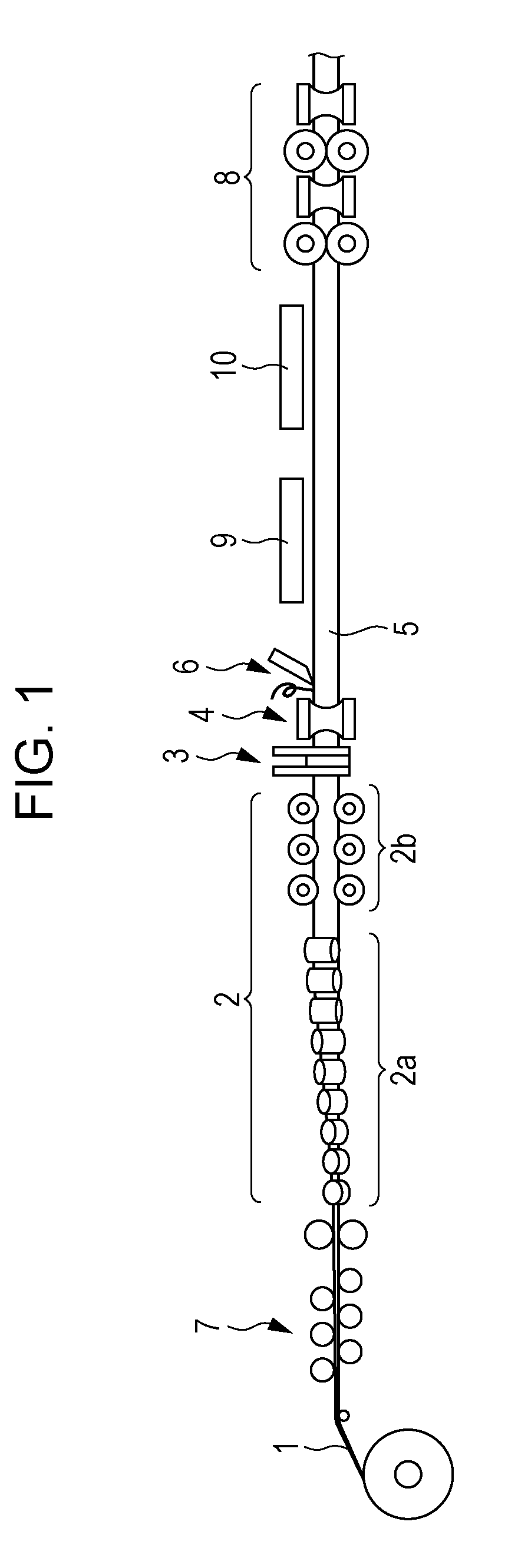
[0043] FIG. 1 is a schematic explanatory view of an example of a production line suitable for the manufacture of an electric-resistance-welded steel pipe according to the present disclosure.
[0044] FIG. 2 is a schematic explanatory view of an example of the shape of inner rolls.
[0045] FIG. 3 is a schematic explanatory view of an example of in-line heat treatment facilities.
DESCRIPTION OF EMBODIMENTS
[0046] A high-strength thick-walled electric-resistance-welded steel pipe according to the present disclosure is a high-strength thick-walled electric-resistance-welded steel pipe for a deep-well conductor casing. The term "high-strength thick-walled electric-resistance-welded steel pipe", as used herein, refers to a thick-walled electric-resistance-welded steel pipe having a thickness of 15 mm or more in which both a base material portion and an electric-resistance-welded portion have high strength of at least the API X80 grade. The base material portion has a yield strength YS of 555 MPa or more and a tensile strength TS of 625 MPa or more, and the electric-resistance-welded portion has a tensile strength TS of 625 MPa or more.
[0047] A high-strength thick-walled electric-resistance-welded steel pipe according to the present disclosure has a composition containing, on a mass percent basis, C: 0.01% to 0.12%, Si: 0.05% to 0.50%, Mn: 1.0% to 2.2%, P: 0.03% or less, S: 0.005% or less, Al: 0.001% to 0.10%, N: 0.006% or less, Nb: 0.010% to 0.100%, and Ti: 0.001% to 0.050%, optionally further containing one or two or more selected from V: 0.1% or less, Mo: 0.5% or less, Cr: 0.5% or less, Cu: 0.5% or less, Ni: 1.0% or less, and B: 0.0030% or less, and/or one or two selected from Ca: 0.0050% or less and REM: 0.0050% or less, the remainder being Fe and incidental impurities.
[0048] First, the reasons for limiting the composition of a high-strength thick-walled electric-resistance-welded steel pipe according to the present disclosure will be described below. Unless otherwise specified, the mass percentage of a component is simply expressed in %.
[0049] C: 0.01% to 0.12%
[0050] C is an important element that contributes to increased strength of a steel pipe. A C content of 0.01% or more is required to achieve desired high strength. However, a high C content of more than 0.12% results in poor weldability. Furthermore, during cooling after hot rolling or during in-line heat treatment of an electric-resistance-welded portion, a high C content of more than 0.12% makes the formation of martensite easier in the case of rapid cooling or the formation of a large amount of pearlite easier in the case of slow cooling, thereby possibly reducing toughness or strength. Thus, the C content is limited to the range of 0.01% to 0.12%. The lower limit of the C content is preferably 0.03% or more. The upper limit is preferably 0.10% or less, more preferably 0.08% or less.
[0051] Si: 0.05% to 0.50%
[0052] Si is an element that contributes to increased strength of a steel pipe by solid-solution strengthening. A Si content of 0.05% or more is required to achieve desired high strength by such an effect. Si has a higher affinity for O (oxygen) than Fe and, together with Mn oxide, forms a viscous eutectic oxide during electric resistance welding. Thus, an excessive Si content of more than 0.50% results in poor quality of an electric-resistance-welded portion. Thus, the Si content is limited to the range of 0.05% to 0.50%. The Si content preferably ranges from 0.05% to 0.30%.
[0053] Mn: 1.0% to 2.2%
[0054] Mn is an element that contributes to increased strength of a steel pipe. A Mn content of 1.0% or more is required to achieve desired high strength. However, in the same manner as in C, a high Mn content of more than 2.2% makes the formation of martensite easier and results in poor weldability. Thus, the Mn content is limited to the range of 1.0% to 2.2%. The lower limit of the Mn content is preferably 1.2% or more. The upper limit is preferably 2.0% or less.
[0055] P: 0.03% or Less
[0056] P exists as an impurity in steel, tends to segregate at grain boundaries, and adversely affects the steel pipe characteristics, such as toughness. Thus, the P content is preferably minimized. In the present disclosure, the allowable P content is up to 0.03%. Thus, the P content is limited to 0.03% or less. The P content is preferably 0.02% or less. However, an excessive reduction in P content increases refining costs. Thus, the P content is preferably 0.001% or more.
[0057] S: 0.005% or Less
[0058] S exists in the form of coarse sulfide inclusions, such as MnS, in steel and reduces ductility and toughness. Thus, the S content is desirably minimized. In the present disclosure, the allowable S content is up to 0.005%. Thus, the S content is limited to 0.005% or less. The S content is preferably 0.004% or less. However, an excessive reduction in S content increases refining costs. Thus, the S content is preferably 0.0001% or more.
[0059] Al: 0.001% to 0.10%
[0060] Al is an element that acts usefully as a deoxidizing agent for steel. Such an effect requires an Al content of 0.001% or more. However, a high Al content of more than 0.10% results in the formation of an Al oxide and low cleanliness of steel. Thus, the Al content is limited to the range of 0.001% to 0.10%. The lower limit of the Al content is preferably 0.005% or more. The upper limit is preferably 0.08% or less.
[0061] N: 0.006% or Less
[0062] N exists as an incidental impurity in steel and forms a solid solution or nitride, thereby reducing toughness of a base material portion or an electric-resistance-welded portion of a steel pipe. Thus, the N content is desirably minimized. In the present disclosure, the allowable N content is up to 0.006%. Thus, the N content is limited to 0.006% or less.
[0063] Nb: 0.010% to 0.100%
[0064] Nb is an important element in the present disclosure. While steel (a slab) is heated, Nb is present as Nb carbonitride in the steel, suppresses coarsening of austenite grains, and contributes to a finer structure. Nb forms fine precipitates during post-weld heat treatment performed at 600.degree. C. or more and contributes to a smaller decrease in the strength of a base material portion of a steel pipe after the post-weld heat treatment. Such an effect requires a Nb content of 0.010% or more. However, an excessive Nb content of more than 0.100% adversely affects the toughness of a steel pipe and possibly results in an inability to achieve the desired toughness of the steel pipe for a conductor casing. Thus, the Nb content is limited to the range of 0.010% to 0.100%. The lower limit of the Nb content is preferably 0.020% or more. The upper limit is preferably 0.080% or less.
[0065] Ti: 0.001% to 0.050%
[0066] Ti forms a Ti nitride combining with N and fixes N that adversely affects the toughness of a steel pipe, and thereby has the action of improving the toughness of the steel pipe. Such an effect requires a Ti content of 0.001% or more. However, a Ti content of more than 0.050% results in a significant decrease in the toughness of a steel pipe. Thus, the Ti content is limited to the range of 0.001% to 0.050%. The lower limit of the Ti content is preferably 0.005% or more. The upper limit is preferably 0.030% or less.
[0067] These components are base components. In addition to the base components, a steel pipe according to the present disclosure may contain one or two or more selected from V: 0.1% or less, Mo: 0.5% or less, Cr: 0.5% or less, Cu: 0.5% or less, Ni: 1.0% or less, and B: 0.0030% or less, and/or one or two selected from Ca: 0.0050% or less and REM: 0.0050% or less.
[0068] One or two or more selected from V: 0.1% or less, Mo: 0.5% or less, Cr: 0.5% or less, Cu: 0.5% or less, Ni: 1.0% or less, and B: 0.0030% or less
[0069] V, Mo, Cr, Cu, Ni, and B are elements that improve hardenability and contribute to increased strength of a steel plate, and can be appropriately selected for use. These elements reduce the formation of pearlite and polygonal ferrite particularly in thick plates having a thickness of 15 mm or more and are effective in achieving desired strength and toughness. It is desirable to contain V: 0.005% or more, Mo: 0.05% or more, Cr: 0.05% or more, Cu: 0.05% or more, Ni: 0.05% or more, and/or B: 0.0005% or more to produce such an effect. However, the content exceeding V: 0.1%, Mo: 0.5%, Cr: 0.5%, Cu: 0.5%, Ni: 1.0%, or B: 0.0030% may result in reduced weldability and toughness and increased material costs. Thus, the amounts of these elements are preferably limited to V: 0.1% or less, Mo: 0.5% or less, Cr: 0.5% or less, Cu: 0.5% or less, Ni: 1.0% or less, and B: 0.0030% or less, if any. V: 0.08% or less, Mo: 0.45% or less, Cr: 0.30% or less, Cu: 0.35% or less, Ni: 0.35% or less, and B: 0.0025% or less are more preferred.
[0070] One or two selected from Ca: 0.0050% or less and REM: 0.0050% or less
[0071] Ca and REM are elements that contribute to morphology control of inclusions in which elongated sulfide inclusions, such as MnS, are transformed into spherical sulfide inclusions, and can be appropriately selected for use. It is desirable to contain at least 0.0005% Ca or at least 0.0005% REM to produce such an effect. However, more than 0.0050% Ca or REM may result in increased oxide inclusions and reduced toughness. Thus, if present, Ca and REM are preferably limited to Ca: 0.0050% or less and REM: 0.0050% or less, respectively.
[0072] The remainder other than the components described above is made up of Fe and incidental impurities.
[0073] A high-strength thick-walled electric-resistance-welded steel pipe according to the present disclosure has the composition described above and has the structure in which a base material portion and an electric-resistance-welded portion of the high-strength thick-walled electric-resistance-welded steel pipe have a structure composed of 90% or more by volume of a bainitic ferrite phase as a main phase and 10% or less (including 0%) by volume of a second phase, the bainitic ferrite phase described above having an average grain size of 10 .mu.m or less, fine Nb precipitates having a particle size of less than 20 nm being dispersed in the base material portion, the ratio (%) of the fine Nb precipitates to the total amount of Nb being 75% or less on a Nb equivalent basis, and the circularity of an end portion of the steel pipe is 0.6% or less.
[0074] Main Phase: 90% or More by Volume of a Bainitic Ferrite Phase
[0075] In order to achieve desired high strength and high toughness for a conductor casing, both a base material portion and an electric-resistance-welded portion of an electric-resistance-welded steel pipe according to the present disclosure have a structure composed mainly of 90% or more by volume of a bainitic ferrite phase. Less than 90% of a bainitic ferrite phase or 10% or more of a second phase other than the main phase results in an inability to achieve desired toughness. The second phase other than the main phase may be a hard phase, such as pearlite, degenerate pearlite, bainite, or martensite. Thus, the volume percentage of the bainitic ferrite phase serving as the main phase is limited to 90% or more. The volume percentage of the bainitic ferrite phase is preferably 95% or more.
[0076] Average Grain Size of Bainitic Ferrite Phase: 10 .mu.m or Less
[0077] In order to achieve desired high strength and high toughness for a conductor casing, in the present disclosure, a bainitic ferrite phase serving as the main phase has a fine structure having an average grain size of 10 .mu.m or less. An average grain size of more than 10 .mu.m results in an inability to achieve desired high toughness. Thus, the average grain size of the bainitic ferrite phase serving as the main phase is limited to 10 .mu.m or less.
[0078] Fine Nb precipitates having a particle size of less than 20 nm: the ratio (%) of the Nb precipitates to the total amount of Nb is 75% or less on a Nb equivalent basis
[0079] Fine Nb precipitates (mainly carbonitride) having a particle size of less than 20 nm effectively contribute to achieving desired high strength. Thus, the ratio (%) of the fine Nb precipitates to the total amount of Nb is preferably 20% or more on a Nb equivalent basis. However, precipitation of more than 75% of the total amount of Nb on a Nb equivalent basis results in Ostwald growth of precipitates during post-weld heat treatment performed at a temperature of 600.degree. C. or more and reduces yield strength after post-weld heat treatment. Thus, in the present disclosure, the ratio (%) of fine Nb precipitates having a particle size of less than 20 nm in a base material portion of a steel pipe to the total amount of Nb is 75% or less on a Nb equivalent basis. Thus, fine Nb precipitates remain even after post-weld heat treatment and can suppress the decrease in yield strength. Thus, the ratio (%) of the amount of fine Nb precipitates having a particle size of less than 20 nm to the total amount of Nb on a Nb equivalent basis is limited to 75% or less.
[0080] The phrase "the amount of fine Nb precipitates having a particle size of less than 20 nm", as used herein, refers to a value determined by electrolyzing an electroextraction test piece taken from a base material portion of an electric-resistance-welded steel pipe in an electrolyte solution (10% by volume acetylacetone-1% by mass tetramethylammonium chloride-methanol solution), filtering the resulting electrolytic residue through a filter having a pore size of 0.02 .mu.m, and analyzing the amount of Nb passing through the filter.
[0081] A high-strength thick-walled electric-resistance-welded steel pipe according to the disclosed exemplary embodiments has the composition and structure described above, and the circularity of an end portion of the steel pipe is 0.6% or less.
[0082] Circularity: 0.6% or Less
[0083] If the circularity of an end portion of an electric-resistance-welded steel pipe is 0.6% or less, without cutting and/or straightening before the end portion of the pipe is joined to a connector by girth welding, linear misalignment in the joint is allowable, and the occurrence of breakage by repeated bending deformation can be reduced. If the circularity of an electric-resistance-welded steel pipe is more than 0.6%, the linear misalignment of a joint between the steel pipe and a connector (screw member) increases, and the joint is likely to be broken by the weight of the pipe and bending deformation during placement. Thus, the circularity of an electric-resistance-welded steel pipe is limited to 0.6% or less. The circularity of a steel pipe is defined by the following formula (1).
Circularity (%)={(maximum outer diameter mm.phi. of steel pipe)-(minimum outer diameter mm+ of steel pipe)}/(nominal outer diameter mm.phi.).times.100 (1)
[0084] It is desirable to continuously measure the maximum outer diameter and minimum outer diameter of a steel pipe with a laser displacement meter. In the case of manual measurement from necessity, the maximum outer diameter and minimum outer diameter of a steel pipe should be determined from measurements of at least 32 points on the circumference of the steel pipe.
[0085] In a deep-well conductor casing including a high-strength thick-walled electric-resistance-welded steel pipe according to the present disclosure, the high-strength thick-walled electric-resistance-welded steel pipe is provided with a screw member at each end thereof. The screw member may be attached by any method, for example, by MIG welding or TIG welding. The screw member may be made of, for example, carbon steel or stainless steel.
[0086] A method for manufacturing a high-strength thick-walled electric-resistance-welded steel pipe according to the present disclosure will be described below.
[0087] An electric-resistance-welded steel pipe according to the present disclosure is manufactured using a hot-rolled steel plate as a material.
[0088] More specifically, an electric-resistance-welded steel pipe according to the present disclosure is manufactured by continuously cold-rolling a hot-rolled steel plate with a roll forming machine (preferably with a cage roll group composed of a plurality of rolls and a fin pass forming roll group composed of a plurality of rolls) to form an open pipe having a generally circular cross section, butting against edges of the open pipe each other, electric-resistance-welding a portion where the edges butted while pressing the butted edges to contact each other by squeeze rolls to form an electric-resistance-welded steel pipe, subjecting the electric-resistance-welded portion of the electric-resistance-welded steel pipe to in-line heat treatment, and reducing the diameter of the electric-resistance-welded steel pipe by rolling.
[0089] The hot-rolled steel plate used as a material is a thick-hot-rolled steel plate having a thickness of 15 mm or more and preferably 51 mm or less manufactured by subjecting a steel having the composition described above to the following process.
[0090] The steel may be manufactured by any method. Preferably, a molten steel having the composition described above is produced by a conventional melting method, such as with a converter, and is formed into a cast block (steel), such as a slab, by a conventional casting process, such as a continuous casting process. Instead of the continuous casting process, a steel (steel block) may be manufactured by an ingot casting and slabbing process without problems.
[0091] A steel having the above composition is heated to a temperature in the range of 1150.degree. C. to 1250.degree. C. and is subjected to hot-rolling, which includes rough rolling and finish rolling, at a finishing delivery temperature of 750.degree. C. or more.
[0092] Heating Temperature: 1150.degree. C. to 1250.degree. C.
[0093] Although a low heating temperature at which finer crystal grains are expected to grow is preferred in order to improve the toughness of a hot-rolled steel plate, a heating temperature of less than 1150.degree. C. is too low to promote solid solution of undissolved carbide, failing to achieve the desired high strength of at least the API X80 grade in some cases. On the other hand, a high heating temperature of more than 1250.degree. C. may cause coarsening of austenite (y) grains, reduced toughness, more scales and poor surface quality, and result in economic disadvantages due to increased energy loss. Thus, the heating temperature of steel ranges from 1150.degree. C. to 1250.degree. C. The soaking time at the heating temperature is preferably 60 minutes or more, in order to make the temperature of steel which is heated uniform.
[0094] The rough rolling is not particularly limited, provided that the resulting sheet bar has a predetermined size and shape. The finishing delivery temperature of the finish rolling is adjusted to be 750.degree. C. or more. Here, the temperature is expressed in terms of a surface temperature.
[0095] Finishing Delivery Temperature: 750.degree. C. or More
[0096] A finishing delivery temperature of less than 750.degree. C. causes in induction of ferrite transformation, and processing of the resulting ferrite results in reduced toughness. Thus, the finishing delivery temperature is limited to 750.degree. C. or more. In the finish rolling, the rolling reduction in a non-recrystallization temperature range in which a temperature at the center of plate thickness is 950.degree. C. or less is preferably adjusted to be 20% or more. A rolling reduction of less than 20% in the non-recrystallization temperature range is an insufficient rolling reduction for the non-recrystallization temperature range and may therefore result in a small number of ferrite nucleation sites, thus failing to decrease the size of ferrite grains. Thus, the rolling reduction in the non-recrystallization temperature range is preferably adjusted to be 20% or more. From the viewpoint of the load to a rolling mill, the cumulative rolling reduction in hot rolling is preferably 95% or less.
[0097] In the present disclosure, after the completion of the hot rolling, cooling is immediately started preferably within 5 s (s refers to second). The hot-rolled plate is subjected to accelerated cooling such that the average cooling rate in a temperature range of 750.degree. C. to 650.degree. C. at the center of plate thickness ranges from 8.degree. C./s to 70.degree. C./s, and is coiled at a coiling temperature in the range of 400.degree. C. to 580.degree. C. The coiled plate is left to cool.
[0098] Average Cooling Rate of Accelerated Cooling in the Temperature Range of 750.degree. C. to 650.degree. C.: 8.degree. C./s to 70.degree. C./s
[0099] An average cooling rate of less than 8.degree. C./s in the temperature range of 750.degree. C. to 650.degree. C. is slow and results in a structure containing a coarse polygonal ferrite phase having an average grain size of more than 10 .mu.m and pearlite, thus failing to achieve the toughness and strength required for casing. On the other hand, an average cooling rate of more than 70.degree. C./s may result in the formation of a martensite phase and reduced toughness. Thus, the average cooling rate in the temperature range of 750.degree. C. to 650.degree. C. is limited to the range of 8.degree. C./s to 70.degree. C./s. The lower limit of the cooling rate is preferably 10.degree. C./s or more. The upper limit is preferably 50.degree. C./s or less. These temperatures are the temperatures at the center of plate thickness. The temperatures at the center of plate thickness are determined by calculating the temperature distribution in a cross section by heat transfer analysis and correcting the calculated data in accordance with the actual outer and inner surface temperatures.
[0100] The cooling stop temperature of the accelerated cooling preferably ranges from 400.degree. C. to 630.degree. C. in terms of the surface temperature. When the cooling stop temperature of the accelerated cooling is outside the temperature range of 400.degree. C. to 630.degree. C., the desired coiling temperature in the range of 400.degree. C. to 580.degree. C. may be impossible to consistently achieve.
[0101] Coiling Temperature: 400.degree. C. to 580.degree. C.
[0102] A high coiling temperature of more than 580.degree. C. causes promotion of precipitation of Nb carbonitride (precipitates), a Nb precipitation ratio of more than 75% after the coiling process, and results In reduced yield strength after post-weld heat treatment performed at a heating temperature of 600.degree. C. or more. On the other hand, a coiling temperature of less than 400.degree. C. causes insufficient precipitation of fine Nb carbonitride (precipitates) and results in an inability to achieve desired high strength (at least the API X80 grade). Thus, the coiling temperature is limited to a temperature in the range of 400.degree. C. to 580.degree. C. The coiling temperature preferably ranges from 460.degree. C. to 550.degree. C. When the coiling temperature is adjusted to be in this temperature range, the structure can contain fine Nb precipitates having a particle size of less than 20 nm dispersed in a base material portion, and the ratio (%) of the fine Nb precipitates to the total amount of Nb is 75% or less on a Nb equivalent basis. This can suppress the decrease in yield strength due to post-weld heat treatment performed at 600.degree. C. or more. These temperatures are expressed in terms of a plate surface temperature.
[0103] A hot-rolled steel plate manufactured under the conditions described above has a structure composed of 90% or more by volume of a bainitic ferrite phase as a main phase and 10% or less (including 0%) by volume of a second phase as the remainder other than the bainitic ferrite phase, the main phase having an average grain size of 10 .mu.m or less, fine Nb precipitates having a particle size of less than 20 nm being dispersed, the ratio (%) of the fine Nb precipitates to the total amount of Nb being 75% or less on a Nb equivalent basis. The hot-rolled steel plate has high strength of at least the API X80 grade, that is, a yield strength YS of 555 MPa or more, and high toughness represented by an absorbed energy vE.sub.-40 of 27 J or more in a Charpy impact test at a test temperature of -40.degree. C.
[0104] A hot-rolled steel plate (hot-rolled steel strip) 1 having the composition and structure described above is used as a steel pipe material and is continuously rolled with a roll forming machine 2 illustrated in FIG. 1 to form an open pipe having a generally circular cross section. After that, the edges of the open pipe are butted against each other while butted edges of the open pipe are pressed to contact each other by squeeze rolls 4, the portion where the edges being butted are heated to at least the melting point thereof and are electric-resistance-welded with a welding machine 3 by high-frequency resistance heating, high-frequency induction heating, or the like, thus forming an electric-resistance-welded steel pipe 5. The roll forming machine 2 preferably includes a cage roll group 2a composed of a plurality of rolls and a fin pass forming roll group 2b composed of a plurality of rolls.
[0105] The circularity is preferably improved by pressing two or more portions of an inner wall of a hot-rolled steel plate with at least one set of inner rolls 2a1 disposed downstream of the cage roll group 2a during a forming process. Preferably, the inner rolls disposed have shape as illustrated in FIG. 2 so as to press two or more positions from the viewpoint of improving circularity and reducing the load to facilities. FIG. 2 illustrates two sets of inner rolls 2a1 ((2a1).sub.1 and (2a1).sub.2).
[0106] Methods of roll forming, pressing by squeeze rolls, and electric resistance welding are not particularly limited, provided that an electric-resistance-welded steel pipe having predetermined dimensions can be manufactured, and any conventional method may be employed.
[0107] The electric-resistance-welded steel pipe thus formed is subjected to in-line heat treatment (seam annealing) of an electric-resistance-welded portion, as illustrated in FIG. 1.
[0108] In-line heat treatment of an electric-resistance-welded portion is preferably performed with an induction heating apparatus 9 and a cooling apparatus 10 disposed downstream of the squeeze rolls 4 such that the electric-resistance-welded portion can be heated, for example, as illustrated in FIG. 1. As illustrated in FIG. 3, the induction heating apparatus 9 preferably includes one or a plurality of coils 9a so as to enable one or a plurality of heating steps. By using a plurality of coils 9a, uniform heating can be achieved.
[0109] In the heat treatment of an electric-resistance-welded portion, preferably, the electric-resistance-welded portion is heated so as to the minimum temperature in the thickness direction being 830.degree. C. or more and the maximum heating temperature in the thickness direction being 1150.degree. C. or less and is cooled with water to a cooling stop temperature (at the center of plate thickness) of 550.degree. C. or less such that the average cooling rate in the temperature range of 800.degree. C. to 550.degree. C. at the center of plate thickness ranges from 10.degree. C./s to 70.degree. C./s. The cooling stop temperature may be lowered. When the minimum heating temperature in an electric-resistance-welded portion is less than 830.degree. C., the heating temperature may be too low to provide the desired structure of the electric-resistance-welded portion. On the other hand, a maximum heating temperature of more than 1150.degree. C. may result in coarsening of crystal grains and reduced toughness. Thus, the heating temperature of an electric-resistance-welded portion in heat treatment preferably ranges from 830.degree. C. to 1150.degree. C.
[0110] When the average cooling rate is less than 10.degree. C./s, this may promote the formation of polygonal ferrite and result in an inability to provide the desired structure of an electric-resistance-welded portion. On the other hand, rapid cooling with an average cooling rate of more than 70.degree. C./s may result in the formation of a hard phase, such as martensite, an inability to provide the desired structure of an electric-resistance-welded portion, and reduced toughness. Thus, the average cooling rate of cooling after heating preferably ranges from 10.degree. C./s to 70.degree. C./s. The cooling stop temperature is preferably 550.degree. C. or less. A high cooling stop temperature of more than 550.degree. C. may cause incomplete ferrite transformation, and formation of a coarse pearlite structure when left standing after cooling, and reduced in reduced toughness, or reduced strength.
[0111] The heat treatment (seam annealing) of an electric-resistance-welded portion can change the structure of the electric-resistance-welded portion into a structure similar to the structure of the base material portion, that is, a structure composed of 90% or more by volume of a bainitic ferrite phase as a main phase and 10% or less (including 0%) by volume of a second phase, the bainitic ferrite phase having an average grain size of 10 m or less.
[0112] Subsequently, the circularity is improved by reducing rolling.
[0113] The reducing rolling is preferably cold rolling with a sizer 8 composed of two or three or more pairs of rolls. In the reducing rolling, a reduction ratio in the range of 0.2% to 3.3% is preferable. A reduction ratio of less than 0.2% may result in an inability to achieve the desired circularity (0.6% or less). On the other hand, a reduction ratio of more than 3.3% may cause excessive circumferential compression and considerable thickness variations in the circumferential direction, and result in reduced efficiency of girth welding. Thus, in the reducing rolling, a reduction ratio in the range of 0.2% to 3.3% is preferable. The reduction ratio is calculated using the following formula.
Reduction ratio (%)={(outer perimeter of pipe before reducing rolling mm)-(outer perimeter of pipe after reducing rolling mm)}/(outer perimeter of pipe before reducing rolling mm).times.100
[0114] The circularity of an end portion of a high-strength thick-walled electric-resistance-welded steel pipe can be adjusted to be 0.6% or less by the reducing rolling.
[0115] Exemplary embodiments are described below in the following examples.
Examples
[0116] A molten steel having the composition listed in Table 1 (the remainder was made up of Fe and incidental impurities) was produced in a converter and was cast into a slab (a cast block having a thickness of 250 mm) by a continuous casting process. The slab was used as steel that is a starting material.
[0117] The steel obtained was reheated under the conditions (heating temperature (.degree. C.).times.holding time (min)) listed in Table 2 and was hot-rolled into a hot-rolled steel plate. The hot rolling included rough rolling and finish rolling. The hot-rolling was performed under the conditions of the rolling reduction (%) in a non-recrystallization temperature range and the finishing delivery temperature (.degree. C.) listed in Table 2. After the finish rolling, cooling was immediately started and here, accelerated cooling, that is, cooling was performed under the conditions of temperatures at the center of plate thickness (the average cooling rate in the temperature range of 750.degree. C. to 650.degree. C. and the cooling stop temperature) listed in Table 2 was performed. The resultant hot-rolled steel plate was coiled at a coiling temperature listed in Table 2 to produce a steel pipe material.
TABLE-US-00001 TABLE 1 Steel Chemical components (mass %) No. C Si Mn P S Al N Nb Ti V, Mo, Cr, Cu, Ni, B Ca, REM Remarks A 0.090 0.15 1.90 0.006 0.0050 0.034 0.003 0.037 0.010 -- -- Working example B 0.054 0.15 1.74 0.012 0.0009 0.026 0.0003 0.060 0.015 V: 0.08 -- Working example C 0.050 0.20 1.55 0.012 0.0005 0.032 0.004 0.060 0.015 Mo: 0.28, Cu: 0.22, -- Working example Ni: 0.20 D 0.066 0.23 1.82 0.010 0.0016 0.037 0.004 0.063 0.016 V: 0.04, Cr: 0.13 -- Working example E 0.022 0.23 1.45 0.015 0.0022 0.026 0.002 0.055 0.014 V: 0.07, Mo: 0.15, Ca: 0.0025 Working example Cu: 0.32 F 0.040 0.18 1.60 0.010 0.0010 0.033 0.002 0.025 0.045 Mo: 0.10, Ni: 0.25 Ca: 0.0020 Working example G 0.032 0.28 2.06 0.010 0.0019 0.040 0.003 0.053 0.012 Mo: 0.37, Cr: 0.40, REM: 0.003 Working example B: 0.0022 H 0.004 0.22 1.85 0.010 0.0010 0.030 0.003 0.032 0.020 V: 0.075, Cu: 0.22, -- Comparative example Ni: 0.24 I 0.146 0.20 1.44 0.012 0.0025 0.023 0.004 0.024 0.008 V: 0.043 Ca: 0.0011 Comparative example J 0.042 0.56 1.58 0.005 0.0015 0.038 0.004 0.052 0.016 Cr: 0.23, Ni: 0.15 Ca: 0.0022 Comparative example K 0.037 0.19 0.65 0.017 0.0008 0.021 0.003 0.080 0.017 -- -- Comparative example L 0.036 0.35 2.31 0.012 0.0008 0.048 0.003 0.025 0.012 Cu: 0.15, Ni: 0.13 Ca: 0.0025 Comparative example M 0.050 0.27 1.36 0.006 0.0021 0.045 0.004 0.002 0.005 V: 0.040 -- Comparative example N 0.071 0.21 1.26 0.012 0.0006 0.031 0.003 0.131 0.015 Mo: 0.18, Cr: 0.32 -- Comparative example O 0.061 0.23 1.05 0.008 0.0007 0.041 0.001 0.015 0.065 -- -- Comparative example
TABLE-US-00002 TABLE 2 Hot rolling Cooling after Heating Rolling hot rolling Hot- Heating reduction in non- Finishing Average Coiling rolled temper- Holding recrystallization delivery cooling Cooling stop Coiling Plate plate Steel ature time temperature range* temperature** rate** temperature*** temperature** thickness No. No. (.degree. C.) (min) (%) (.degree. C.) (.degree. C./s) (.degree. C.) (.degree. C.) (mm) Remarks 1 A 1210 90 40 820 18 540 520 25.2 Working example 2 B 1210 75 40 810 20 540 530 20.4 Working example 3 C 1200 80 50 800 20 510 500 22.0 Working example 4 D 1220 90 20 820 16 560 540 25.2 Working example 5 E 1230 90 85 820 30 520 500 25.2 Working example 6 F 1180 65 55 780 22 520 500 20.4 Working example 7 G 1200 100 60 820 45 490 470 18.9 Working example 8 H 1200 100 20 820 25 480 460 18.9 Comparative example 9 I 1200 120 85 820 18 490 460 25.2 Comparative example 10 J 1190 75 40 780 28 500 480 15.7 Comparative example 11 K 1170 80 50 830 16 520 500 25.2 Comparative example 12 L 1200 80 20 820 20 560 540 22.0 Comparative example 13 M 1210 90 85 820 35 570 540 25.2 Comparative example 14 N 1210 90 40 820 20 515 500 20.4 Comparative example 15 O 1230 95 40 840 25 470 450 18.9 Comparative example 16 A 1100 100 50 820 18 440 420 25.2 Comparative example 17 A 1300 100 50 820 60 500 480 17.3 Comparative example 18 A 1230 105 20 820 5 540 520 22.0 Comparative example 19 A 1200 90 85 820 100 440 420 25.2 Comparative example 20 A 1200 95 40 780 18 680 650 25.2 Comparative example 21 A 1200 90 40 840 45 355 350 25.2 Comparative example 22 C 1280 100 50 820 25 520 500 18.9 Comparative example 23 C 1220 100 20 820 120 500 480 25.2 Comparative example 24 C 1210 110 85 820 20 730 700 20.4 Comparative example 25 E 1110 110 55 790 20 500 480 22.0 Comparative example 26 E 1180 100 60 820 3 520 500 25.2 Comparative example 27 E 1180 90 20 820 15 310 300 25.2 Comparative example 28 F 1100 90 20 800 15 515 500 25.2 Comparative example 29 F 1170 85 85 820 5 525 520 25.2 Comparative example 30 F 1190 75 40 820 25 650 630 18.9 Comparative example 31 G 1300 75 40 790 20 600 580 25.2 Comparative example 32 G 1200 80 50 820 110 565 550 15.7 Comparative example *Temperature range of 930.degree. C. or less **Surface temperature ***Temperature at the center of plate thickness
[0118] The hot-rolled steel plate serving as a steel pipe material was continuously cold-rolled with a roll forming machine including a cage roll group composed of a plurality of rolls and a fin pass forming roll group composed of a plurality of rolls, thereby forming an open pipe having a generally circular cross section. Then, the edges of the open pipe, which were opposite each other, were butted together. While butted edges of the open pipe were pressed to contact each other by squeeze rolls, the portion where the edges were butted was electric-resistance-welded to form an electric-resistance-welded steel pipe. In some electric-resistance-welded steel pipes, at least two portions, which were separate each other in the width direction, of the inner wall of the semi-formed product were pressed with inner rolls disposed downstream of the cage roll group.
[0119] The electric-resistance-welded portion of the electric-resistance-welded steel pipe was then subjected to in-line heat treatment under the conditions listed in Table 3. The in-line heat treatment was performed with an in-line heat treatment apparatus disposed downstream of the squeeze rolls. The in-line heat treatment apparatus included an induction heating apparatus and a water cooling apparatus. The average cooling rate and the cooling stop temperature were expressed in terms of a temperature at the center of plate thickness. The average cooling rate listed was an average cooling rate in the temperature range of 800.degree. C. to 550.degree. C.
[0120] The electric-resistance-welded steel pipe subjected to the in-line heat treatment was subjected to reducing-cold-rolling with a reducing rolling mill (sizer roll) at the reduction ratio listed in Table 3, thereby forming an electric-resistance-welded steel pipe having the dimensions listed in Table 3. The reducing rolling mill included 2 to 8 sets of rolls, as listed in Table 3. Some electric-resistance-welded steel pipes were not subjected to reducing rolling. The circularity of an end portion of a pipe was calculated using the formula (1). The outer diameters listed in Table 3 were nominal outer diameters.
TABLE-US-00003 TABLE 3 Heat treatment of electric- resistance-welded portion Dimensions of steel pipe Hot- Maximum Average Reducing rolling Circularity Steel rolled heating cooling Cooling stop Number of Outer of end pipe plate Steel temperature rate temperature rolls in Reduction Thickness diameter portion of No. No. No. (.degree. C.) (.degree. C./s) (.degree. C.) sizer mill ratio (%) (mm) (mm.phi.) pipe (%) Remarks 1 1 A 1120 15 450 2 0.4 25.4 558.8 0.45 Working example 2 2 B 1080 25 500 2 0.4 20.6 558.8 0.43 Working example 3* 3 C 1100 20 500 3 0.5 22.2 558.8 0.32 Working example 4* 4 D 1100 15 500 3 0.5 25.4 609.6 0.35 Working example 5 5 E 1090 15 480 4 0.4 25.4 558.8 0.27 Working example 6* 6 F 1060 20 400 4 0.4 20.6 558.8 0.26 Working example 7* 7 G 1050 25 450 8 0.3 19.1 660.4 0.15 Working example 8 8 H 1050 25 350 2 0.3 19.1 558.8 0.42 Comparative example 9 9 I 1080 15 350 2 0.5 25.4 558.8 0.45 Comparative example 10 10 J 1100 33 300 2 0.5 15.9 558.8 0.44 Comparative example 11 11 K 1120 15 480 4 0.5 25.4 558.8 0.33 Comparative example 12 12 L 1100 15 450 4 0.5 22.2 558.8 0.34 Comparative example 13 13 M 1020 15 500 4 0.5 25.4 558.8 0.29 Comparative example 14* 14 N 1000 20 300 4 0.5 20.6 558.8 0.28 Comparative example 15 15 O 1040 30 300 4 0.5 19.1 457.2 0.28 Comparative example 16* 16 A 1070 15 350 3 0.4 25.4 558.8 0.32 Comparative example 17 17 A 1075 30 400 2 0.4 17.5 609.6 0.42 Comparative example 18 18 A 1060 15 350 2 0.4 22.2 508.0 0.45 Comparative example 19 19 A 1050 15 350 2 0.4 25.4 609.6 0.42 Comparative example 20 20 A 1100 15 400 2 0.6 25.4 457.2 0.45 Comparative example 21 21 A 1100 15 300 2 0.6 25.4 558.8 0.44 Comparative example 22 22 C 1100 25 300 2 0.6 19.1 558.8 0.42 Comparative example 23 23 C 1120 15 350 2 0.6 25.4 558.8 0.40 Comparative example 24 24 C 1080 20 350 2 0.6 20.6 558.8 0.40 Comparative example 25 25 E 1070 20 400 2 0.6 22.2 508.0 0.44 Comparative example 26 26 E 1080 15 400 2 0.6 25.4 558.8 0.44 Comparative example 27 27 E 1060 15 380 2 0.5 25.4 558.8 0.44 Comparative example 28 28 F 1100 15 450 2 0.5 25.4 508.0 0.48 Comparative example 29 29 F 1100 20 440 2 0.5 25.4 558.8 0.38 Comparative example 30 30 F 1030 25 430 2 0.5 19.1 558.8 0.40 Comparative example 31 31 G 1100 20 470 2 0.5 25.4 558.8 0.41 Comparative example 32 32 G 990 55 450 2 0.4 15.9 558.8 0.40 Comparative example 33 17 A 1080 25 300 -- -- 17.5 406.4 0.86 Comparative example *With use of inner rolls
[0121] Test pieces were taken from the electric-resistance-welded steel pipe and were subjected to structure observation, a tensile test, an impact test, and a post-weld heat treatment test. These test methods are described below.
(1) Structure Observation
[0122] A test piece for structure observation was taken from a base material portion (a position at an angle of 90 degrees with respect to the electric-resistance-welded portion in the circumferential direction) and the electric-resistance-welded portion of the electric-resistance-welded steel pipe. The base material portion was polished and etched (etchant: nital) such that the observation surface was at a the central position of the plate thickness, that is, at a center of the thickness, in a cross section in the longitudinal direction of the pipe (L cross section). The electric-resistance-welded portion was polished and etched (etchant: nital) such that the observation surface was a cross section in the circumferential direction of the pipe (C cross section). The structure was observed with a scanning electron microscope (SEM) (magnification: 1000), and images were taken in at least 2 fields. The structure images were analyzed to identify the structure and to determine the fraction of each phase. The average of the area fractions thus determined was treated as the volume fraction.
[0123] Grain boundaries having an orientation difference of 15 degrees or more were determined by a SEM/electron back scattering diffraction (EBSD) method. The arithmetic mean of the equivalent circular diameters of the grains determine was defined to be the average grain size of the main phase. "Orientation Imaging Microscopy Data Analysis", which is a software available from AMETEK Co., Ltd., was used for the calculation of the grain size.
[0124] Specimen for an electroextraction test piece was taken from the base material portion of the electric-resistance-welded steel pipe (a position at an angle of 90 degrees with respect to the electric-resistance-welded portion in the circumferential direction) and was electrolyzed at a current density of 20 mA/cm.sup.2 in an electrolyte solution (10% by volume acetylacetone-1% by mass tetramethylammonium chloride-methanol solution). The resulting electrolytic residue was dissolved in a liquid and was collected with an aluminum filter (pore size: 0.02 .mu.m). The amount of Nb in the filtrate was measured by ICP spectroscopy and was considered to be the amount of precipitated Nb having a grain size of 20 nm or less. The ratio (%) of the amount of precipitated Nb to the total amount of Nb was calculated.
(2) Tensile Test
[0125] A plate-like tensile test piece was taken from the base material portion (a position at an angle of 180 degrees with respect to the electric-resistance-welded portion in the circumferential direction) and the electric-resistance-welded portion of the electric-resistance-welded steel pipe according to ASTM A 370 such that the tensile direction was a direction perpendicular to the longitudinal direction of the pipe (C direction). The tensile properties (yield strength YS and tensile strength TS) of the tensile test piece were measured.
(3) Impact Test
[0126] A V-notched test piece was taken from the base material portion (a position at an angle of 90 degrees with respect to the electric-resistance-welded portion in the circumferential direction) and the electric-resistance-welded portion of the electric-resistance-welded steel pipe according to ASTM A 370 such that the longitudinal direction of the test piece was the circumferential direction (C direction). The absorbed energy vE.sub.-40 (J) each of three test pieces for a steel pipe was measured in a Charpy impact test at a test temperature of -40.degree. C. The average value of the three measurements was considered to be the vE.sub.-40 of the steel pipe.
(4) Post-Weld Heat Treatment Test
[0127] A test material was taken from the base material portion of the electric-resistance-welded steel pipe. The test material was placed in a heat treatment furnace maintained at a heating temperature simulating post-weld heat treatment listed in Table 5. When a predetermined holding time listed in Table 5 elapsed since the temperature of the test material reached (heating temperature--10.degree. C.), the test material was removed from the heat treatment furnace and was left to cool. A plate-like tensile test piece was taken from the heat-treated test material according to ASTM A 370 such that the tensile direction was a direction perpendicular to the longitudinal direction of the pipe (C direction). The tensile properties (yield strength YS and tensile strength TS) of the tensile test piece were measured. A difference .DELTA.YS in yield strength between before and after the post-weld heat treatment was calculated. If the strength is decreased after the post-weld heat treatment, the .DELTA.YS is negative. For reference, an electroextraction test piece was taken from the test material after the post-weld heat treatment, and the ratio of the amount of precipitated Nb was determined in the same manner as in (1).
[0128] Tables 4 and 5 show the results.
TABLE-US-00004 TABLE 4 Base material portion Electric-resistance-welded portion Hot- Structure Strength Toughness Structure Strength Toughness Steel rolled Fraction of main Average grain Precipitated Yield Tensile Absorbed Fraction of main Average grain Tensile Absorbed pipe plate Steel phase structure size of main Nb ratio** strength strength energy phase structure size of main strength energy No. No. No. Type* (vol %) phase (.mu.m) (%) YS (MPa) TS (MPa) vE-40(J) Type* (vol %) phase (.mu.m) TS (MPa) vE-40(J) Remarks 1 1 A BF + B BF: 98 4.5 62 582 664 234 BF 100 5.6 650 196 Working example 2 2 B BF BF: 100 5.1 57 624 701 311 BF 100 5.3 660 225 Working example 3 3 C BF BF: 100 6.6 48 574 650 341 BF 100 6.2 654 189 Working example 4 4 D BF + B BF: 96 4.3 67 610 692 300 BF 100 6.3 680 199 Working example 5 5 E BF BF: 100 4.9 45 596 676 340 BF 100 6.6 672 194 Working example 6 6 F BF BF: 100 4.1 48 580 674 336 BF 100 6.8 666 223 Working example 7 7 G BF BF: 100 4.2 45 722 849 215 BF 100 7.1 801 237 Working example 8 8 H BF BF: 100 4.0 38 412 460 452 BF 100 7.0 650 169 Comparative example 9 9 I F + BF + P F: 92 5.5 41 486 609 20 B 100 7.5 630 88 Comparative example 10 10 J BF + F BF: 97 5.9 49 563 634 282 BF 100 5.4 651 16 Comparative example 11 11 K BF + F BF: 85 8.3 54 529 608 360 BF 100 5.1 580 255 Comparative example 12 12 L B + M B: 90 3.7 71 576 677 10 B 100 6.0 640 25 Comparative example 13 13 M BF BF: 100 7.2 -- 492 562 386 BF 100 6.1 627 221 Comparative example 14 14 N BF BF: 100 4.3 53 605 685 11 BF 100 6.4 675 173 Comparative example 15 15 O BF + F BF: 95 5.5 32 612 699 8 BF 100 6.6 633 162 Comparative example 16 16 A BF + B BF: 96 4.4 15 541 637 356 BF 100 6.9 644 190 Comparative example 17 17 A BF + B BF: 86 11.5 68 585 678 20 BF 100 6.8 643 189 Comparative example 18 18 A F + P F: 92 12.8 66 499 640 14 BF 100 5.7 667 217 Comparative example 19 19 A M + B M: 55 2.7 38 524 760 17 BF 100 5.4 651 215 Comparative example 20 20 A BF + F + P BF: 80 8.6 85 624 711 22 BF 100 6.3 646 231 Comparative example 21 21 A BF + B BF: 89 4.4 18 533 605 410 BF 100 6.4 659 166 Comparative example 22 22 C BF + B BF: 88 7.8 55 642 682 9 BF 100 5.7 640 190 Comparative example 23 23 C M + B M: 60 3.3 53 559 780 19 BF 100 5.4 642 192 Comparative example 24 24 C BF + F + P BF: 95 8.5 95 571 680 30 BF 100 5.7 639 225 Comparative example 25 25 E BF BF: 100 3.5 13 489 555 415 BF 100 5.4 671 202 Comparative example 26 26 E F + B F: 94 10.5 65 470 553 287 BF 100 6.3 675 145 Comparative example 27 27 E BF + B BF: 94 3.8 18 522 639 311 BF 100 6.4 664 166 Comparative example 28 28 F BF BF: 100 4.5 12 538 674 382 BF 100 6.7 653 178 Comparative example 29 29 F F + P F: 93 11.2 73 460 541 366 BF 100 6.9 658 227 Comparative example 30 30 F BF + P BF: 96 7.7 88 593 706 333 BF 100 7.2 668 210 Comparative example 31 31 G BF BF: 100 10.2 70 660 880 16 B 100 7.1 810 194 Comparative example 32 32 G B + M B: 70 4.5 68 734 895 22 B 100 7.6 812 197 Comparative example 33 17 A BF + B BF: 95 11.1 65 580 675 19 BF 100 6.7 650 176 Comparative example *BF: bainitic ferrite, B: bainite, P: pearlite, M: martensite, F: ferrite **Amount of precipitated Nb: Amount of precipitated Nb having a particle size less than 20 nm (Ratio (%) relative to the total amount of Nb on a Nb equivalent basis)
TABLE-US-00005 TABLE 5 Difference in Post-weld heat Strength after post- strength between Hot- treatment conditions weld heat treatment before and after post- Steel rolled Heating Yield Tensile weld heat treatment Precipitated pipe plate Steel temperature Holding strength strength .DELTA.YS Nb ratio* No. No. No. (.degree. C.) time (h) YS (MPa) TS (MPa) (MPa) (%) Remarks 1 1 A 620 2 622 666 40 95 Working example 2 2 B 620 2 670 695 46 90 Working example 3 3 C 670 1 622 643 48 88 Working example 4 4 D 670 1 650 684 40 89 Working example 5 5 E 650 2 634 662 38 85 Working example 6 6 F 650 2 640 660 60 92 Working example 7 7 G 650 4 766 839 44 92 Working example 8 8 H 620 2 435 455 23 91 Comparative example 9 9 I 620 2 530 579 44 95 Comparative example 10 10 J 650 1 606 627 43 96 Comparative example 11 11 K 675 2 570 603 41 96 Comparative example 12 12 L 620 2 618 662 42 94 Comparative example 13 13 M 650 2 493 521 1 -- Comparative example 14 14 N 675 2 627 681 22 94 Comparative example 15 15 O 620 2 633 690 21 90 Comparative example 16 16 A 620 2 511 588 -30 10 Comparative example 17 17 A 620 2 623 663 38 92 Comparative example 18 18 A 650 2 538 625 39 90 Comparative example 19 19 A 620 2 568 745 44 92 Comparative example 20 20 A 675 2 604 696 -20 50 Comparative example 21 21 A 650 2 575 653 42 56 Comparative example 22 22 C 620 2 672 685 30 90 Comparative example 23 23 C 675 2 593 765 34 90 Comparative example 24 24 C 620 2 554 622 -17 63 Comparative example 25 25 E 620 2 495 540 6 17 Comparative example 26 26 E 675 2 503 538 33 90 Comparative example 27 27 E 650 2 560 624 38 68 Comparative example 28 28 F 620 2 540 659 2 20 Comparative example 29 29 F 650 2 500 526 40 89 Comparative example 30 30 F 675 2 550 691 -43 60 Comparative example 31 31 G 620 2 694 865 34 92 Comparative example 32 32 G 650 2 769 880 35 90 Comparative example 33 17 A 650 2 615 658 35 90 Comparative example *Amount of precipitated Nb after post-weld heat treatment (Ratio (%) relative to the total amount of Nb on a Nb equivalent basis)
[0129] All the working examples of the present disclosure are electric-resistance-welded steel pipes that are suitable for a deep-well conductor casing, have high strength of the API X80 grade, that is, a yield strength YS of 555 MPa or more and a tensile strength TS of 625 MPa or more, have good low-temperature toughness, suffer a smaller decrease in strength even after post-weld heat treatment, and have high resistance to post-weld heat treatment. The comparative examples outside the scope of the present disclosure are insufficient in strength, low-temperature toughness, or resistance to post-weld heat treatment.
REFERENCE SIGNS LIST
[0130] 1 Hot-rolled steel plate (hot-rolled steel strip) [0131] 2 Roll forming machine [0132] 3 Welding machine [0133] 4 Squeeze roll [0134] 5 Electric-resistance-welded steel pipe [0135] 6 Bead cutter [0136] 7 Leveler [0137] 8 Sizer [0138] 9 Inline heat treatment apparatus (induction heating apparatus) [0139] 10 Cooling apparatus [0140] 11 Thermometer
* * * * *
D00000
D00001
D00002
XML
uspto.report is an independent third-party trademark research tool that is not affiliated, endorsed, or sponsored by the United States Patent and Trademark Office (USPTO) or any other governmental organization. The information provided by uspto.report is based on publicly available data at the time of writing and is intended for informational purposes only.
While we strive to provide accurate and up-to-date information, we do not guarantee the accuracy, completeness, reliability, or suitability of the information displayed on this site. The use of this site is at your own risk. Any reliance you place on such information is therefore strictly at your own risk.
All official trademark data, including owner information, should be verified by visiting the official USPTO website at www.uspto.gov. This site is not intended to replace professional legal advice and should not be used as a substitute for consulting with a legal professional who is knowledgeable about trademark law.